Endereço
304 North Cardinal
St. Dorchester Center, MA 02124
Horas de trabalho
De segunda a sexta-feira: das 7h às 19h
Fim de semana: 10:00 - 17:00
Endereço
304 North Cardinal
St. Dorchester Center, MA 02124
Horas de trabalho
De segunda a sexta-feira: das 7h às 19h
Fim de semana: 10:00 - 17:00

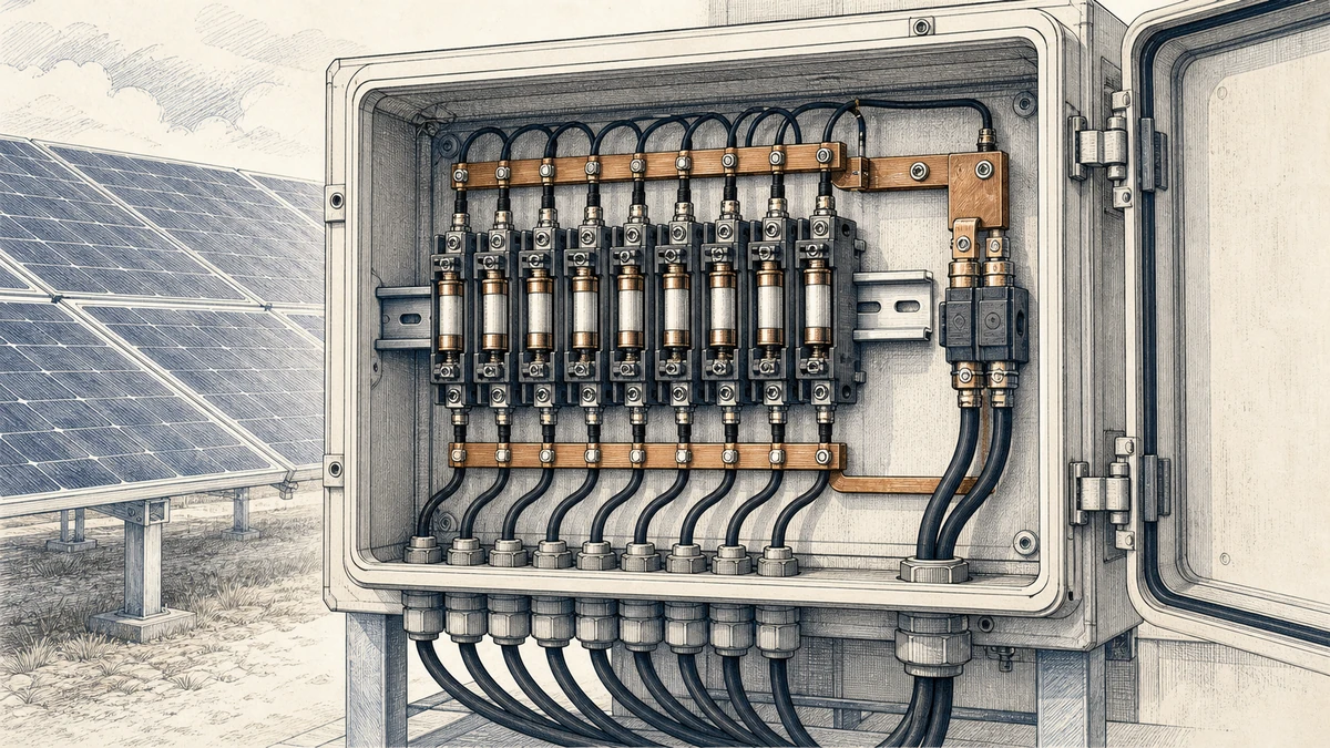
In photovoltaic DC circuits, fuse selection is rarely a simple nameplate-current exercise. A PV string or array can operate at high DC voltage while delivering limited fault current, which means the protective device must interrupt low overcurrents reliably without opening during normal irradiance changes, temperature swings, or inverter operating cycles.
For Sinobreaker DC Fuse applications, the gPV fuse time current curve is one of the most important tools for balancing two goals: clearing real PV faults and avoiding nuisance operation. The curve helps designers estimate how quickly a fuse will melt or clear at different current levels, but it must always be used with the exact fuse family, voltage rating, installation conditions, and system verification in mind.
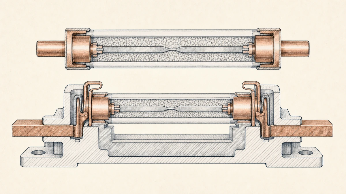
IEC 60269-6 defines supplementary requirements for fuse-links used to protect photovoltaic strings and arrays in circuits up to 1,500 V DC. This matters because PV faults are different from many AC distribution faults.
A conventional fuse may be designed around higher available fault current. In a PV array, fault current can be only modestly above operating current, especially under certain irradiance, temperature, and array-configuration conditions. A gPV fuse is designed for photovoltaic duty, including the ability to interrupt low overcurrents at full DC voltage when applied within its ratings.
A gPV fuse is typically used to protect PV strings, sub-arrays, combiner box outputs, and related DC circuits where reverse current or array backfeed could damage cables or modules. It is not selected only to match the normal string current; it must coordinate with the full PV circuit design.
Key protection targets include:
PV systems may have high open-circuit voltage but limited short-circuit current. Unlike some power systems where a short circuit produces a very high fault level, PV current is constrained by module characteristics and irradiance.
That creates a narrow selection window. If the fuse rating is too low, normal operating current, hot ambient conditions, or daily cycling can cause nuisance operation. If the fuse rating is too high, the fuse may not respond quickly enough to damaging reverse currents or persistent low-level faults.
A time-current curve plots current magnitude against operating time. For fuses, the curve typically shows how long the fuse takes to melt or clear at a given current. The higher the current, the faster the fuse operates.
In practice, the curve is a design aid. It helps compare expected operating current, overload current, and fault current against fuse behavior. However, it does not replace application testing, manufacturer data, or engineering verification.
When reading a gPV fuse time current curve, it is important to understand whether the curve shows melting time, clearing time, or both.
Melting time is the time required for the fuse element to melt. Clearing time includes melting time plus the arcing time required to fully interrupt the current. In DC PV systems, clearing behavior is especially important because DC arcs do not naturally pass through zero as AC arcs do.
For protection decisions, clearing time is usually the more complete value because it represents the time until the fault current is actually interrupted.
A fuse curve should be read in relation to current multiple, not only amperes. For example, a 15 A fuse and a 30 A fuse may both experience 45 A, but that current is three times rating for the 15 A fuse and only 1.5 times rating for the 30 A fuse. Their operating times will be very different.
This is why designers should avoid treating one curve as universal. Manufacturer photovoltaic-fuse data publishes time-current curves alongside device-specific ratings, dimensions, voltage duty, and breaking capacity. The curve must match the exact product family and application rating.
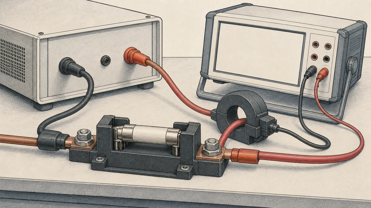
A curve becomes useful only when it is compared with real circuit values. For a Sinobreaker DC Fuse selection, start with the PV module data, string configuration, maximum system voltage, conductor ampacity, expected operating current, and available fault current.
The fuse must be rated for the maximum DC voltage of the PV circuit. For modern PV arrays, this may be up to 1,000 V DC or 1,500 V DC depending on the system architecture.
Never select a fuse by current rating alone. A fuse that appears suitable by amperage but lacks the correct DC voltage rating may fail to interrupt safely. The time-current curve is meaningful only when the device is applied within its rated voltage duty.
Determine the expected maximum operating current of the PV string or branch. This usually starts from the module short-circuit current and applicable design multipliers required by local codes, project specifications, and environmental assumptions.
The selected fuse should not operate during normal maximum production. The curve should show that expected operating current remains well below the fuse’s long-duration operating region, with appropriate allowance for ambient temperature, enclosure heating, and daily thermal cycling.
Next, calculate the available reverse current or fault current that the fuse may need to interrupt. In PV combiner applications, this often depends on the number of parallel strings and the maximum current that healthy strings can feed into a faulted string.
The selected gPV fuse must operate at damaging fault-current levels quickly enough to protect cables and modules. Because PV fault current can be relatively low, the curve should be checked carefully in the low-overcurrent region rather than only at high multiples of rated current.
Fuse operation must coordinate with the protected equipment. The cable, connector, module, and combiner components must tolerate the current for the time shown on the curve.
If the curve indicates that a low-level fault could persist too long, the fuse rating or system design may need adjustment. If the curve indicates operation during expected normal current, nuisance operation risk is too high.
Nuisance operation occurs when a fuse opens without a damaging fault. In PV systems, this can result in lost generation, difficult troubleshooting, unnecessary service visits, and reduced confidence in the protection design.
PV combiner boxes are often installed outdoors, exposed to high ambient temperatures and solar loading. Inside the enclosure, heat from terminals, busbars, adjacent devices, and limited airflow can further raise fuse temperature.
A fuse operating in a hot enclosure may run closer to its thermal limit than expected. When reading the curve, designers should apply manufacturer derating guidance and account for actual mounting conditions.
PV current rises and falls every day. Clouds, inverter MPPT behavior, and seasonal irradiance changes create repeated thermal cycling in the fuse element. Over time, this can influence performance if the fuse is selected too close to continuous operating current.
A conservative margin between normal current and the curve’s long-time operating region helps reduce unwanted fuse aging and nuisance operation.
Fuseholders, disconnects, combiner boxes, and enclosure layouts affect heat dissipation. Closely spaced components or poor ventilation can raise operating temperature. Altitude can also affect cooling and insulation performance.
For reliable Sinobreaker DC Fuse application, installation conditions should be treated as part of the protection design, not as afterthoughts.
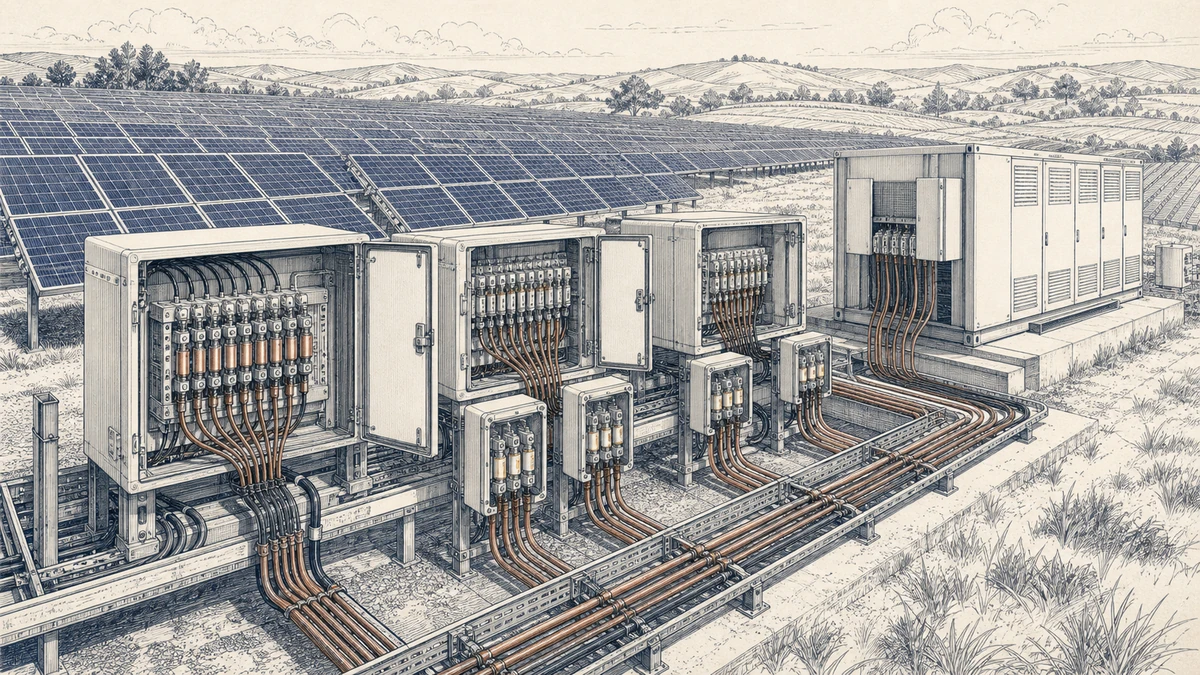
A practical design review should test the selected fuse against several operating points.
Plot the expected maximum continuous current on the curve. This point should fall in a region where the fuse does not operate during normal service, including hot ambient conditions and reasonable design tolerances.
If the point is close to the melting region, nuisance operation is likely.
Plot the lowest fault current that must be cleared. This is often the most important point in PV applications because available fault current may be limited.
If the curve shows a very long clearing time at this current, verify whether the protected cable and PV equipment can withstand the condition. If not, consider a different rating, revised string grouping, or another protection strategy.
Confirm that the fuse has adequate interrupting capacity for the maximum available fault current at the system voltage. The curve helps estimate operation time, but breaking capacity and DC voltage rating confirm whether the device can safely interrupt.
PV systems may include string fuses, array fuses, DC disconnects, surge protection, inverter inputs, and monitoring devices. Fuse coordination should help isolate the faulted section without unnecessarily disconnecting larger portions of the system.
The curve can support coordination, but device-specific data and system testing remain necessary.
A gPV fuse time current curve belongs to a specific product family, construction, rating, and voltage duty. Curves from another manufacturer, size, or voltage class should not be used as substitutes.
Even if two fuses have the same current rating, their melting and clearing behavior may differ.
Choosing a fuse only because its rated current is slightly above operating current can lead to problems. The design must also consider PV module limits, conductor ampacity, reverse-current risk, available fault current, voltage rating, temperature, and mounting.
PV faults may not produce dramatic current levels. A fuse that performs well at high multiples of rated current may still be unsuitable if it clears too slowly at low overcurrent levels relevant to the array.
Time-current curves are valuable, but they are not a complete substitute for application testing. Final selection should be verified against the actual system design, local code requirements, manufacturer instructions, and project operating conditions.
Use the following checklist when applying a Sinobreaker DC Fuse in PV string or array protection:
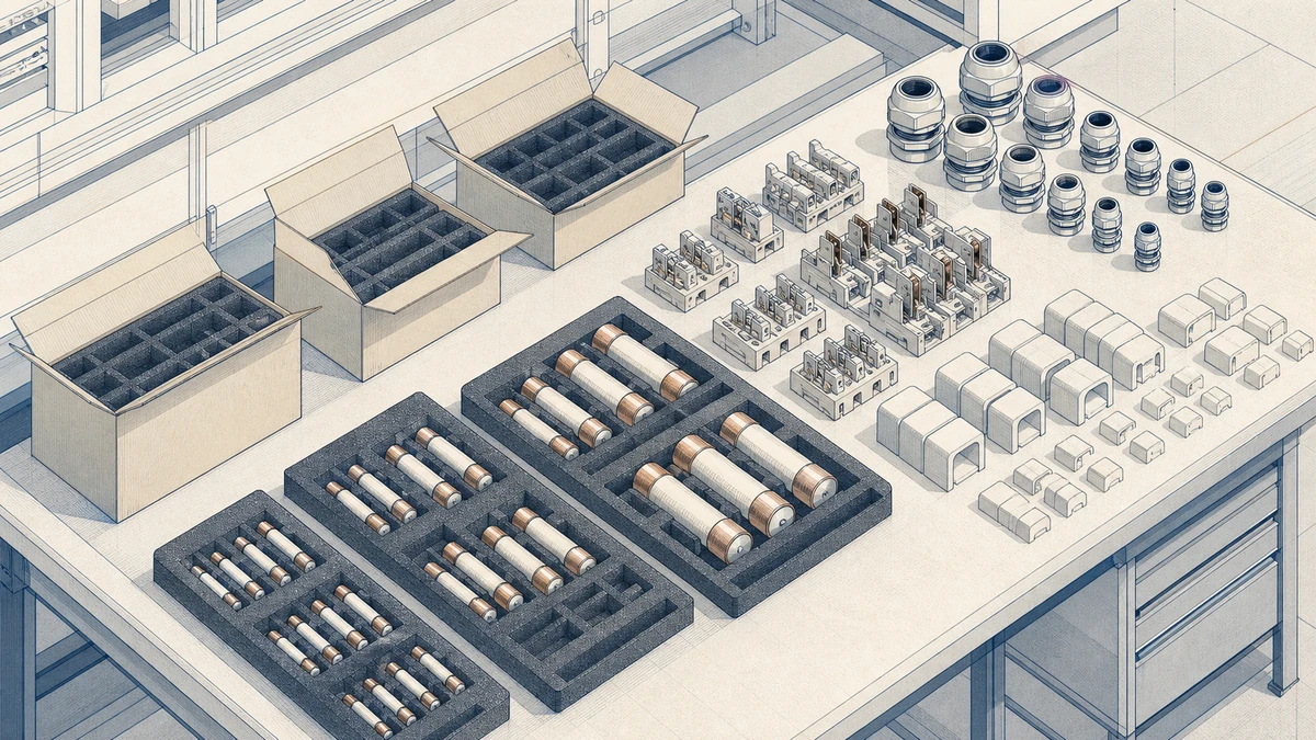
Consider a combiner box where multiple PV strings are connected in parallel. The normal string current may be close to the module short-circuit current under strong sunlight. At the same time, if one string becomes faulted, the remaining strings may feed reverse current into it.
The fuse must remain closed during the highest normal production condition but open when reverse current exceeds the safe limit for the module leads, connectors, or string conductors. The curve helps the designer compare these two conditions.
If the selected fuse rating is too low, it may open on hot days or during repeated current peaks. If the selected fuse rating is too high, a reverse-current fault may last too long. The correct selection sits between these risks and is confirmed using device-specific data.
A gPV fuse time current curve shows the relationship between current magnitude and fuse operating time for a photovoltaic fuse. It helps designers estimate whether the fuse will remain stable during normal PV operation and clear safely during overload or fault conditions.
No. A curve must be read for the exact fuse product family, current rating, and voltage duty. Curves are device-specific and should not be treated as universal across different DC fuse types, sizes, or manufacturers.
Possible causes include excessive ambient temperature, enclosure heating, undersized fuse rating, poor ventilation, repeated thermal cycling, loose connections, or normal operating current being too close to the fuse’s long-time operating region. A curve review and installation inspection are both needed to identify the cause.
A gPV fuse time current curve is essential for selecting PV DC protection that clears real faults without nuisance operation. It connects the electrical design to practical fuse behavior, especially in PV systems where high DC voltage and limited fault current make protection more demanding.
For Sinobreaker DC Fuse applications, the safest approach is to use the exact manufacturer curve, confirm voltage and breaking capacity, evaluate low-overcurrent behavior, and account for real installation conditions. The result is a protection design that supports both safety and long-term energy production.