Endereço
304 North Cardinal
St. Dorchester Center, MA 02124
Horas de trabalho
De segunda a sexta-feira: das 7h às 19h
Fim de semana: 10:00 - 17:00
Endereço
304 North Cardinal
St. Dorchester Center, MA 02124
Horas de trabalho
De segunda a sexta-feira: das 7h às 19h
Fim de semana: 10:00 - 17:00


PV surge protection system design is a critical engineering discipline that combines lightning physics, risk assessment methodology, and coordinated device selection to protect photovoltaic installations from transient overvoltages. As solar arrays expand in scale and reach higher voltages, systematic protection design becomes essential for ensuring equipment longevity and preventing catastrophic failures.
Modern DC SPD protection systems require a multi-layer approach integrating Type 1, Type 2, and Type 3 surge protective devices in coordinated configurations. The design process involves quantitative lightning risk assessment per IEC 62305-2, strategic SPD placement based on system topology, and proper grounding architecture to ensure effective energy dissipation.
This technical guide presents a comprehensive methodology for PV surge protection system design, covering lightning risk assessment calculations, energy coordination principles, and implementation strategies for both string inverter and central inverter architectures. You’ll learn how to calculate expected surge events, select appropriate protection levels, and design fail-safe systems that maintain protection integrity across the installation lifecycle.
💡 Engineering Foundation: Effective pv surge protection requires understanding that lightning protection is a system-level challenge, not simply installing individual SPD units—coordination between protection layers determines overall system survivability.
IEC 62305-2 provides a quantitative framework for calculating the annual probability of lightning-related damage to photovoltaic installations. This risk assessment determines the economic justification for lightning protection systems and guides SPD selection.
The total risk R equals the sum of risk components: R = R_A + R_B + R_C + R_M, where R_A relates to loss of human life, R_B to loss of service, and R_M to economic loss. Each component calculates from: R = N × P × L, where N is annual dangerous events, P is probability of damage, and L is consequent loss.
The expected number of direct strikes N_D to a PV installation depends on its equivalent collection area A_D: N_D = N_g × A_D × C_D × 10^-6 strikes per year. N_g represents ground flash density from regional isoceraunic maps, A_D is the collection area in m², and C_D is location coefficient (0.25-2.0 based on surroundings).
For a rectangular PV array: A_D = L × W + 2 × H × (L + W) + π × H², where L and W are array dimensions and H is height above ground. A 100m × 50m array at 2m height has A_D = 5,613 m². With N_g = 4 strikes/km²/year: N_D = 0.022 strikes/year (one strike every 45 years).
Near-miss strikes create induced surges. The annual number N_M typically exceeds direct strikes by 10-100×. For a 500m radius: A_M = π × 500² = 785,000 m², predicting N_M = 3.14 near strikes per year requiring SPD protection.
If calculated R > R_T (tolerable risk threshold of 10^-3 for economic loss), lightning protection measures are economically justified. Install coordinated pv surge protection if: N_g × (A_D + A_M) × P × L > R_T. This quantitative approach replaces subjective protection decisions with risk-based engineering.
🎯 Dica profissional: Document your IEC 62305-2 risk assessment calculations for insurance claims and warranty validation—quantitative justification proves protection systems were properly specified for site conditions.
Effective pv surge protection implements a coordinated three-layer defense strategy, with each layer providing specific protection characteristics optimized for different surge energy levels and system locations.
Type 1 SPDs install at the main electrical interface where external lightning protection system conductors connect to internal PV system wiring. These devices must withstand direct lightning currents with 10/350 μs waveform characteristics. Technical specifications include impulse current (I_imp) of 12.5-25 kA, discharge capacity of 100 kA (8/20 μs), and voltage protection level (Up) ≤4.0 kV for 1000V DC systems.
Type 1 devices typically use spark gap technology, providing high surge current capacity but slower response times compared to metal oxide varistors. Installation requires bonding where LPS down-conductors enter the structure.
Type 2 SPDs provide the primary protection layer in most PV installations, installed at Disjuntor CC panels and combiner box outputs. These devices protect against induced surges from nearby lightning strikes with discharge capacity of 20-40 kA (8/20 μs), voltage protection level ≤2.5 kV, and response time <25 ns.
Type 2 SPDs employ MOV technology, offering fast response and low voltage protection levels. Energy coordination requires proper separation distance (minimum 10m or 30 μH inductance) between Type 2 and downstream Type 3 devices.
Type 3 SPDs install at sensitive electronic equipment inputs with discharge capacity of 5 kA maximum, voltage protection level ≤1.5 kV, and response time <10 ns. These devices handle residual surge energy that passes through Type 2 protection using suppression diodes or fast-acting MOVs optimized for low clamping voltage.
| Parâmetro | Type 1 SPD | SPD Tipo 2 | Type 3 SPD |
|---|---|---|---|
| Função principal | Direct lightning current | Induced surge protection | Fine protection |
| Discharge Capacity | 100 kA (8/20 μs) | 20-40 kA (8/20 μs) | 5 kA (8/20 μs) |
| Nível de proteção de tensão | ≤4.0 kV | ≤2.5 kV | ≤1.5 kV |
| Tempo de resposta | <100 ns | <25 ns | <10 ns |
| Installation Location | LPS entry point | Inverter/combiner | Sensitive electronics |
Proper coordination relies on voltage selectivity (each upstream SPD must have higher protection voltage than downstream devices), series impedance (minimum 10m cable between layers), and energy sharing through parallel SPD units. Verify: E_Type2_letthrough < E_Type3_max to prevent downstream device overload.
String inverter systems require Type 2 SPD protection at each inverter DC input with discharge capacity of 20-40 kA depending on regional lightning density. String-level protection at combiners adds cost but intercepts surges before they propagate through long DC feeder cables.
AC-side SPDs at inverter outputs protect against utility-originated transients with minimum 20 kA discharge per mode. The SPD voltage protection level must activate before the inverter’s crowbar circuit: Up_SPD < 0.9 × V_crowbar.
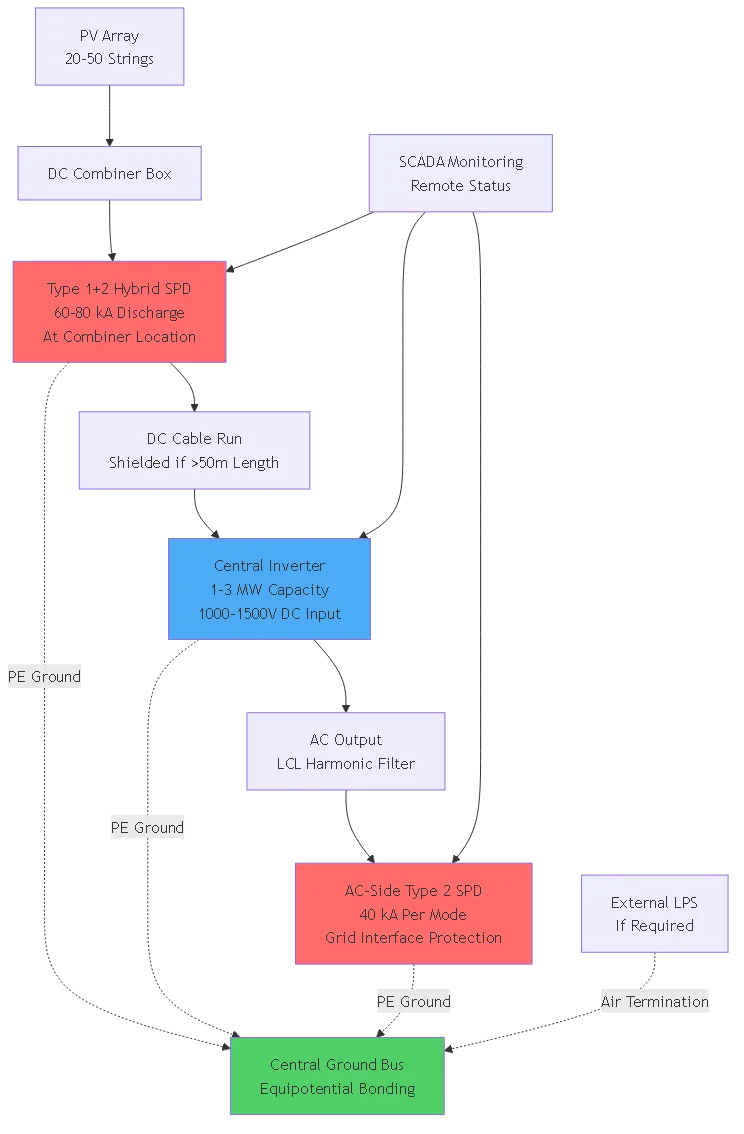
Central inverters require enhanced protection with Type 1+2 hybrid SPDs at the DC combiner rated 60-80 kA discharge capacity. Parallel SPD modules create N+1 redundancy and distribute discharge current. Remote monitoring via status contacts enables SCADA integration for large installations.
Voltage protection level coordination ensures: Up_Type1 > Up_Type2 > Up_equipment_rated with 15-20% steps. For 1500V systems: Type 1 Up ≤5.0 kV, Type 2 Up ≤3.5 kV, equipment withstand 1,800V minimum.
⚠️ Warning: Central inverter SPDs without remote monitoring leave expensive equipment vulnerable to undetected failures—implement quarterly testing or install status monitoring for systems >100 kW.

PV array mounting structures require dedicated grounding networks with driven ground rods at 8 ft (2.4m) depth, minimum 16 ft spacing, and interconnected via 4/0 AWG bare copper conductors. Target ground resistance: <5 Ω measured from furthest array section.
All ground rods must interconnect in mesh or ring configuration creating multiple parallel paths for surge dissipation. Radial grounding concentrates surge energy and causes excessive voltage rise.
SPD ground leads must minimize inductance as surge current through lead inductance creates voltage drop: V = L × (di/dt). Even 1 μH inductance produces 10 kV with 10 kA/μs current rise rates.
Best practices include: minimum 30 cm (12 inch) total length, 10 AWG minimum (6 AWG for Type 1), straight routing without loops, direct busbar mounting where possible. Measure ground connection resistance from each SPD terminal to main reference—values should not exceed 0.1 Ω.
Large distributed arrays require equipotential bonding zones of 30-50m maximum dimension. Each zone includes heavy copper ground bus (min 100 mm² cross-section) with 10 AWG bonding conductors between zones. This configuration equalizes potential across zones during surge events.
Implement single-point or star grounding topology where all SPDs and equipment connect to central ground bus. For distributed arrays, use dedicated ground conductors that don’t interconnect at intermediate points. Verify <0.1 Ω resistance between AC and DC ground points.
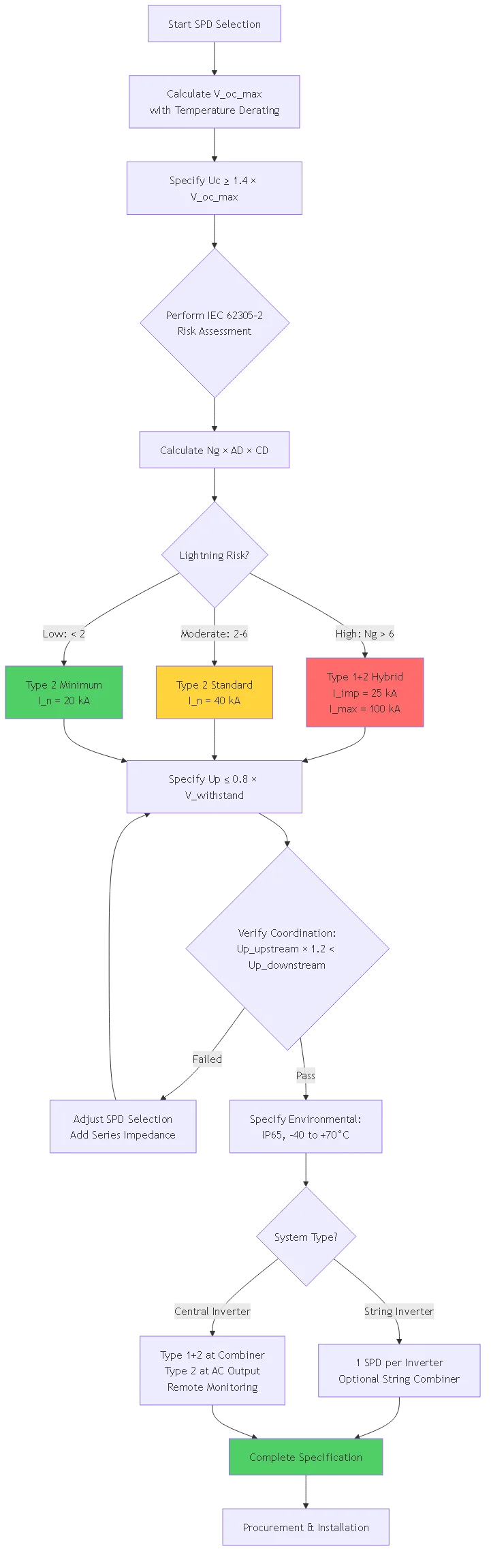
The SPD’s U_c must exceed maximum steady-state voltage under all conditions. For DC-side SPDs: U_c ≥ 1.4 × V_oc_max, where V_oc_max includes temperature derating: V_oc_max = V_oc_STC × (1 + α_V × ΔT).
Example for 1000V system: String V_oc = 750V at 25°C, temperature coefficient α_V = -0.3%/°C, minimum ambient -40°C. V_oc_max = 750 × (1 + (-0.003 × -65)) = 896V. Required U_c: 1.4 × 896 = 1,254V, select SPD rated U_c = 1,300V DC minimum.
High-lightning regions (N_g > 6) require Type 1 SPDs with I_imp ≥25 kA (10/350 μs) and Type 2 SPDs with I_n ≥40 kA (8/20 μs). Moderate regions (2 < N_g < 6) can use Type 2 SPDs at I_n ≥20 kA. Low-lightning regions (N_g < 2) accept I_n = 10-15 kA minimum.
SPD voltage protection level must remain below equipment withstand voltage with adequate margin: U_p < 0.8 × V_withstand. For 8 kV inverter withstand, select SPDs with U_p ≤2.5 kV providing 3× safety margin.
Verify coordination: U_p_upstream × 1.2 < U_p_downstream ensuring 20% voltage separation between layers.
Outdoor SPD enclosures require IP65 minimum (NEMA 3R), UV-stabilized materials, -40°C to +70°C operating temperature, and salt spray resistance for coastal locations. At elevations above 2000m, apply derating: Capacity_effective = Capacity_rated × (2000m / Altitude)^0.9.
Verify SPD mounting security, conductor terminations, ground lead routing (minimum length, straight path), polarity, environmental sealing, and status indicator operation. Use continuity tester to confirm SPD not failed open-circuit before energization.
Measure pole-to-ground resistance with megohmmeter at 1000V DC test voltage. Reading should exceed 1 MΩ without SPDs, >100 kΩ with SPDs connected. Insulation resistance drop from SPD connection should not exceed 90%.
Use fall-of-potential tester to measure resistance from ground electrode to remote earth. Acceptance criteria: individual electrodes <25 Ω per nec 250.53(a)(2), system resistance <5 for optimal protection, inter-zone <1 Ω.
Install current probes on upstream and downstream SPD ground leads. Apply surge at 50% of downstream SPD rated current—verify upstream SPD conducts >80% of total surge current, confirming proper coordination.
Problema: Installing SPDs with U_c below maximum system voltage causes premature aging or immediate failure during cold weather when V_oc peaks.
Common scenarios: Selecting 1000V SPD for 1000V system without temperature derating margin, failing to account for series string voltages, using AC-rated SPDs on DC systems.
Correção: Calculate maximum V_oc including -40°C temperature coefficient, select SPD with U_c ≥1.4 × V_oc_max. For 1000V systems, use 1,300-1,500V rated SPDs minimum.
Problema: Long ground leads create inductive voltage drop during surge discharge: V = L × (di/dt). A 1m ground lead (1 μH/m) × 10 kA/μs = 10 kV added voltage, defeating protection.
Correção: Limit ground leads to <30 cm maximum length, route in straight line with no loops, use minimum 6 awg conductors, mount spds directly on ground busbar when possible.
Problema: Installing Type 2 and Type 3 SPDs too close without adequate series impedance causes downstream device overload and destruction.
Correção: Maintain minimum 10m cable length (30 μH inductance) between SPD layers, verify voltage protection level coordination with 15-20% steps, never install Type 3 without upstream Type 2 protection.
Problema: Connecting equipment to multiple ground points at different potentials creates circulating currents through electronics during surge events.
Correção: Implement single-point or star grounding topology, interconnect all ground electrodes with 4/0 AWG conductors, create equipotential bonding zones for distributed arrays, verify <0.1 Ω resistance between ground points.
⚠️ Crítico: Failed SPDs often fail open-circuit without visible indication. Implement quarterly testing or remote monitoring to detect failures before subsequent surges destroy unprotected equipment.
Type 1, Type 2, and Type 3 SPDs differ primarily in energy handling capacity, voltage protection level, and installation location. Type 1 SPDs handle direct lightning strikes with impulse currents up to 25 kA (10/350 μs) and install where external LPS conductors enter the structure. Type 2 SPDs protect against induced surges with 20-40 kA discharge capacity (8/20 μs) and install at inverter inputs as the primary protection layer. Type 3 SPDs provide final protection for sensitive electronics with 5 kA capacity but lowest voltage protection level (≤1.5 kV). Proper coordination between layers ensures upstream devices handle high-energy surges while downstream devices provide tighter voltage clamping for semiconductor protection.
Calculate the SPD’s continuous operating voltage (U_c) by first determining maximum array open-circuit voltage under worst-case cold conditions. Use the formula: V_oc_max = V_oc_STC × (1 + α_V × ΔT), where α_V is the temperature coefficient (typically -0.3%/°C) and ΔT is temperature difference from STC (typically -65°C for -40°C minimum ambient). The minimum SPD rating should be U_c ≥1.4 × V_oc_max. For example, an 18-series string with 40V modules gives V_oc_STC = 720V. Temperature derating: 720V × 1.195 = 860V. Required U_c: 1.4 × 860V = 1,204V, so select SPD rated ≥1,300V DC. The 1.4× safety factor accounts for temporary overvoltage and SPD aging.
String inverter systems typically require 20-40 kA (8/20 μs) discharge capacity per inverter input depending on regional lightning density. In high-lightning regions (N_g > 6 strikes/km²/year) with string combiners serving 4-8 parallel strings, specify 40 kA minimum. Central inverter systems demand 60-80 kA at the main DC combiner due to concentrated surge energy from 20-50 parallel strings. Use Type 1+2 hybrid SPDs combining 25 kA impulse current (10/350 μs) with 60-80 kA discharge (8/20 μs) for central systems. Alternatively, install multiple 40 kA SPDs in parallel providing equivalent capacity with failure redundancy. Always maintain 25% safety margin above calculated worst-case surge energy.
Prevent ground loops by implementing single-point grounding topology where all SPDs and equipment connect to a central ground bus at the inverter location using dedicated conductors that don’t interconnect at intermediate points. For distributed arrays exceeding 50m, create equipotential bonding zones of 30-50m maximum dimension, each with heavy copper ground bus (100 mm² minimum) interconnected via multiple parallel 10 AWG bonding conductors. During surge events, these zones equalize potential before differences can stress equipment. Ensure all ground electrodes interconnect in mesh configuration, bond AC and DC ground systems together at the inverter using 6 AWG minimum, and verify <0.1 Ω resistance between AC and DC ground points. Never connect equipment frame ground to multiple points along its length.
External LPS becomes necessary when IEC 62305-2 risk assessment identifies unacceptable direct strike probability, typically required for arrays exceeding 8-10m height in regions with N_g > 4 strikes/km²/year. Calculate annual direct strikes: N_D = N_g × A_D × C_D × 10^-6, where A_D is the structure’s collection area. If N_D > 0.05 (strike expected more than once per 20 years), external LPS proves economically justified for installations valued over $500,000. Integration requires coordinated design with air termination intercepting strikes, down-conductors carrying current to ground, and Type 1 SPDs (I_imp = 25 kA minimum) at electrical interfaces where LPS bonds to grounding system. Without external LPS, protection relies entirely on Type 2 SPDs, adequate for most ground-mounted arrays under 4m height.
Implement quarterly visual inspection verifying status indicators show operational state, no visible damage to enclosures or connections, mounting hardware torque-verified, no overheating evidence, and seals intact. Annual electrical testing includes: measuring leakage current at rated voltage (baseline <1 ma, replace if>5 mA or 50% increase), testing ground connection resistance (<0.1 Ω required), verifying insulation resistance between protected conductors (>1 MΩ), and measuring pole-to-ground resistance with SPDs connected (>100 kΩ for ground fault detection function). Document measurements for trending analysis—gradual increases indicate approaching end-of-life. Replace SPDs immediately after significant lightning strikes even if tests pass. Implement 10-year maximum replacement for Type 2 SPDs regardless of test results.
Ensure AC-side SPDs don’t interfere with anti-islanding detection by specifying MOV-based devices with <100 pf capacitance and>100 kΩ resistance at nominal voltage, remaining transparent to frequency shift or impedance measurement anti-islanding methods. SPD voltage protection level must coordinate with inverter overvoltage trip settings: select Up = 1.5-2.0× nominal voltage to clamp surges while remaining below inverter trip point (typically 1.35× nominal). For ground fault detection integration, use SPDs with high DC resistance (>100 kΩ) between conductors and ground, or implement CT-based detection subtracting known SPD leakage from total ground current. Verify SPD installation maintains >100 kΩ combined pole-to-ground resistance. Document baseline leakage currents and configure ground fault trip thresholds above this baseline (typically 300-500 mA) while maintaining 30 mA personnel protection sensitivity. Request utility pre-approval of SPD specifications during interconnection application for installations exceeding 1 MW.
Effective pv surge protection system design integrates quantitative lightning risk assessment, coordinated multi-layer SPD placement, and comprehensive grounding architecture to protect photovoltaic installations from transient overvoltages across their operational lifetime. The systematic approach presented ensures protection strategies align with site-specific lightning exposure while maintaining economic viability through risk-based design decisions.
Principais conclusões:
1. IEC 62305-2 risk assessment provides quantitative justification for protection investment by calculating expected surge events and economic consequences.
2. Multi-layer protection using coordinated Type 1, Type 2, and Type 3 SPDs creates cascading defense handling both high-energy direct strikes and low-level induced transients.
3. Grounding system design with equipotential bonding zones and low-impedance connections ensures effective surge energy dissipation without creating damaging potential differences.
4. System-specific strategies vary between string and central inverter architectures, with central systems requiring enhanced SPD ratings and redundant configurations.
5. Lifecycle maintenance validates continued protection effectiveness through quarterly inspection and annual electrical testing, enabling proactive replacement before catastrophic failure.
Related Resources:
– DC SPD Technology and Selection Guide
– PV Combiner Box Protection Systems
– DC Switch Disconnector Integration
Ready to implement comprehensive pv surge protection for your installation? Contact SYNODE’s technical team for project-specific lightning risk assessment and coordinated SPD system design. We provide detailed calculations per IEC 62305-2, specify appropriate protection devices for your system topology, and ensure proper coordination with existing overcurrent protection and grounding systems to maximize equipment protection while maintaining long-term reliability.
Última atualização: Outubro de 2025
Autor: Equipe técnica do SYNODE
Avaliado por: Departamento de Engenharia Elétrica
Palavra-chave de foco: pv surge protection
URL Slug: pv-surge-protection-system-design-lightning-risk
Meta Título: PV Surge Protection System Design: Lightning Risk Assessment Guide 2025
Meta Descrição: Complete pv surge protection system design guide covering IEC 62305 lightning risk assessment, SPD coordination, and multi-layer protection strategies for solar installations.
Nível de conteúdo: Tier 3 (Supporting Content)
Funil de conversão: Top of Funnel (Awareness)
Contagem de palavras-alvo: 2800-4000 palavras
Diagramas da sereia-alvo: 3
Configure-os nas definições do Rank Math e, em seguida, exclua esta caixa antes de publicar.
Type 1, Type 2, and Type 3 SPDs differ primarily in energy handling capacity, voltage protection level, and installation location. Type 1 SPDs handle direct lightning strikes with impulse currents up to 25 kA (10/350 μs) and install where external LPS conductors enter the structure. Type 2 SPDs protect against induced surges with 20-40 kA discharge capacity (8/20 μs) and install at inverter inputs as the primary protection layer. Type 3 SPDs provide final protection for sensitive electronics with 5 kA capacity but lowest voltage protection level (≤1.5 kV). Proper coordination between layers ensures upstream devices handle high-energy surges while downstream devices provide tighter voltage clamping.
Calculate the SPD’s continuous operating voltage (U_c) by first determining maximum array open-circuit voltage under worst-case cold conditions. Use the formula: V_oc_max = V_oc_STC × (1 + α_V × ΔT), where α_V is the temperature coefficient (typically -0.3%/°C) and ΔT is temperature difference from STC (typically -65°C for -40°C minimum ambient). The minimum SPD rating should be U_c ≥1.4 × V_oc_max. The 1.4× safety factor accounts for temporary overvoltage and SPD aging.
String inverter systems typically require 20-40 kA (8/20 μs) discharge capacity per inverter input depending on regional lightning density. In high-lightning regions (N_g > 6 strikes/km²/year) with string combiners serving 4-8 parallel strings, specify 40 kA minimum. Central inverter systems demand 60-80 kA at the main DC combiner due to concentrated surge energy from 20-50 parallel strings. Use Type 1+2 hybrid SPDs combining 25 kA impulse current (10/350 μs) with 60-80 kA discharge (8/20 μs) for central systems.
Prevent ground loops by implementing single-point grounding topology where all SPDs and equipment connect to a central ground bus at the inverter location using dedicated conductors that don’t interconnect at intermediate points. For distributed arrays exceeding 50m, create equipotential bonding zones of 30-50m maximum dimension, each with heavy copper ground bus (100 mm² minimum) interconnected via multiple parallel 10 AWG bonding conductors. Ensure all ground electrodes interconnect in mesh configuration and bond AC and DC ground systems together at the inverter.
External LPS becomes necessary when IEC 62305-2 risk assessment identifies unacceptable direct strike probability, typically required for arrays exceeding 8-10m height in regions with N_g > 4 strikes/km²/year. Calculate annual direct strikes: N_D = N_g × A_D × C_D × 10^-6. If N_D > 0.05 (strike expected more than once per 20 years), external LPS proves economically justified for installations valued over $500,000. Integration requires Type 1 SPDs (I_imp = 25 kA minimum) at electrical interfaces where LPS bonds to grounding system.
Implement quarterly visual inspection and annual electrical testing. Annual tests include: measuring leakage current at rated voltage (baseline <1 ma, replace if>5 mA or 50% increase), testing ground connection resistance (<0.1 Ω required), verifying insulation resistance between protected conductors (>1 MΩ), and measuring pole-to-ground resistance with SPDs connected (>100 kΩ). Document measurements for trending analysis. Replace SPDs immediately after significant lightning strikes. Implement 10-year maximum replacement for Type 2 SPDs regardless of test results.
Ensure AC-side SPDs don’t interfere with anti-islanding detection by specifying MOV-based devices with <100 pf capacitance and>100 kΩ resistance at nominal voltage. SPD voltage protection level must coordinate with inverter overvoltage trip settings: select Up = 1.5-2.0× nominal voltage. For ground fault detection integration, use SPDs with high DC resistance (>100 kΩ) between conductors and ground. Verify SPD installation maintains >100 kΩ combined pole-to-ground resistance. Document baseline leakage currents and configure ground fault trip thresholds above this baseline.