Adresse
304 Nord Kardinal
St. Dorchester Center, MA 02124
Arbeitszeiten
Montag bis Freitag: 7AM - 7PM
Am Wochenende: 10AM - 5PM
Adresse
304 Nord Kardinal
St. Dorchester Center, MA 02124
Arbeitszeiten
Montag bis Freitag: 7AM - 7PM
Am Wochenende: 10AM - 5PM


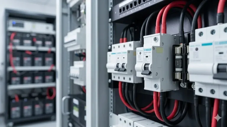
200 amp DC circuit breakers represent the threshold between residential and industrial-grade electrical protection. These high-current devices protect large solar inverters, marine windlass systems, electric vehicle chargers, and battery banks where lower-rated breakers would fail.
This technical guide explores the engineering principles, thermal characteristics, and application-specific considerations that distinguish 200A DC breakers from their lower-rated counterparts.
The 200 ampere rating sits at a unique intersection in DC electrical systems:
Physical Characteristics:
- Größe der Klemme: Requires 2/0 AWG to 4/0 AWG conductors
- Contact surface area: 10-15× larger than 20A breakers
- Heat dissipation: 40× thermal energy at rated current
- Lichtbogenunterbrechung: Requires advanced magnetic blowout chambers
- Montage: Surface or bolt-on; too large for DIN rail
Application Boundaries:
– Below 200A: Residential solar (up to ~10kW inverter at 48V)
– At 200A: Large residential solar (9.6kW @ 48V), marine windlass
– Above 200A: Commercial solar, industrial battery systems, EV fast charging
Engineering Considerations:
– Short-circuit current rating (SCCR): Must handle 5,000-10,000A faults
– Voltage rating: Typically 32V, 80V, 125V, or 150V DC maximum
– Temperature derating: Significant capacity reduction above 40°C ambient
– Conductor losses: 0.5-1.0V drop at full 200A load if connections imperfect
A 200A DC breaker’s trip behavior follows precise time-current curves:
Thermal Trip Region (100-200% overload):
110% (220A): 60-120 minutes to trip
120% (240A): 20-40 minutes to trip
135% (270A): 4-8 minutes to trip
150% (300A): 1-3 minutes to trip
200% (400A): 10-30 seconds to trip
Magnetic Trip Region (>200% overload):
300% (600A): 2-5 seconds
500% (1000A): 0.5-2 seconds
1000% (2000A): 0.1-0.5 seconds (short circuit)
Why These Curves Matter:
The thermal region protects against sustained overloads where the load exceeds capacity but hasn’t failed catastrophically. Example: A 160A inverter drawing 220A continuously for several minutes due to heavy loads.
The magnetic region provides fast protection against short circuits where fault current could exceed 2000A in milliseconds, potentially causing arc flash or conductor melting.
Definition: Maximum current the breaker can safely interrupt without damage or fire.
Typical 200A DC Breaker Ratings:
- Standard duty: 5,000 AIC (5kA)
- Medium duty: 10,000 AIC (10kA)
- Heavy duty: 25,000 AIC (25kA)
- Industriell: 50,000+ AIC (50kA+)
How to Calculate Required AIC:
The available fault current depends on your battery bank’s capacity and internal resistance:
Fault Current (A) = Battery Voltage (V) / Total Circuit Resistance (Ω)Example: 48V battery bank, 200Ah lithium Battery internal resistance: ~0.010Ω Wire resistance (5 ft of 2/0 AWG): 0.00006Ω per foot × 5 × 2 = 0.0006Ω Connection resistance: 0.001Ω (typical) Total resistance: 0.010 + 0.0006 + 0.001 = 0.0116Ω
Fault current = 48V / 0.0116Ω = 4,138A
Required breaker: 5,000 AIC minimum (select 10,000 AIC for safety margin)
Wichtig: Lithium batteries have extremely low internal resistance and can deliver massive fault currents. AGM/flooded lead-acid batteries have higher internal resistance (~0.050Ω), limiting fault current to ~1,000A.
Common DC Voltage Ratings for 200 Amp DC Circuit Breaker:
| Nennspannung | Typische Anwendungen | Arc Gap Distance |
|---|---|---|
| 32V DC | 12V/24V automotive, marine | 1-2mm |
| 80V DC | 48V solar residential | 3-4mm |
| 125V DC | 120V battery systems, telecom | 5-6mm |
| 150V DC | Commercial solar strings | 6-8mm |
| 600V DC | Utility-scale solar | 15-20mm |
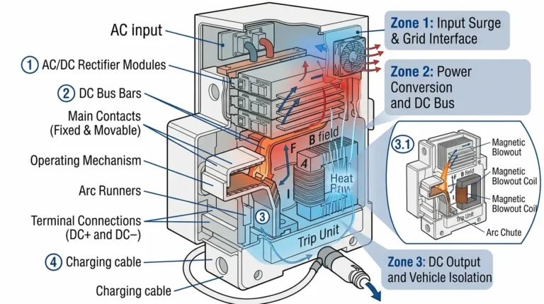
Why Voltage Matters for DC Breakers:
Unlike AC where the arc self-extinguishes at zero crossing (120 times per second at 60Hz), DC arcs sustain indefinitely. Higher voltage requires:
– Larger contact gap spacing
– Magnetic blowout coils to stretch arc
– Arc chutes to divide arc into smaller sections
– Heavier spring pressure to separate contacts quickly
Critical Safety Rule: Never use a breaker rated below your system’s maximum voltage, including charging voltages. A 48V system with 58.4V float charge requires minimum 80V DC rated breaker, not 48V.
200 Amp DC Circuit Breaker generate significant internal heat through I²R losses. Ambient temperature directly affects capacity:
Derating Table (typical thermal-magnetic breaker):
| Temperatur in der Umgebung | Rated Current Capacity |
|---|---|
| -20°C (-4°F) | 105% (210A) |
| 0°C (32°F) | 102% (204A) |
| 25°C (77°F) | 100% (200A) – Standard rating |
| 40°C (104°F) | 95% (190A) |
| 50°C (122°F) | 90% (180A) |
| 60°C (140°F) | 85% (170A) |
| 70°C (158°F) | 80% (160A) |
Praktisches Beispiel:
Solar inverter in Arizona attic:
– Inverter rated: 9.6kW @ 48V = 200A
– Attic temperature: 55°C (131°F)
– Breaker derating: ~88%
– Effective capacity: 200A × 0.88 = 176A
- Ergebnis: 200A breaker will nuisance trip; need 250A breaker
Solution Strategies:
1. Improve ventilation (reduce ambient temperature)
2. Mount breaker in cooler location
3. Upsize breaker to 250A to compensate
4. Use hydraulic-magnetic breaker (no thermal derating)

NEC Table 310.16 (75°C rated wire, copper, 30°C ambient):
| Drahtgröße | Ampacity | Suitable for 200A? | Typische Verwendung |
|---|---|---|---|
| 3/0 AWG | 200A | Yes (exactly matched) | Mindestgröße |
| 4/0 AWG | 230A | Yes (preferred) | Standard installation |
| 250 kcmil | 255A | Yes (15% margin) | Hot environments |
| 300 kcmil | 285A | Yes (42% margin) | Long runs, derating |
| 350 kcmil | 310A | Yes (55% margin) | Future-proof |
Critical Considerations:
1. 125% Rule for Continuous Loads (NEC 690.8):
“`
If inverter runs >3 hours continuously:
Required wire ampacity = 200A × 1.25 = 250A
Select: 250 kcmil minimum
“`
2. Bundling/Conduit Derating:
“`
4-6 current-carrying conductors: 80% capacity
7-9 conductors: 70% capacity
Example: 4/0 AWG (230A rated) × 0.80 = 184A derated
Result: Insufficient for 200A breaker; upsize to 250 kcmil
“`
3. Temperatur-Derating:
“`
40°C ambient: 4/0 AWG × 0.91 = 209A
50°C ambient: 4/0 AWG × 0.82 = 189A (insufficient)
“`
200 Amp DC Circuit Breaker require specialized termination:
Method 1: Compression Lug Termination (Preferred)
– Use hydraulic crimper (standard die)
– Copper compression lugs rated 200A continuous
– Apply anti-oxidant compound before crimping
– Heat shrink over connection for moisture protection
– Torque to manufacturer specification: 200-300 in-lbs typical
Method 2: Mechanical Lug (Set-Screw)
– Two-screw design minimum for 200A
– Requires stranded wire (not solid)
– Apply anti-oxidant compound
– Torque both screws evenly
– Periodic retorque required (annually)
Method 3: Bolted Bus Connection
– Direct bolt to busbar
– Multiple bolts for current distribution
– Belleville washers prevent loosening
– Torque specification: 25-35 ft-lbs typical
Connection Resistance Target:
– Maximum: 50 microohms (0.00005Ω)
– At 200A: Power loss = I²R = (200)² × 0.00005 = 2W per connection
– Temperature rise: ~5°C acceptable
– Poor connection (500 microohms): 20W loss, 50°C rise – FAILURE
Testing Connection Quality:
1. Visual inspection (no gaps, corrosion)
2. Torque verification with calibrated wrench
3. Voltage drop measurement (should be <0.1V at full load) 4. Thermal imaging (connection should not exceed breaker body temperature)

Typical 200A Application: 9.6kW inverter at 48V nominal
Key Design Parameters:
1. Inverter Surge Current:
– Steady state: 9600W ÷ 48V = 200A
– Startup surge: 1.5-2.0× rated = 300-400A for 1-5 seconds
– Breaker must NOT trip on startup surge
– Solution: Select breaker with 300A instantaneous rating
2. Battery Voltage Variation:
“`
48V system actual voltage range:
– Full charge: 58.4V (LiFePO4)
– Nominal: 51.2V
– Low voltage cutoff: 44V
Inverter current at low voltage:
9600W ÷ 44V = 218A (9% above rating!)
Breaker sizing: Must accommodate 218A continuously
Select 250A breaker OR current-limit inverter output
“`
3. Wire Routing:
– Keep main DC cables <10 feet to minimize voltage drop – Each 1% voltage drop wastes 96W at 9.6kW – Use same gauge for positive and negative – Route cables away from heat sources
4. Grounding Requirements (NEC 690.41):
– Array grounding required for most systems
– Battery system may be grounded or floating
– If grounded: Bond negative to ground at ONE point only
– Ground fault protection required for some systems
Typical 200A Application: 12V electric anchor windlass (2400W)
Unique Marine Challenges:
1. Intermittent High Current:
– Windlass pulls chain: 150-250A for 30-120 seconds
– Thermal trip must tolerate surge without nuisance trips
– Select breaker with high instantaneous rating (400A+)
2. Voltage Drop Critical:
“`
Windlass motor sensitivity:
At 10V (instead of 12V): 30% torque reduction
Maximum acceptable drop: 1.0V (8.3%)
Example: 20-foot cable run at 200A
Required resistance: 1.0V ÷ 200A = 0.005Ω total
Cable resistance: 0.005Ω ÷ (2 × 20 ft) = 0.000125 Ω/ft
Wire requirement: 2/0 AWG minimum (0.0001 Ω/ft)
Better: 4/0 AWG (0.0000806 Ω/ft) = 0.64V drop
“`
3. Corrosion Protection:
– Tinned copper wire mandatory
– Stainless steel or gold-plated terminals
– Conformal coating on breaker internals
– IP67-rated breaker enclosure
– Annual inspection and cleaning
4. Ignition Protection (ABYC E-11.17):
– Windlass typically in non-hazardous space
– If near gasoline engine: Ignition-protected breaker required
– Sealed breaker housing prevents spark ignition
Anmeldung: 200Ah+ lithium battery bank disconnector
Critical Safety Functions:
1. Emergency Shutdown:
– Must be accessible in <5 seconds – Red handle or paddle-style actuator – Labeled “MAIN BATTERY DISCONNECT” – Located within sight of battery
2. Wartung Isolierung:
– Zero voltage verification after opening
– Lockout/tagout capability (padlock hasp)
– Visible open/closed indication
3. BMS Integration:
– Battery Management System may command disconnect
– Some 200A breakers offer shunt trip coil (24V/48V DC)
– Shunt trip opens breaker remotely for over-temperature, over-voltage
4. Paralleled Battery Banks:
“`
Two 100Ah batteries in parallel = 200Ah total
Each battery has 100A continuous, 200A surge capability
Combined: 200A continuous, 400A surge
Breaker sizing:
– Main breaker: 200A (matches combined continuous)
– Individual battery breakers: 125A (matches single battery × 1.25)
“`
Thermal-Magnetic (Standard)
Operating Principle:
– Bi-metal strip heats with current
– Magnetic coil for fast short-circuit trip
– Combined time-delay and instantaneous protection
Vorteile:
– Lower cost ($80-150 typical)
– Widely available
– Simple operation
Benachteiligungen:
– Sensitive to ambient temperature (requires derating)
– Trip point drifts with age
– Not suitable for high-cycle applications
Am besten für: Standard solar inverters, fixed installations, moderate ambient temperatures
Hydraulic-Magnetic (Premium)
Operating Principle:
– Hydraulic fluid dashpot provides time delay
– Magnetic core for instantaneous trip
– Temperature-compensated design
Vorteile:
– No thermal derating (maintains 200A to 70°C)
– Precise trip point (±5% vs. ±20% for thermal)
– Long cycle life (50,000+ operations)
– Immune to ambient temperature
Benachteiligungen:
– Higher cost ($200-400 typical)
– Limited availability
– Requires specific mounting orientation (fluid-based)
Am besten für: Marine applications, hot environments (engine rooms), frequent cycling loads (windlass, thrusters)
Comparison Table:
| Merkmal | Thermal-Magnetic | Hydraulic-Magnetic |
|---|---|---|
| Kosten | $80-150 | $200-400 |
| Temperature derating | Yes (15-20% at 60°C) | Keine |
| Trip accuracy | ±20% | ±5% |
| Cycle life | 5,000-10,000 | 50,000+ |
| Wartung | Rare | Keine |
| Ambient temp range | -20°C to 60°C | -40°C to 80°C |
| Best use | Fixed solar inverter | Marine windlass/thruster |
Operating Principle:
– Current sensor (shunt or Hall effect)
– Microprocessor trip logic
– Electronic solenoid trip mechanism
Vorteile:
– Programmable trip curves
– Remote monitoring capability
– Precise trip points (±2%)
– Multiple protection modes (overcurrent, under-voltage, reverse polarity)
– Data logging
Benachteiligungen:
– Requires auxiliary power (parasitic draw 1-5W)
– More complex (more failure modes)
– Higher cost ($300-600)
– May fail in harsh environments
Am besten für: Industrial systems, remote monitoring requirements, systems with BMS integration

Mounting Requirements:
1. Brecher-Ausrichtung:
– Thermal-magnetic: Vertical mounting preferred (heat rises naturally)
– Horizontal mounting: Derate 5-10%
– Upside-down: Not recommended (heat affects trip mechanism)
– Hydraulic-magnetic: Must follow manufacturer orientation (fluid-based)
2. Clearances:
– Top: 3 inches minimum (heat dissipation)
– Sides: 2 inches (air circulation)
– Working space: 36 inches depth × 30 inches width (NEC 110.26)
3. Structural Support:
– Breaker weight: 3-5 lbs typical
– Conductor weight: 1-2 lbs per foot for 4/0 AWG
– Total system weight: 10-20 lbs
– Mount to structural member, not drywall
4. Vibration Isolation (Marine/RV):
– Use rubber isolators or vibration pads
– Prevent connection loosening from vibration
– Check torque quarterly in high-vibration environments
Torque Specifications:
Proper torque prevents:
– Loose connections → high resistance → heating → fire
– Over-torque → damaged threads → loose over time
| Terminal Size | Spezifikation des Drehmoments |
|---|---|
| 200A lug (2/0-4/0 AWG) | 250-350 in-lbs (21-29 ft-lbs) |
| Busbar connection | 300-400 in-lbs (25-33 ft-lbs) |
| Ground lug | 150-200 in-lbs (12-17 ft-lbs) |
Torque Procedure:
1. Clean terminal surfaces (ScotchBrite pad)
2. Apply anti-oxidant compound
3. Insert conductor fully into lug
4. Torque in stages: 50% → 75% → 100%
5. Verify no conductor movement
6. Mark with torque seal paint
7. Re-torque after 24 hours (initial settling)
Cable Dressing:
Best Practices:
- Minimum bend radius: 10× cable diameter
  (4/0 AWG = 0.528" diameter → 5.28" minimum bend)
- Support cables every 18-24 inches
- Avoid sharp bends (creates stress points)
- Route positive and negative together (minimize inductance)
- Keep away from heat sources (exhaust, engines)
- Use cable glands for enclosure penetrations
Pre-Energization Tests:
1. Visual Inspection Checklist:
– [ ] All terminations torqued to specification
– [ ] No exposed conductors
– [ ] Proper wire gauge installed
– [ ] Polarity marked correctly (+/-)
– [ ] Breaker rated for system voltage
– [ ] Breaker labeled with circuit name and amperage
– [ ] Clearances maintained
– [ ] Mounting secure
2. Prüfung des Isolationswiderstands (Megohmmeter):
“`
Testverfahren:
– Disconnect load and source
– Set megger to 500V DC test voltage
– Measure positive to ground: Should be >1 MΩ
– Measure negative to ground: Should be >1 MΩ
– Measure positive to negative: Should be >1 MΩ (with load disconnected)
If <1 MΩ: Indicates insulation breakdown or moisture “`
3. Continuity Test:
“`
With multimeter in resistance mode:
– Breaker OPEN: Should read infinite resistance (OL)
– Breaker CLOSED: Should read <0.001Ω (essentially 0Ω)
High resistance when closed: Poor internal contact, replace breaker
“`
4. Voltage Drop Test:
“`
With breaker closed and load energized at 80% (160A):
– Measure voltage at breaker input
– Measure voltage at breaker output
– Calculate drop: Should be <0.2V
If >0.5V: Indicates loose connections or undersized breaker
“`
Post-Energization Tests:
1. Thermal Imaging (After 1 hour at 80% load):
– Breaker body temperature: <60°C above ambient acceptable – Terminal connections: Should match breaker body temperature (±5°C) – Hot spots indicate problems: Retorque connections
2. Trip Test (If Feasible):
“`
Caution: May damage load if performed incorrectly
Verfahren:
1. Gradually increase load to 135% (270A)
2. Breaker should trip in 4-8 minutes
3. If trips too fast: Breaker undersized or faulty
4. If doesn’t trip: Breaker oversized or faulty
Note: Most installations skip this test; rely on manufacturer testing
“`
Quarterly (Marine/RV) or Semi-Annually (Fixed Installation):
- Sichtprüfung auf Korrosion
– Torque check on all connections (may loosen over time)
– Clean external surfaces
– Verify breaker resets smoothly
– Check for unusual heat or odors
Jährlich:
– Thermal imaging under load
– Insulation resistance test
– Voltage drop measurement
– Clean terminal surfaces and reapply anti-oxidant compound
– Document findings
Problem 1: Breaker Trips at 70-80% Load
Possible Causes:
1. Ambient temperature too high (thermal derating)
2. Poor ventilation around breaker
3. Breaker nearing end of life (trip point drifts lower)
4. Loose connections creating extra heat
Diagnostische Schritte:
1. Measure actual current with DC clamp meter
2. Measure ambient temperature near breaker
3. Calculate derated capacity
4. Check voltage drop across breaker (>0.5V indicates problem)
5. Thermal image connections
Lösungen:
– Improve ventilation or relocate breaker
– Upsize to 250A breaker
– Replace aging breaker
– Retorque connections
Problem 2: Breaker Doesn’t Trip During Obvious Overload
Possible Causes:
1. Breaker oversized for actual load
2. Breaker failure (welded contacts)
3. Measuring current incorrectly
Diagnostische Schritte:
1. Verify actual current with calibrated meter
2. Test breaker manually with test button (if equipped)
3. Measure resistance through breaker when "open" (should be infinite)
4. If <100Ω when open: Contacts welded, immediate replacement required
Lösungen:
– Replace breaker (welded contacts = fire hazard)
– Verify proper breaker sizing for circuit
Problem 3: Excessive Voltage Drop Across Breaker
Normal: 0.1-0.3V at rated current
Excessive: >0.5V at rated current
Die Ursachen:
– Corroded terminals
– Loose connections
– Internal breaker degradation
Lösungen:
1. Power down system
2. Disconnect wires
3. Clean terminals with ScotchBrite pad
4. Clean breaker terminals with electrical contact cleaner
5. Apply fresh anti-oxidant compound
6. Reconnect and torque properly
7. Re-test voltage drop
8. If still excessive: Replace breaker
Blue Sea Systems 7700 Series – 200A Surface Mount
- Preis: $120-150
- Eigenschaften: Thermal-magnetic, IP67, ignition protected
- AIC Rating: 10,000A
- Am besten für: Marine windlass, thruster circuits
- Garantie2 Jahre
Carling Technologies E-Series – 200A Hydraulic-Magnetic
- Preis: $280-350
- Eigenschaften: No thermal derating, 50,000 cycle life
- AIC Rating: 10,000A
- Am besten für: Hot environments, frequent cycling
- Garantie: 3 Jahre
Bussman 185 Series – 200A
- Preis: $80-110
- Eigenschaften: Thermal-magnetic, surface mount
- AIC Rating: 5,000A
- Am besten für: Solar inverter circuits, fixed installations
- Garantie: 1 Jahr
Victron Energy Mega Fuse 200A (Alternative)
- Preis: $15-25 per fuse + $60 holder
- Hinweis: Fuse, not breaker (must replace after trip)
- Am besten für: Budget builds, backup protection
ABB Tmax T1 200A DC
- Preis: $400-600
- Eigenschaften: Electronic trip unit, adjustable curves, remote monitoring
- AIC Rating: 25,000A
- Am besten für: Industrial battery systems, remote monitoring
- Garantie: 3 Jahre
1. Can I use a 200A AC breaker for DC applications?
No, absolutely never. AC breakers are designed for 60Hz alternating current which naturally extinguishes arcs 120 times per second at the zero-crossing point. DC has no zero crossing, so arcs sustain indefinitely. A 200A AC breaker on DC will fail catastrophically, potentially causing arc flash, fire, or explosion. Always use breakers specifically rated for DC voltage (e.g., “80V DC” or “125V DC” marking required).
2. How do I calculate if a 200A breaker is sufficient for my solar inverter?
Divide inverter wattage by minimum battery voltage: Current = Watts ÷ Voltage. Example: 10kW inverter at 48V nominal system with 44V low-voltage cutoff: 10,000W ÷ 44V = 227A. Apply NEC 125% rule for continuous loads: 227A × 1.25 = 284A required. Result: 200A breaker insufficient; need 300A or current-limit inverter output to 8kW maximum.
3. Why does my 200A breaker trip when my inverter is only drawing 180A?
Likely ambient temperature derating. A thermal-magnetic breaker rated 200A at 25°C drops to ~180A capacity at 50°C and ~170A at 55°C. Check breaker location temperature. Solutions: improve ventilation, relocate breaker to cooler location, upgrade to hydraulic-magnetic breaker (no thermal derating), or upsize to 250A breaker.
4. What wire size do I need for a 200A DC circuit breaker?
Minimum 3/0 AWG copper (200A ampacity), but 4/0 AWG (230A) preferred for 15% safety margin. For continuous loads >3 hours, NEC requires 125% ampacity: 200A × 1.25 = 250A, requiring 250 kcmil wire minimum. Also consider bundling derating (0.8× for 4-6 wires in conduit) and temperature derating (ambient >40°C). Always size wire to protect against overheating regardless of breaker rating.
5. What’s the difference between a 200A breaker and a 200A fuse?
Breakers are resettable; fuses must be replaced after operation. Breakers have time-delay characteristics (thermal trip); fuses are generally faster. Breakers cost more initially ($80-400) but save money long-term. Fuses are more precise (±10% vs. ±20% for thermal breakers) and have higher interrupt ratings (100kA+ possible). For critical safety circuits, use fuses as backup protection behind breakers.
6. Can I parallel two 100A breakers to get 200A capacity?
No, never parallel circuit breakers or fuses. Current will not divide evenly due to slight resistance differences—one breaker will carry more load and trip first while the other remains closed. This defeats the purpose of overcurrent protection. Instead, use a single breaker rated for the full load current. Paralleling is only acceptable for conductors, not protective devices.
7. How close to 200A can I continuously load a 200A breaker?
Maximum 80% for continuous duty (>3 hours): 160A. NEC defines continuous load as operating for three or more hours. For intermittent loads (<1 hour), brief operation at 100% (200A) is acceptable. Operating continuously above 80% causes excessive heating, reduces breaker lifespan, and may cause nuisance tripping, especially in warm environments. Design for 160A maximum continuous load or upsize to 250A breaker.
200 ampere DC circuit breakers represent a critical inflection point where residential-grade components meet industrial-grade requirements. Proper selection, installation, and maintenance ensure reliable protection for years.
Engineering Checklist:
Selection Phase:
– [ ] Calculate actual load current including low-voltage conditions
– [ ] Apply 125% rule for continuous loads (>3 hours)
– [ ] Determine required interrupt rating (AIC) based on battery bank
– [ ] Select voltage rating ≥ system maximum (including charge voltage)
– [ ] Consider ambient temperature derating (upgrade to hydraulic-magnetic if >50°C)
– [ ] Evaluate trip curve compatibility with load characteristics
Installation Phase:
– [ ] Size conductors for 125% of breaker rating minimum
– [ ] Use compression lugs with hydraulic crimper
– [ ] Apply anti-oxidant compound to all connections
– [ ] Torque to manufacturer specifications (250-350 in-lbs typical)
– [ ] Maintain proper clearances (3″ top, 2″ sides)
– [ ] Label breaker with circuit name and rating
Commissioning Phase:
– [ ] Insulation resistance test >1 MΩ
– [ ] Continuity test <0.001Ω when closed – [ ] Voltage drop test <0.2V at 80% load – [ ] Thermal imaging after 1 hour at full load – [ ] Document all test results Maintenance Phase:
– [ ] Quarterly torque check and visual inspection
– [ ] Annual thermal imaging under load
– [ ] Replace any corroded hardware immediately
– [ ] Plan for breaker replacement every 10-15 years (thermal-magnetic)
Quality vs. Cost:
For critical applications (marine life-safety, grid-tied solar), invest in premium hydraulic-magnetic breakers ($250-350). For standard solar inverter protection in climate-controlled locations, mid-range thermal-magnetic breakers suffice ($80-150).
The cost difference is negligible compared to system investment—a $300 breaker protecting a $15,000 inverter and $30,000 battery bank is wise engineering.