Dirección
304 North Cardinal
Dorchester Center, MA 02124
Horas de trabajo
De lunes a viernes: de 7.00 a 19.00 horas
Fin de semana: 10.00 A 17.00 HORAS
Dirección
304 North Cardinal
Dorchester Center, MA 02124
Horas de trabajo
De lunes a viernes: de 7.00 a 19.00 horas
Fin de semana: 10.00 A 17.00 HORAS


Los disyuntores de CC de 200 amperios representan el umbral entre la protección eléctrica residencial y la industrial. Estos dispositivos de alta corriente protegen grandes inversores solares, sistemas de molinetes marinos, cargadores de vehículos eléctricos y bancos de baterías en los que fallarían disyuntores de menor potencia.
Esta guía técnica explora los principios de ingeniería, las características térmicas y las consideraciones específicas de la aplicación que distinguen a los disyuntores de CC de 200 A de sus homólogos de menor potencia.
La capacidad nominal de 200 amperios se encuentra en una intersección única en los sistemas eléctricos de CC:
Características físicas:
- Tamaño del terminal: Requiere conductores de 2/0 AWG a 4/0 AWG
- Superficie de contacto: 10-15× mayor que los disyuntores de 20A
- Disipación del calor: 40× energía térmica a corriente nominal
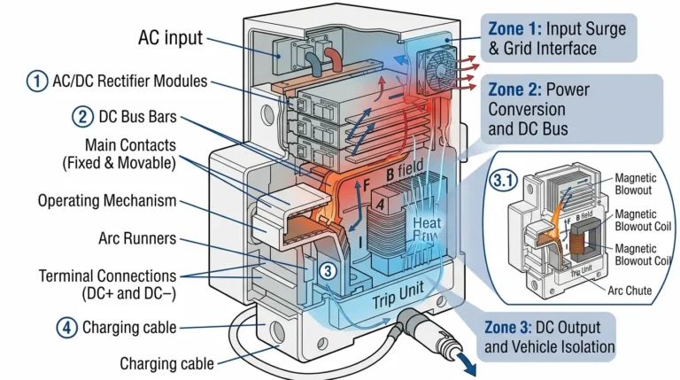
- Interrupción del arco: Requiere cámaras de soplado magnéticas avanzadas
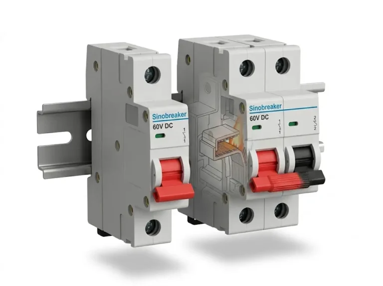
- Montaje: De superficie o atornillado; demasiado grande para carril DIN
Límites de la aplicación:
- Por debajo de 200 A: Energía solar residencial (hasta ~10 kW de inversor a 48 V)
- A 200A: Solar residencial grande (9,6 kW a 48 V), molinete marino
- Más de 200 A: Energía solar comercial, sistemas de baterías industriales, carga rápida de vehículos eléctricos
Consideraciones de ingeniería:
- Corriente nominal de cortocircuito (SCCR): Debe soportar fallos de 5.000-10.000 A
- Tensión nominal: Típicamente 32V, 80V, 125V, o 150V DC máximo
- Reducción de temperatura: Reducción significativa de la capacidad por encima de 40 °C ambiente
- Pérdidas en los conductores: Caída de 0,5-1,0 V a plena carga de 200 A si las conexiones son imperfectas.
El comportamiento de disparo de un disyuntor de CC de 200 A sigue curvas precisas de tiempo-corriente:
Región de disparo térmico (sobrecarga 100-200%):
110% (220A): 60-120 minutos para dispararse
120% (240A): 20-40 minutos para dispararse
135% (270A): 4-8 minutos para el disparo
150% (300A): 1-3 minutos para el disparo
200% (400A): 10-30 segundos para el disparo
Región de disparo magnético (sobrecarga >200%):
300% (600A): 2-5 segundos
500% (1000A): 0,5-2 segundos
1000% (2000A): 0,1-0,5 segundos (cortocircuito)
Por qué importan estas curvas:
La región térmica protege contra sobrecargas sostenidas en las que la carga excede la capacidad pero no ha fallado catastróficamente. Ejemplo: Un inversor de 160 A que consume 220 A de forma continua durante varios minutos debido a cargas pesadas.
La región magnética proporciona una protección rápida contra cortocircuitos en los que la corriente de fallo podría superar los 2000 A en milisegundos, lo que podría provocar un arco eléctrico o la fusión del conductor.
Definición: Corriente máxima que el disyuntor puede interrumpir con seguridad sin daños ni incendio.
Valores típicos de los disyuntores de CC de 200 A:
- Servicio estándar: 5.000 AIC (5kA)
- Carga media: 10.000 AIC (10kA)
- Trabajo pesado: 25.000 AIC (25kA)
- Industrial: 50.000+ AIC (50kA+)
Cómo calcular el AIC requerido:
La corriente de fallo disponible depende de la capacidad y la resistencia interna del banco de baterías:
Corriente de fallo (A) = Tensión de la batería (V) / Resistencia total del circuito (Ω)Ejemplo: Banco de baterías de 48V, 200Ah de litio Resistencia interna de la batería: ~0,010Ω Resistencia del cable (5 pies de 2/0 AWG): 0,00006Ω por pie × 5 × 2 = 0,0006Ω Resistencia de la conexión: 0,001Ω (típico) Resistencia total: 0.010 + 0.0006 + 0.001 = 0.0116Ω
Corriente de defecto = 48V / 0,0116Ω = 4,138A
Interruptor requerido: 5.000 AIC mínimo (seleccione 10.000 AIC por margen de seguridad)
Importante: Las baterías de litio tienen una resistencia interna extremadamente baja y pueden suministrar corrientes de fallo masivas. Las baterías AGM/de plomo-ácido inundadas tienen una mayor resistencia interna (~0,050Ω), lo que limita la corriente de fallo a ~1.000 A.
Tensiones nominales de CC comunes para disyuntores de CC de 200 amperios:
| Tensión nominal | Aplicaciones típicas | Distancia entre arcos |
|---|---|---|
| 32 V CC | 12V/24V automoción, náutica | 1-2 mm |
| 80 V CC | 48V solar residencial | 3-4 mm |
| 125 V CC | Sistemas de baterías de 120 V, telecomunicaciones | 5-6 mm |
| 150 V CC | Cadenas solares comerciales | 6-8 mm |
| 600 V CC | Energía solar fotovoltaica | 15-20 mm |
Por qué es importante la tensión en los interruptores de CC:
A diferencia de la CA, en la que el arco se autoextingue al paso por cero (120 veces por segundo a 60 Hz), los arcos de CC se mantienen indefinidamente. Se requiere una tensión más alta:
- Mayor distancia entre contactos
- Bobinas magnéticas de soplado para estirar el arco
- Canaletas de arco para dividir el arco en secciones más pequeñas
- Mayor presión del muelle para separar los contactos rápidamente
Norma de seguridad crítica: No utilice nunca un disyuntor por debajo de la tensión máxima del sistema, incluidas las tensiones de carga. Un sistema de 48 V con carga flotante de 58,4 V requiere un disyuntor de 80 V CC como mínimo, no de 48 V.
Los disyuntores de CC de 200 amperios generan un calor interno significativo a través de las pérdidas de I²R. La temperatura ambiente afecta directamente a la capacidad:
Tabla de desclasificación (disyuntor termomagnético típico):
| Temperatura ambiente | Capacidad de corriente nominal |
|---|---|
| -20°C (-4°F) | 105% (210A) |
| 0°C (32°F) | 102% (204A) |
| 25°C (77°F) | 100% (200A) - Clasificación estándar |
| 40°C | 95% (190A) |
| 50°C (122°F) | 90% (180A) |
| 60°C (140°F) | 85% (170A) |
| 70°C (158°F) | 80% (160A) |
Ejemplo práctico:
Inversor solar en el ático de Arizona:
- Potencia nominal del inversor: 9,6 kW a 48 V = 200 A
- Temperatura del ático: 55°C
- Reducción de potencia del disyuntor: ~88%
- Capacidad efectiva: 200A × 0,88 = 176A
- ResultadoDisyuntor de 200A: se dispara de forma molesta; necesita un disyuntor de 250A
Estrategias de solución:
1. Mejorar la ventilación (reducir la temperatura ambiente)
2. Monte el disyuntor en el lugar más fresco
3. Aumentar el tamaño del disyuntor a 250 A para compensar
4. Utilizar martillo hidráulico-magnético (sin reducción térmica)

NEC Tabla 310.16 (75°C nominal cable, cobre, 30°C ambiente):
| Tamaño del cable | Ampacidad | ¿Adecuado para 200A? | Uso típico |
|---|---|---|---|
| 3/0 AWG | 200A | Sí (exactamente iguales) | Tamaño mínimo |
| 4/0 AWG | 230A | Sí (preferido) | Instalación estándar |
| 250 kcmil | 255A | Sí (margen 15%) | Entornos calientes |
| 300 kcmil | 285A | Sí (margen 42%) | Recorridos largos, reducción de potencia |
| 350 kcmil | 310A | Sí (margen 55%) | Preparado para el futuro |
Consideraciones críticas:
1. 125% Regla para cargas continuas (NEC 690.8):
“`
Si el inversor funciona más de 3 horas seguidas:
Ampacidad requerida del cable = 200A × 1,25 = 250A
Seleccione: 250 kcmil mínimo
“`
2. Reducción de la potencia de los conductos:
“`
4-6 conductores portadores de corriente: Capacidad 80%
7-9 conductores: Capacidad 70%
Ejemplo: 4/0 AWG (230 A nominales) × 0,80 = 184 A reducidos
Resultado: Insuficiente para un disyuntor de 200 A; aumentar a 250 kcmil
“`
3. Reducción de temperatura:
“`
40°C ambiente: 4/0 AWG × 0,91 = 209A
50°C ambiente: 4/0 AWG × 0,82 = 189A (insuficiente)
“`
Los disyuntores de CC de 200 amperios requieren una terminación especializada:
Método 1: Terminación con terminal de compresión (preferido)
- Utilizar crimpadora hidráulica (matriz estándar)
- Terminales de compresión de cobre de 200 A continuos
- Aplique compuesto antioxidante antes de crimpar
- Conexión termorretráctil para proteger de la humedad
- Par de apriete según especificación del fabricante: 200-300 in-lbs típico
Método 2: Lengüeta mecánica (tornillo prisionero)
- Diseño de dos tornillos mínimo para 200A
- Requiere cable trenzado (no sólido)
- Aplicar compuesto antioxidante
- Apriete ambos tornillos uniformemente
- Es necesario un reapriete periódico (anual)
Método 3: Conexión de bus atornillada
- Atornillado directo a la barra colectora
- Múltiples pernos para la distribución de corriente
- Las arandelas Belleville evitan que se aflojen
- Especificación de par: 25-35 ft-lbs típico
Objetivo de resistencia a la conexión:
- Máximo: 50 microohmios (0,00005Ω)
- A 200A: Pérdida de potencia = I²R = (200)² × 0,00005 = 2W por conexión
- Aumento de temperatura: ~5°C aceptable
- Mala conexión (500 microohmios): Pérdida de 20 W, aumento de 50 °C - FALLO
Comprobación de la calidad de la conexión:
1. Inspección visual (ausencia de huecos, corrosión)
2. Verificación del par con llave calibrada
3. Medición de la caída de tensión (debe ser <0,1 V a plena carga) 4. Imágenes térmicas (la conexión no debe superar la temperatura corporal del disyuntor)

Aplicación típica 200AInversor de 9,6 kW a 48 V nominales
Parámetros clave de diseño:
1. Corriente de sobretensión del inversor:
- Estado estacionario: 9600W ÷ 48V = 200A
- Sobretensión de arranque: 1,5-2,0× nominal = 300-400 A durante 1-5 segundos
- El disyuntor NO debe dispararse al arrancar
- Solución: Seleccione un disyuntor con capacidad instantánea de 300 A
2. Variación del voltaje de la batería:
“`
Rango de tensión real del sistema de 48 V:
- Carga completa: 58,4V (LiFePO4)
- Nominal: 51.2V
- Corte por baja tensión: 44 V
Corriente del inversor a baja tensión:
9600W ÷ 44V = 218A (¡9% por encima del valor nominal!)
Tamaño del disyuntor: Debe acomodar 218A continuamente
Seleccione un disyuntor de 250 A O una salida de inversor con límite de corriente
“`
3. Cableado:
- Mantenga los cables principales de CC a menos de 3 m para minimizar la caída de tensión - Cada caída de tensión de 1% desperdicia 96 W a 9,6 kW - Utilice el mismo calibre para el positivo y el negativo - Tienda los cables lejos de fuentes de calor
4. Requisitos de conexión a tierra (NEC 690.41):
- La mayoría de los sistemas requieren conexión a tierra
- El sistema de baterías puede estar conectado a tierra o ser flotante
- Si está conectado a tierra: Conecte el negativo a tierra sólo en UN punto
- Protección contra fallos a tierra necesaria para algunos sistemas
Aplicación típica 200A: Molinete de ancla eléctrico de 12 V (2400 W)
Desafíos marinos únicos:
1. Corriente alta intermitente:
- El molinete tira de la cadena: 150-250 A durante 30-120 segundos
- El disparo térmico debe tolerar sobretensiones sin disparos molestos
- Seleccione un disyuntor con alta capacidad instantánea (400A+)
2. Caída de tensión Crítica:
“`
Sensibilidad del motor del molinete:
A 10V (en lugar de 12V): Reducción de par 30%
Caída máxima aceptable: 1,0V (8,3%)
Ejemplo: cable de 6 metros a 200 A
Resistencia requerida: 1,0V ÷ 200A = 0,005Ω total.
Resistencia del cable: 0,005Ω ÷ (2 × 20 pies) = 0,000125 Ω/pie.
Requisitos del cable: 2/0 AWG mínimo (0,0001 Ω/pie)
Mejor: 4/0 AWG (0,0000806 Ω/pie) = caída de 0,64 V
“`
3. Protección contra la corrosión:
- Alambre de cobre estañado obligatorio
- Terminales de acero inoxidable o chapados en oro
- Revestimiento conformado en el interior del martillo
- Caja del disyuntor con clasificación IP67
- Inspección y limpieza anuales
4. Protección de encendido (ABYC E-11.17):
- Molinete normalmente en espacio no peligroso
- Si está cerca de un motor de gasolina: se requiere un disyuntor con protección de encendido
- La carcasa sellada del disyuntor evita el encendido por chispa
Aplicación: Seccionador de banco de baterías de litio 200Ah+
Funciones críticas de seguridad:
1. Parada de emergencia:
- Debe ser accesible en <5 segundos - Maneta roja o actuador tipo paleta - Etiquetado “DESCONEXIÓN BATERÍA PRINCIPAL” - Situado a la vista de la batería
2. Mantenimiento Aislamiento:
- Verificación de tensión cero tras la apertura
- Capacidad de bloqueo/etiquetado (cerradura de candado)
- Indicación visible de abierto/cerrado
3. Integración de BMS:
- El sistema de gestión de la batería puede ordenar la desconexión
- Algunos disyuntores de 200A ofrecen bobina de disparo en derivación (24V/48V CC)
- El disparo en derivación abre el disyuntor de forma remota en caso de sobretemperatura o sobretensión.
4. Bancos de baterías en paralelo:
“`
Dos baterías de 100Ah en paralelo = 200Ah en total
Cada batería tiene una capacidad de 100 A continuos y 200 A de sobretensión.
Combinado: 200 A continuos, 400 A sobretensión
Dimensionamiento del interruptor:
- Interruptor principal: 200 A (partidos combinados continuos)
- Interruptores de batería individual: 125A (corresponde a una sola batería × 1,25)
“`
Termomagnético (estándar)
Principio de funcionamiento:
- La cinta bimetálica se calienta con la corriente
- Bobina magnética para disparo rápido por cortocircuito
- Protección combinada temporizada e instantánea
Ventajas:
- Menor coste ($80-150 típico)
- Ampliamente disponible
- Funcionamiento sencillo
Desventajas:
- Sensible a la temperatura ambiente (requiere reducción de potencia)
- El punto de disparo se desplaza con la edad
- No apto para aplicaciones de ciclo alto
Lo mejor para: Inversores solares estándar, instalaciones fijas, temperaturas ambiente moderadas
Hidráulico-magnético (Premium)
Principio de funcionamiento:
- El amortiguador de fluido hidráulico proporciona retardo
- Núcleo magnético para disparo instantáneo
- Diseño con compensación de temperatura
Ventajas:
- Sin reducción térmica (mantiene 200 A a 70 °C)
- Punto de disparo preciso (±5% frente a ±20% para térmico)
- Larga vida útil (más de 50.000 operaciones)
- Inmune a la temperatura ambiente
Desventajas:
- Mayor coste ($200-400 típico)
- Disponibilidad limitada
- Requiere una orientación de montaje específica (basada en fluidos)
Lo mejor para: Aplicaciones marinas, entornos calurosos (salas de máquinas), cargas cíclicas frecuentes (molinetes, propulsores).
Cuadro comparativo:
| Característica | Termomagnético | Hidráulico-magnético |
|---|---|---|
| Coste | $80-150 | $200-400 |
| Reducción de la temperatura | Sí (15-20% a 60°C) | Ninguno |
| Precisión del viaje | ±20% | ±5% |
| Ciclo de vida | 5,000-10,000 | 50,000+ |
| Mantenimiento | Raro | Ninguno |
| Temperatura ambiente | -20°C a 60°C | -40°C a 80°C |
| Mejor uso | Inversor solar fijo | Molinete/timón marino |
Principio de funcionamiento:
- Sensor de corriente (shunt o efecto Hall)
- Lógica de disparo por microprocesador
- Mecanismo de disparo por solenoide electrónico
Ventajas:
- Curvas de disparo programables
- Capacidad de supervisión remota
- Puntos de disparo precisos (±2%)
- Múltiples modos de protección (sobrecorriente, subtensión, polaridad inversa)
- Registro de datos
Desventajas:
- Requiere alimentación auxiliar (consumo parásito 1-5W)
- Más complejo (más modos de fallo)
- Mayor coste ($300-600)
- Puede fallar en entornos difíciles
Lo mejor para: Sistemas industriales, requisitos de supervisión a distancia, sistemas con integración BMS

Requisitos de montaje:
1. Orientación del interruptor:
- Termomagnético: Es preferible el montaje vertical (el calor asciende de forma natural)
- Montaje horizontal: Derate 5-10%
- Al revés: No recomendado (el calor afecta al mecanismo de disparo)
- Hidráulico-magnético: Debe seguir la orientación del fabricante (a base de fluidos)
2. Espacios libres:
- Parte superior: 3 pulgadas como mínimo (disipación del calor)
- Laterales: 2 pulgadas (circulación de aire)
- Espacio de trabajo: 36 pulgadas de fondo × 30 pulgadas de ancho (NEC 110.26)
3. Apoyo estructural:
- Peso del rompedor: 3-5 lbs típico
- Peso del conductor: 1-2 libras por pie para 4/0 AWG
- Peso total del sistema: 10-20 libras
- Se monta en un elemento estructural, no en paneles de yeso
4. Aislamiento de vibraciones (Marina/RV):
- Utilice aislantes de goma o almohadillas antivibraciones
- Evita que la conexión se afloje por las vibraciones
- Comprobación trimestral del par de apriete en entornos con muchas vibraciones
Especificaciones de par:
Un par de apriete adecuado evita:
- Conexiones sueltas → alta resistencia → calentamiento → incendio.
- Par de apriete excesivo → roscas dañadas → aflojamiento por el paso del tiempo.
| Tamaño del terminal | Especificación de par |
|---|---|
| Lengüeta 200A (2/0-4/0 AWG) | 250-350 in-lbs (21-29 ft-lbs) |
| Conexión de barras | 300-400 in-lbs (25-33 ft-lbs) |
| Terminal de tierra | 150-200 in-lbs (12-17 ft-lbs) |
Procedimiento de par:
1. Limpiar las superficies de los terminales (almohadilla ScotchBrite)
2. Aplicar compuesto antioxidante
3. Inserte el conductor completamente en el terminal
4. Par en etapas: 50% → 75% → 100%
5. Verificar que no hay movimiento del conductor
6. Marcar con pintura de sellado de par
7. Reapriete después de 24 horas (asentamiento inicial)
Cable Dressing:
Mejores prácticas:
- Radio de curvatura mínimo: 10× diámetro del cable.
  (4/0 AWG = 0,528" de diámetro → 5,28" de curvatura mínima).
- Apoye los cables cada 18-24 pulgadas
- Evite las curvas cerradas (crean puntos de tensión)
- Coloque el positivo y el negativo juntos (minimiza la inductancia)
- Manténgalos alejados de fuentes de calor (tubos de escape, motores)
- Utilice prensaestopas para las penetraciones en la caja
Pruebas previas a la energización:
1. Lista de comprobación de la inspección visual:
- [ ] Todas las terminaciones con el par de apriete especificado
- [ ] No hay conductores expuestos
- [ ] Se ha instalado un calibre de cable adecuado
- [ ] Polaridad marcada correctamente (+/-)
- [ ] Interruptor nominal para la tensión del sistema
- [ ] Interruptor etiquetado con el nombre del circuito y el amperaje
- [ ] Espacios libres mantenidos
- [ ] Montaje seguro
2. Prueba de resistencia del aislamiento (Megóhmetro):
“`
Procedimiento de prueba:
- Desconecte la carga y la fuente
- Ajuste el megóhmetro a una tensión de prueba de 500 V CC
- Mida el positivo a tierra: Debe ser >1 MΩ
- Mida el negativo a tierra: Debe ser >1 MΩ
- Mida de positivo a negativo: Debe ser >1 MΩ (con la carga desconectada).
Si <1 MΩ: Indica rotura del aislamiento o humedad “`
3. Prueba de continuidad:
“`
Con el multímetro en modo resistencia:
- Interruptor ABIERTO: Debe indicar resistencia infinita (OL)
- Interruptor CERRADO: Debe indicar <0,001Ω (esencialmente 0Ω).
Alta resistencia cuando está cerrado: Contacto interno deficiente, sustituya el disyuntor
“`
4. Prueba de caída de tensión:
“`
Con el disyuntor cerrado y la carga energizada a 80% (160A):
- Mida la tensión en la entrada del disyuntor
- Mida la tensión en la salida del interruptor
- Calcula la caída: Debe ser <0.2V
Si >0,5V: Indica conexiones sueltas o disyuntor subdimensionado.
“`
Pruebas posteriores a la energización:
1. Imágenes térmicas (Después de 1 hora con una carga de 80%):
- Temperatura del cuerpo del disyuntor: <60°C por encima de la temperatura ambiente aceptable - Conexiones de terminales: Deben coincidir con la temperatura del cuerpo del interruptor (±5°C) - Los puntos calientes indican problemas: Retorque las conexiones
2. Prueba de viaje (Si es factible):
“`
Precaución: Puede dañar la carga si se realiza incorrectamente
Procedimiento:
1. Aumentar gradualmente la carga hasta 135% (270A)
2. El disyuntor debe dispararse en 4-8 minutos
3. Si se dispara demasiado rápido: Interruptor demasiado pequeño o defectuoso
4. Si no se dispara: Interruptor sobredimensionado o defectuoso
Nota: La mayoría de las instalaciones omiten esta prueba; confían en las pruebas del fabricante.
“`
Trimestralmente (Marina/RV) o Semestralmente (Instalación fija):
- Inspección visual de la corrosión
- Comprobación del par de apriete de todas las conexiones (pueden aflojarse con el tiempo)
- Limpiar las superficies exteriores
- Compruebe que el disyuntor se reinicia sin problemas
- Compruebe si hay calor u olores extraños
Anualmente:
- Imágenes térmicas bajo carga
- Prueba de resistencia del aislamiento
- Medición de la caída de tensión
- Limpiar las superficies de los terminales y volver a aplicar el compuesto antioxidante.
- Documentar los resultados
Problema 1: El disyuntor se dispara con una carga de 70-80%
Posibles causas:
1. Temperatura ambiente demasiado alta (reducción térmica)
2. Mala ventilación alrededor del disyuntor
3. El interruptor se acerca al final de su vida útil (el punto de disparo desciende)
4. Conexiones sueltas que generan calor adicional
Pasos de diagnóstico:
1. Mida la corriente real con una pinza amperimétrica de CC
2. Mida la temperatura ambiente cerca del disyuntor
3. Calcular la capacidad reducida
4. Compruebe la caída de tensión en el interruptor (>0,5 V indica un problema).
5. 5. Conexiones de imagen térmica
Soluciones:
- Mejorar la ventilación o reubicar el disyuntor
- Ampliación a disyuntor de 250 A
- Sustituir el disyuntor antiguo
- Retorque las conexiones
Problema 2: El disyuntor no se dispara durante una sobrecarga evidente
Posibles causas:
1. Interruptor sobredimensionado para la carga real
2. Fallo del interruptor (contactos soldados)
3. Medición incorrecta de la corriente
Pasos de diagnóstico:
1. Verificar la corriente real con un medidor calibrado
2. Pruebe el disyuntor manualmente con el botón de prueba (si está equipado)
3. Mida la resistencia a través del interruptor cuando esté "abierto" (debe ser infinita).
4. Si <100Ω cuando está abierto: Contactos soldados, se requiere reemplazo inmediato
Soluciones:
- Sustituir el disyuntor (contactos soldados = peligro de incendio)
- Verifique el tamaño adecuado del disyuntor para el circuito
Problema 3: Caída de tensión excesiva a través del disyuntor
Normal: 0,1-0,3 V a corriente nominal
Excesivo: >0,5 V a corriente nominal
Causas:
- Terminales corroídos
- Conexiones sueltas
- Degradación interna del disyuntor
Soluciones:
1. Apagar el sistema
2. Desconecte los cables
3. 3. Limpie los terminales con ScotchBrite
4. Limpie los terminales del disyuntor con limpiador de contactos eléctricos
5. 5. Aplique compuesto antioxidante nuevo
6. 6. Vuelva a conectar y apriete correctamente
7. Vuelva a comprobar la caída de tensión
8. Si sigue siendo excesiva: Sustituya el disyuntor
Blue Sea Systems Serie 7700 - 200A Montaje en superficie
- Precio: $120-150
- Características: Termomagnético, IP67, protegido contra ignición
- Clasificación AIC: 10,000A
- Lo mejor para: Molinete marino, circuitos de propulsión
- Garantía2 años
Carling Technologies Serie E - 200A Hidráulico-Magnético
- Precio: $280-350
- Características: Sin reducción térmica, vida útil de 50.000 ciclos
- Clasificación AIC: 10,000A
- Lo mejor para: Entornos calurosos, ciclismo frecuente
- Garantía: 3 años
Bussman Serie 185 - 200A
- Precio: $80-110
- Características: Termomagnético, montaje en superficie
- Clasificación AIC: 5,000A
- Lo mejor para: Circuitos de inversores solares, instalaciones fijas
- Garantía: 1 año
Megafusible Victron Energy 200A (Alternativa)
- Precio: $15-25 por fusible + $60 soporte
- Nota: Fusible, no disyuntor (debe sustituirse después del disparo)
- Lo mejor para: Construcciones económicas, protección de seguridad
ABB Tmax T1 200A CC
- Precio: $400-600
- Características: Unidad de disparo electrónica, curvas ajustables, supervisión remota
- Clasificación AIC: 25,000A
- Lo mejor para: Sistemas de baterías industriales, supervisión a distancia
- Garantía: 3 años
1. ¿Puedo utilizar un disyuntor de CA de 200 A para aplicaciones de CC?
No, absolutamente nunca. Los disyuntores de CA están diseñados para corriente alterna de 60 Hz, que extingue los arcos de forma natural 120 veces por segundo en el punto de cruce por cero. La CC no tiene cruce por cero, por lo que los arcos se mantienen indefinidamente. Un disyuntor de CA de 200 A en CC fallará catastróficamente, pudiendo provocar un arco eléctrico, un incendio o una explosión. Utilice siempre disyuntores específicamente clasificados para voltaje de CC (por ejemplo, se requiere la marca “80V CC” o “125V CC”).
2. ¿Cómo puedo calcular si un disyuntor de 200 A es suficiente para mi inversor solar?
Divida la potencia del inversor por la tensión mínima de la batería: Corriente = Vatios ÷ Tensión. Ejemplo: inversor de 10 kW en un sistema de 48 V nominales con corte de baja tensión de 44 V: 10.000 W ÷ 44 V = 227 A. Aplique la regla NEC 125% para cargas continuas: 227A × 1,25 = 284A necesarios. Resultado: el disyuntor de 200 A es insuficiente; necesita 300 A o limitar la corriente de salida del inversor a 8 kW como máximo.
3. ¿Por qué se dispara mi disyuntor de 200 A cuando mi inversor sólo consume 180 A?
Probable reducción de la temperatura ambiente. Un disyuntor termomagnético de 200 A a 25 °C disminuye su capacidad a ~180 A a 50 °C y a ~170 A a 55 °C. Compruebe la temperatura de la ubicación del interruptor. Soluciones: mejorar la ventilación, reubicar el disyuntor en un lugar más fresco, cambiar a un disyuntor hidráulico-magnético (sin reducción térmica) o aumentar el tamaño a un disyuntor de 250 A.
4. ¿Qué calibre de cable necesito para un disyuntor de CC de 200 A?
Mínimo 3/0 AWG cobre (200A ampacidad), pero 4/0 AWG (230A) preferido para 15% margen de seguridad. Para cargas continuas >3 horas, NEC exige una ampacidad de 125%: 200A × 1,25 = 250A, lo que requiere un cable de 250 kcmil como mínimo. Tenga en cuenta también la reducción de potencia por agrupamiento (0,8× para 4-6 cables en conducto) y la reducción de potencia por temperatura (ambiente >40°C). Dimensione siempre el cable para protegerlo contra el sobrecalentamiento, independientemente del valor nominal del disyuntor.
5. ¿Cuál es la diferencia entre un disyuntor de 200 A y un fusible de 200 A?
Los disyuntores son rearmables; los fusibles deben sustituirse después de su funcionamiento. Los disyuntores tienen características de retardo (disparo térmico); los fusibles suelen ser más rápidos. Los disyuntores cuestan más al principio ($80-400) pero ahorran dinero a largo plazo. Los fusibles son más precisos (±10% frente a ±20% de los disyuntores térmicos) y tienen mayor capacidad de interrupción (100kA+ posible). Para circuitos de seguridad críticos, utilice fusibles como protección de reserva detrás de los disyuntores.
6. ¿Puedo poner en paralelo dos disyuntores de 100 A para obtener una capacidad de 200 A?
No, nunca ponga en paralelo disyuntores o fusibles. La corriente no se dividirá uniformemente debido a pequeñas diferencias de resistencia: un disyuntor soportará más carga y se disparará primero mientras el otro permanece cerrado. Esto anula el propósito de la protección contra sobrecorriente. En su lugar, utilice un único disyuntor para toda la corriente de carga. La conexión en paralelo sólo es aceptable para los conductores, no para los dispositivos de protección.
7. ¿Qué tan cerca de 200 A puedo cargar continuamente un disyuntor de 200 A?
Máximo 80% para trabajo continuo (>3 horas): 160A. NEC define la carga continua como el funcionamiento durante tres o más horas. Para cargas intermitentes (<1 hora), es aceptable un funcionamiento breve a 100% (200A). El funcionamiento continuo por encima de 80% provoca un calentamiento excesivo, reduce la vida útil del disyuntor y puede causar disparos molestos, especialmente en entornos cálidos. Diseñado para una carga continua máxima de 160 A o para un disyuntor de 250 A.
Los disyuntores de CC de 200 amperios representan un punto de inflexión crítico en el que los componentes de grado residencial se encuentran con los requisitos de grado industrial. Una selección, instalación y mantenimiento adecuados garantizan una protección fiable durante años.
Lista de comprobación de ingeniería:
Fase de selección:
- [ ] Calcular la corriente de carga real, incluidas las condiciones de baja tensión
- [ ] Aplicar la regla 125% para cargas continuas (>3 horas)
- [ ] Determinar la capacidad de interrupción necesaria (AIC) en función del banco de baterías
- [ ] Seleccione la tensión nominal ≥ máxima del sistema (incluida la tensión de carga)
- [ ] Considerar la reducción de la temperatura ambiente (cambiar a hidráulico-magnético si >50°C)
- [ ] Evaluar la compatibilidad de la curva de disparo con las características de la carga
Fase de instalación:
- [ ] Tamaño de los conductores para 125% de la capacidad mínima del disyuntor
- [ ] Utilizar terminales de compresión con crimpadora hidráulica
- [ ] Aplique un compuesto antioxidante a todas las conexiones
- [ ] Apriete según las especificaciones del fabricante (250-350 in-lbs típico)
- [ ] Mantener las holguras adecuadas (3″ arriba, 2″ lados).
- [ ] Etiquetar el disyuntor con el nombre y la potencia del circuito
Fase de puesta en servicio:
- [ ] Prueba de resistencia de aislamiento >1 MΩ
- [ ] Prueba de continuidad <0,001Ω cuando está cerrado - [ ] Prueba de caída de tensión <0,2V con carga 80% - [ ] Imágenes térmicas después de 1 hora a plena carga - [ ] Documentar todos los resultados de las pruebas. Fase de mantenimiento:
- [ ] Comprobación trimestral del par de apriete e inspección visual
- [ ] Imágenes térmicas anuales bajo carga
- [ ] Sustituya inmediatamente cualquier elemento corroído
- [ ] Prever la sustitución del disyuntor cada 10-15 años (térmico-magnético)
Calidad frente a coste:
Para aplicaciones críticas (protección de la vida marina, energía solar conectada a la red), invierta en disyuntores hidráulico-magnéticos de gama alta ($250-350). Para la protección estándar de inversores solares en lugares con clima controlado, basta con disyuntores termomagnéticos de gama media ($80-150).
La diferencia de coste es insignificante comparada con la inversión en el sistema: un disyuntor $300 que protege un inversor $15.000 y un banco de baterías $30.000 es una sabia ingeniería.