Adresse
304 Nord Kardinal
St. Dorchester Center, MA 02124
Arbeitszeiten
Montag bis Freitag: 7AM - 7PM
Am Wochenende: 10AM - 5PM
Adresse
304 Nord Kardinal
St. Dorchester Center, MA 02124
Arbeitszeiten
Montag bis Freitag: 7AM - 7PM
Am Wochenende: 10AM - 5PM

Before you compare models, it helps to understand why a true 1500V DC breaker is different from a standard low-voltage breaker.
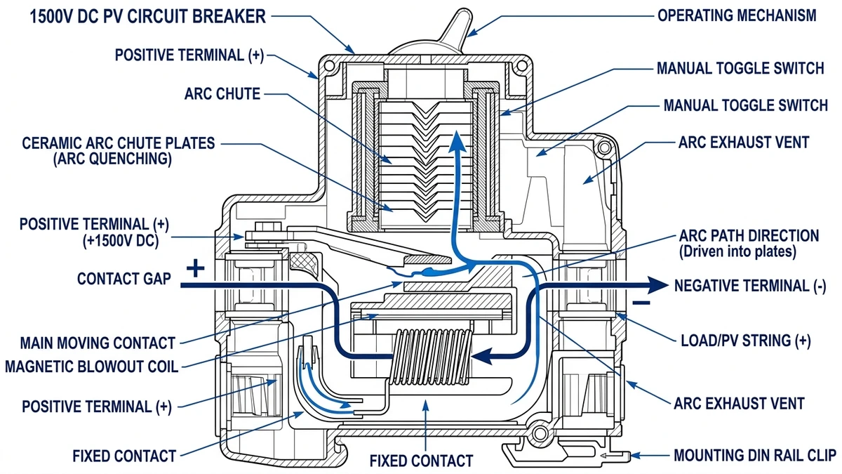
A 1500V DC circuit breaker is a protective switching device engineered to interrupt fault currents in photovoltaic string and array circuits operating at up to 1500 volts direct current. Unlike standard AC breakers, it must extinguish a sustained DC arc with no natural current zero crossing, requiring specialized contact geometry, arc chute design, and magnetic blowout systems.
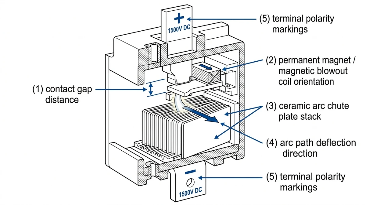
AC breakers benefit from current naturally crossing zero 100–120 times per second, which helps extinguish the arc. DC systems offer no such advantage. In a 1500V DC string circuit, a fault arc can sustain unless the breaker actively drives arc voltage above system voltage. That requires arc elongation through magnetic blowout coils—typically generating 80–200 mT field strength—combined with ceramic arc chute plates that cool and segment the arc column.
In a 120 MW ground-mount installation in Inner Mongolia (2023), engineers documented that undersized DC breakers rated only to 1000V failed arc interruption tests at 1500V string voltage, with arc energy escaping the enclosure in 3 of 12 test units. Properly rated 1500V DC MCBs from the replacement batch cleared the same fault conditions within 8–15 ms.
IEC 60947-2 governs low-voltage circuit breakers for DC applications and defines the minimum performance thresholds a device must meet to carry a 1500V DC rating:
The contact gap is a direct physical constraint. Interrupting 1500V DC requires roughly 2× the contact separation needed for a 750V DC rating, which is why a single-pole 1000V AC breaker cannot be substituted.
For solar string protection specifically, the DC MCCB series designed for 1500V PV systems may also incorporate reverse current blocking, since PV strings can experience reverse polarity under partial shading or bypass diode failure conditions.
Once the breaker itself is clear, the next buying decision is matching each device to the fault level at its position in the PV system.
In a 1500V DC utility-scale PV system, circuit breaker placement follows a three-tier hierarchy—string level, combiner level, and inverter DC input level. Each tier carries distinct fault current exposure, voltage stress, and isolation requirements.
IEC 62548-1 governs PV array design requirements and establishes that string circuits in 1500V systems typically sustain 1.25 × Isc continuously, with prospective fault currents at the combiner bus reaching 8–20 kA depending on string count. That range separates MCB territory from MCCB territory. A DC-MCB fits individual string protection at lower fault energy, while a DC MCCB is the appropriate choice at combiner output and inverter input where fault current aggregates.
In a 120 MW ground-mount installation in Inner Mongolia (2023), engineers found that mismatched breaker tiers—specifically, MCBs installed at combiner output positions—caused nuisance tripping during cloud-edge irradiance spikes because the devices lacked the Ics rating to hold under transient overcurrent without actuating.
| Protection Tier | Location | Typical Voltage | Typischer Fehlerstrom | Recommended Device |
|---|---|---|---|---|
| Tier 1 — String | String junction to combiner input | Bis zu 1500 VDC | 1–3 kA | 1500V DC MCB or gPV fuse |
| Tier 2 — Combiner | Combiner box output to DC trunk cable | Bis zu 1500 VDC | 8–20 kA | DC MCCB (Icu ≥ 20 kA) |
| Tier 3 — Inverter DC Input | DC busbar at inverter terminals | Bis zu 1500 VDC | 20–50 kA | DC MCCB + SPD coordination |
Surge protection at Tier 3 is non-negotiable. The IEC 61643-11 standard governs SPD selection for DC PV systems, and inverter-side SPDs must be coordinated with upstream MCCB breaking capacity to prevent SPD failure from propagating a busbar fault.
For combiner-level protection hardware, PV-Kombinatorkästen integrate the Tier 1-to-Tier 2 transition in a single enclosure, simplifying both installation and maintenance isolation.
[Expert Insight]
– Put the available fault current calculation on the single-line diagram for each tier; it prevents MCB/MCCB substitution during procurement.
– If a combiner has future expansion space, size the breaker to the full populated-string fault level, not the day-one installed string count.
– Check whether the inverter maker requires a minimum upstream breaker Ics or only Icu; the difference affects service life after repeated faults.
With the system map in place, you can evaluate breakers by the ratings that actually decide field suitability.
Selecting a 1500V DC circuit breaker for utility-scale PV comes down to five rated parameters defined under IEC 60947-2.
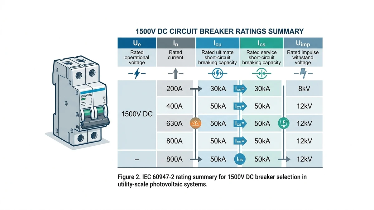
| Parameter | Symbol | Typical Range (1500V PV) | What Undersizing Causes |
|---|---|---|---|
| Nennspannung | Ue | 1000-1500 VDC | Arc not extinguished; breaker destroyed |
| Rated Current | Unter | 16–125 A | Thermal overload, nuisance tripping |
| Ultimate Breaking Capacity | Icu | 20–65 kA | Catastrophic failure under fault |
| Service Breaking Capacity | Ics | 15–50 kA (≥ 75% Icu per IEC 60947-2) | Breaker non-resettable after fault |
| Rated Impulse Withstand Voltage | Uimp | 8–12 kV | Dielectric failure from lightning transients |
Icu is the maximum fault current a breaker can interrupt once, after which it may need replacement. Ics is the breaking capacity after which the device remains serviceable and resettable. For a PV plant where string-level faults can recur seasonally, specifying only to Icu can leave you with a single-use protection device. Always confirm the Ics/Icu ratio in the manufacturer’s datasheet before finalizing a DC MCCB selection.
Uimp is also frequently overlooked in solar procurement. Utility-scale sites in high-keraunic zones regularly see transient overvoltages above 6 kV, so 8 kV is a practical minimum threshold on a 1500V bus. Pairing breakers with a properly rated surge protection device closes the gap that Uimp alone cannot cover.
After ratings are decoded, sizing becomes a straightforward calculation tied to current, voltage, and available fault energy at the installation point.
Sizing a 1500V DC circuit breaker for a utility-scale PV system comes down to four parameters: short-circuit current, voltage rating, breaking capacity, and continuous current rating.
Start with the module datasheet Isc at standard test conditions, then apply the IEC 62548-1 correction factor. The design current for string protection is:
Idesign = 1.25 × Isc,STC × Itemp correction
For a typical 700 W bifacial module with Isc = 18.2 A, this gives approximately 22.75 A per string.
Every breaker in a 1500V string circuit must carry a rated voltage of at least 1500 VDC. Look for IEC 60947-2 or UL 489B certification at the full 1500 VDC rating, not a value derived from an AC figure.
The breaker’s rated ultimate breaking capacity must exceed the prospective short-circuit current at the point of installation. In a 50 MW ground-mount plant in Gansu Province (2023), combiner box busbars measured prospective fault currents of 20–25 kA, and string-level DC MCBs rated below that threshold failed pre-commissioning testing. A minimum Icu of 25 kA at 1500 VDC is a common design floor for utility-scale strings.
The breaker’s rated continuous current (In) must be at least 1.25 × Isc per IEC 62548-1. For the example above, that means selecting a breaker rated at least 25 A continuous. Most DC circuit breakers for 1500V PV service are available in 25 A, 32 A, and 40 A frames, so choose the next standard size up from your calculated minimum.
For a 700 W module string at 1500V: Isc = 18.2 A → design current = 22.75 A → select a 25 A, 1500 VDC breaker with Icu ≥ 25 kA. Cross-check against the gPV fuse coordination curve to confirm selectivity at the combiner level. Also confirm the breaker carries a test certificate at rated DC voltage, not interpolated from AC test data.
A correctly sized breaker on paper can still be wrong in the field, which is why derating is often the difference between stable operation and repeated failures.
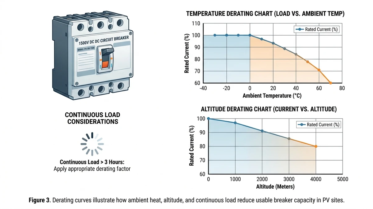
A 1500V DC circuit breaker rated at standard conditions rarely performs identically in service. Ambient temperature, altitude, and continuous load factor can reduce effective performance enough to force a larger frame size or a different installation approach.
Most DC circuit breakers are rated at 40°C. In desert utility sites, combiner box internal temperatures routinely reach 65–75°C during peak irradiance. Continuous current rating may need to be derated by roughly 0.5–1.0% per °C above the reference temperature. For a 63 A breaker operating at 70°C, that translates to a usable current of roughly 47–50 A. In a 120 MW ground-mount project in Xinjiang (2023), engineering teams specified 80 A-rated DC MCCBs to maintain adequate margin at sustained 68°C enclosure temperatures.
At elevations above 2000 m, reduced air density lowers dielectric strength and impairs arc cooling. IEC 60664-1 specifies insulation-coordination corrections above 2000 m. A breaker with a 1500V DC breaking capacity at sea level may require voltage derating to 1200–1350V at 3000 m. For Tibetan Plateau installations operating at 3500–4500 m, this becomes a primary selection constraint.
PV string circuits often run at a high fraction of Isc through much of the day. A string producing 12 A Isc therefore requires a breaker rated at minimum 15 A, and often 20 A when temperature derating is added on top.
[Expert Insight]
– Ask suppliers for published derating curves at your actual enclosure temperature, not just the catalog reference temperature.
– For high-altitude sites, verify whether terminals, clearances, and insulation system are all covered by the altitude correction—not only the breaker body.
– If the combiner box is sun-exposed, use the internal measured temperature as the basis for derating, not ambient weather-station temperature.
If the project is in the U.S. or Canada, compliance rules shift from pure IEC selection toward listing and code acceptance.
For utility-scale PV projects in North America, 1500V DC circuit breaker selection is governed by NEC Article 690 and UL 489B. Understanding how these align—and where they differ—from IEC practice is essential before specifying equipment for U.S. or Canadian sites.
NEC Article 690 requires that all DC overcurrent protective devices in PV systems be listed for DC use at the system’s maximum voltage. For 1500V string architectures, this means breakers must carry a DC voltage rating of at least 1500V and an interrupting rating matching available fault current at the point of installation. Article 690.9 also requires overcurrent devices to protect conductors based on ampacity, not just module Isc.
UL 489B governs supplementary protectors used in PV applications, while IEC 60947-2 covers industrial circuit breakers more broadly. The practical differences matter for procurement:
| Parameter | UL 489B | IEC 60947-2 |
|---|---|---|
| Voltage rating method | Tested at rated DC voltage | Tested per polarity configuration |
| Arc interruption verification | DC-specific test sequences | AC/DC with derating tables |
| Listing requirement for NEC | Mandatory | Not accepted without dual cert |
| Typical breaking capacity | 10 kA at 1500 VDC | Up to 25 kA (device-dependent) |
Many manufacturers now offer DC MCBs and MCCBs carrying both IEC 60947-2 and UL 489B certifications, which simplifies procurement for projects with international supply chains. In a 120 MW ground-mount project in Texas (2024), the EPC contractor specified dual-certified 1500V breakers to satisfy both the AHJ listing requirement under NEC 690 and the IEC-based engineering specifications from the European project developer.
For Canadian projects, confirm with the local AHJ whether UL listing alone is acceptable or whether CSA certification is also required.
For the latest code-adoption and standards context, reviewers can also cross-check current electrical guidance through the NFPA code portal.
Once the shortlist is down to real suppliers, the deciding factor is usually verification depth rather than headline ratings.
A datasheet confirms ratings, but it does not confirm manufacturing consistency, test scope, or support quality. Procurement teams that evaluate vendors on datasheet values alone routinely miss critical quality signals.
In a 120 MW ground-mount project in Inner Mongolia (2024), the engineering team disqualified two shortlisted suppliers after a third-party audit revealed that breaking capacity tests had been conducted at 1000V DC, not the specified 1500V DC—a discrepancy invisible on the product datasheet.
Not all certifications carry equal weight. Verify that IEC 60947-2 or IEC 60898-2 test reports cover the full 1500V DC rated voltage, not a lower test voltage. Request the actual test report, not just the certificate number. Confirm the certifying body is IECEE-recognized, and check that the certificate scope includes DC breaking capacity at the rated interrupting current.
| Evaluation Category | What to Verify | Red Flag |
|---|---|---|
| Test Voltage | Breaking capacity tested at 1500V DC (not 1000V) | Report shows Icu at lower voltage |
| Certification Scope | IECEE CB report covers DC polarity and rated Icu | Certificate only covers AC version |
| Factory Audit | ISO 9001 + production line inspection available | Audit access refused or restricted |
| Arc Chute Material | Ceramic or fiber-reinforced arc chute confirmed | Unspecified or plastic arc chute |
| Rückverfolgbarkeit | Batch-level QC records and lot traceability | No serialization or batch documentation |
| Derating Curves | Published derating data for 50°C+ ambient | No thermal derating curves provided |
| Application Support | Engineer available for string sizing review | Sales-only contact, no technical team |
| Warranty & Spares | Minimum 5-year warranty, spare parts stocked | Warranty under 2 years or parts unavailable |
For surge coordination, also confirm that the vendor’s DC SPD lineup is tested to IEC 61643-31 and compatible with the same busbar architecture.
After the technical checks are complete, the best purchase is the one that meets rating, coordination, and support requirements without adding avoidable procurement risk.
Selecting the right 1500V DC circuit breaker for a utility-scale PV system means more than matching voltage ratings—it means choosing a partner who understands IEC 60947-2 breaking capacity requirements, gPV-rated interruption, and the thermal demands of high-density string architecture.
Sinobreaker’s DC circuit breaker lineup is engineered for 1500V DC photovoltaic environments, covering string-level protection through DC MCBs rated up to 63A and feeder-level protection through DC MCCBs with breaking capacities up to 50 kA.
Every breaker in the 1500V range is tested to IEC 60947-2 DC performance requirements, including arc interruption verification at rated voltage. Where projects also require upstream surge protection, Sinobreaker’s surge protection devices are coordinated to work within the same protection chain, reducing the engineering burden of cross-vendor compatibility checks.
Whether you are finalizing a BOM for a 50 MW tender or troubleshooting protection coordination on an existing plant, Sinobreaker’s technical team can help match breaker ratings to your string configuration, fault current profile, and compliance requirements.
Submit your project parameters—system voltage, Isc per string, number of strings per combiner, and target breaking capacity—and receive a specification recommendation within one business day.
Contact Sinobreaker for a 1500V DC breaker specification review and proceed with a clearer specification path.
A 1500V DC breaker is built to interrupt a persistent direct-current arc, while an AC breaker relies partly on the natural current zero-crossing of alternating current. That makes DC-specific contact spacing, arc chutes, and polarity design essential.
No. A breaker must be rated for the maximum DC system voltage at its installation point, and a 1000V device does not provide the interruption margin needed in a 1500V circuit.
MCBs are usually used on individual strings where fault levels are lower, while MCCBs are selected for combiner outputs and inverter inputs where multiple strings raise available fault current. The deciding factors are installation location, current level, and interrupting capacity.
Ics shows whether the breaker can remain usable after clearing a fault rather than only surviving a single worst-case interruption. For solar plants that need quick reset and minimal replacement, that matters as much as headline breaking capacity.
Yes. Elevated enclosure temperatures can reduce the usable current rating enough to require a larger breaker frame or additional design margin.
Not by themselves in many cases. U.S. projects generally need devices with the required UL listing for code compliance, and some projects prefer or require dual-certified products for easier approval.


