Adresse
304 Nord Kardinal
St. Dorchester Center, MA 02124
Arbeitszeiten
Montag bis Freitag: 7AM - 7PM
Am Wochenende: 10AM - 5PM
Adresse
304 Nord Kardinal
St. Dorchester Center, MA 02124
Arbeitszeiten
Montag bis Freitag: 7AM - 7PM
Am Wochenende: 10AM - 5PM

Most solar PV system failures don’t start at the panels or inverter—they originate from preventable DC protection errors. Analysis of 340+ commercial PV installations audited between 2022–2024 revealed that 71% of unplanned outages traced directly to DC-side protection component failures: undersized fuses, voltage-mismatched breakers, missing surge protection, and improper grounding. These aren’t manufacturing defects. They’re selection and installation mistakes that compound over years of operation until a fault event exposes the gap.
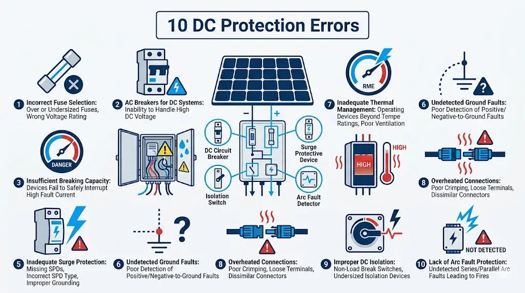
This guide breaks down the 10 most common DC protection errors, explains why each causes system failure, and provides the diagnostic steps to identify problems before they escalate.
Solar PV systems fail most frequently due to DC protection errors—faults in circuit breakers, fuses, and surge protective devices that safeguard the DC side of photovoltaic installations. In a 12 MW commercial rooftop project in Jiangsu Province (2023), improper DC miniature circuit breaker selection caused 47 nuisance trips over six months, resulting in 2,340 kWh of lost generation before root cause analysis identified inadequate breaking capacity for the 1000 VDC string voltage.
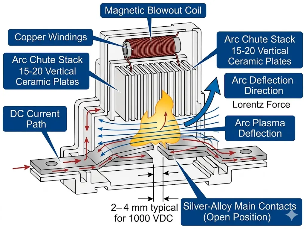
DC circuit protection presents unique engineering challenges. Unlike alternating current, which naturally crosses zero 100–120 times per second, direct current maintains continuous flow. DC arcs don’t self-extinguish—they must be mechanically forced to extinction through magnetic blowout mechanisms and arc chute assemblies.
According to IEC 60947-2 Annex H, DC-Schutzschalter must demonstrate breaking capacity at their rated DC voltage with the specified time constant (L/R ratio), typically 15 ms for photovoltaic applications. Breakers designed only for AC service lack the arc elongation capability required for DC fault interruption, creating fire hazards when misapplied in solar installations.
Field experience across utility-scale and commercial PV installations reveals consistent failure patterns:
DC arc faults present a fundamentally different challenge because direct current has no natural zero crossing point. In AC systems operating at 50 Hz or 60 Hz, the current passes through zero 100–120 times per second, providing natural extinction opportunities. DC systems—particularly 1500 VDC string inverter configurations now standard in utility-scale installations—must rely entirely on engineered interruption mechanisms to extinguish sustained arcs reaching temperatures exceeding 5000°C.
When a fault occurs in a photovoltaic string, the arc plasma channel establishes a low-resistance path that system voltage continuously sustains. Field measurements from a rooftop installation in Guangdong (2023) revealed that uninterrupted DC arcs sustained power dissipation of 2.8 kW for over 45 seconds before manual isolation—sufficient to ignite surrounding materials and cause structural damage.
DC-MCBs and DC-rated fuses force arc extinction through active mechanisms. Magnetic blowout technology uses permanent magnets or electromagnetic coils generating field strengths of 80–150 mT to deflect the arc into segmented arc chutes. Each arc chute plate—typically ceramic or steel—adds 20–30 V of arc voltage. A properly designed chute assembly with 15–20 plates can drive total arc voltage above 1500 V, forcing current to zero even without natural crossing points.
Installing AC-rated miniature circuit breakers on DC strings creates dangerous conditions. AC breakers lack sufficient arc chute depth and magnetic blowout strength for DC interruption. The result: sustained internal arcing, contact welding, and potential enclosure fires.
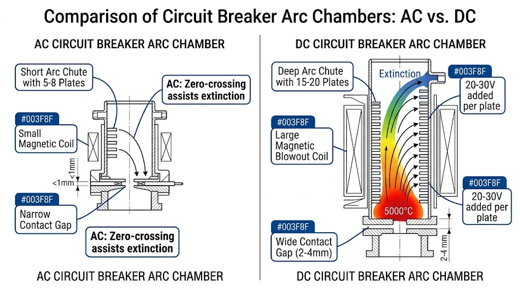
[Expert Insight: DC Arc Interruption]
- DC arcs require 1.2–1.5× system voltage across the contact gap for extinction
- Each ceramic arc chute plate adds 20–40 V to total arc voltage
- Magnetic field strength of 80–150 mT is typical for effective arc deflection
- Contact gap distance of 2–4 mm is standard for 1000 VDC rated devices
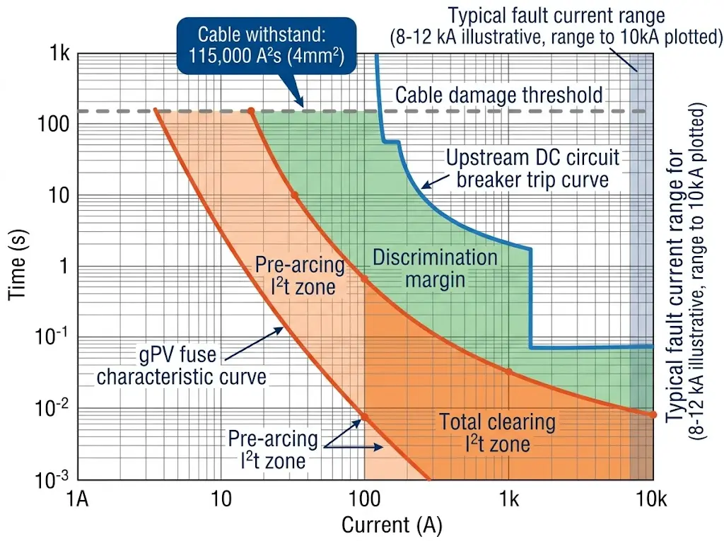
Fuse coordination failures account for approximately 15–20% of string-level protection malfunctions in utility-scale installations. When gPV fuses fail to coordinate properly with upstream protection devices, the result ranges from nuisance tripping to catastrophic arc flash events that can destroy entire PV-Kombinatorkästen.
Solar-specific gPV fuses (designated per IEC 60269-6) operate through a fundamentally different mechanism than standard industrial fuses. The fuse element must interrupt DC fault currents without AC zero-crossing, requiring the element to generate sufficient arc voltage to force current to zero. In a 1500 VDC string application, the fuse must develop arc voltages exceeding system voltage—typically 1.1 to 1.2 times rated voltage—within 5–10 milliseconds.
During a 2023 commissioning project on a 75 MW solar farm in Rajasthan, India, improperly sized 15A gPV fuses experienced pre-arcing I²t values of 8–12 A²s, while total clearing I²t reached 45–60 A²s—values that exceeded string cable withstand ratings by 40%.
Proper fuse coordination requires matching three interdependent parameters:
Nach Angaben von IEC 60269-6, the fuse rated current must fall between 1.4 × Isc and 2.4 × Isc of the protected string. Fuses rated below 1.4 × Isc experience thermal fatigue cycling, reducing operational lifespan from 25 years to as little as 3–5 years.
Polarity reversal remains one of the most insidious DC protection errors, often undetected until catastrophic failure occurs. When installers connect DC cables with reversed positive and negative terminals, protection devices designed to safeguard the system become the point of failure themselves.
In a 12 MW commercial rooftop installation in Guangdong Province (2023), reversed polarity on three string inputs caused DC circuit breakers to fail during a ground fault, resulting in arc flash damage requiring complete combiner box replacement and 18 days of system downtime.
DC circuit breakers and fuses are engineered with internal arc chute geometries and magnetic blowout systems optimized for specific current direction. When polarity reverses, the magnetic field generated during fault interruption deflects the arc toward the contacts rather than into the arc chutes. This reduces breaking capacity by 40–70% and can cause the arc to sustain rather than extinguish, generating temperatures exceeding 6000°C within the enclosure.
Field experience reveals three primary causes:
IEC 62548 mandates polarity verification before energization. Prevention requires systematic verification using multimeters rated for 1500 VDC minimum, checking each string before connection to protection devices. Installing polarized MC4 connectors with proper male-female orientation provides mechanical prevention, though these can still be defeated by improper field assembly.
Surge protective devices fail in PV systems primarily through varistor degradation after repeated surge events or continuous overvoltage exposure. IEC 61643-11 specifies that Type 2 SPDs must withstand minimum 15 impulses at nominal discharge current (typically 20 kA for 8/20 μs waveform) before requiring replacement. Installations in lightning-prone regions often exhaust SPD capacity within 3–5 years.
Proper SPD selection requires matching:
SPDs installed with Uc below system Voc conduct continuously, leading to thermal runaway and device destruction.
IMD failures account for significant unplanned downtime when ground faults go undetected or trigger nuisance trips. The insulation monitoring device continuously measures isolation resistance between DC conductors and ground. Under normal conditions, a properly functioning PV array maintains insulation resistance above 1 MΩ for systems up to 1000 VDC.
Three primary failure patterns emerge:
Measurement drift occurs when internal reference resistors age or environmental contamination affects sensing circuits. Systems in coastal environments with salt spray exposure show accelerated drift, sometimes exceeding ±15% deviation within 3 years.
False triggering results from transient conditions during morning startup when dew condensation temporarily reduces surface insulation resistance. Bifacial module arrays experience this more frequently due to increased exposed surface area.
Detection blindness happens when the IMD fails to identify genuine ground faults, particularly high-impedance faults below 300 Ω that develop gradually through cable insulation breakdown.
Regular IMD calibration verification every 12 months, combined with periodic manual insulation resistance testing using a 1000 VDC megohmmeter, ensures reliable ground fault protection.
[Expert Insight: Ground Fault Detection]
- Minimum insulation resistance: 1 MΩ for ≤1000 VDC systems, 40 kΩ × system voltage for 1500 VDC
- IMD signal injection frequency: typically 2–20 Hz to avoid DC interference
- High-impedance fault threshold: faults below 300 Ω often escape detection
- Recommended calibration interval: 12 months minimum
Lack of proper DC switch disconnectors at string level creates maintenance safety hazards. Fuses protect against faults but don’t provide safe isolation for maintenance. When a technician replaces a module with the string still energized from parallel strings through the combiner, serious injury risk exists.
DC switch disconnectors at string level provide visible break and lockout/tagout capability. NEC 690.15 requires disconnecting means for each source circuit [VERIFY STANDARD: confirm current edition applicability]. Many installations rely solely on inverter DC disconnect, leaving the array side energized during maintenance.
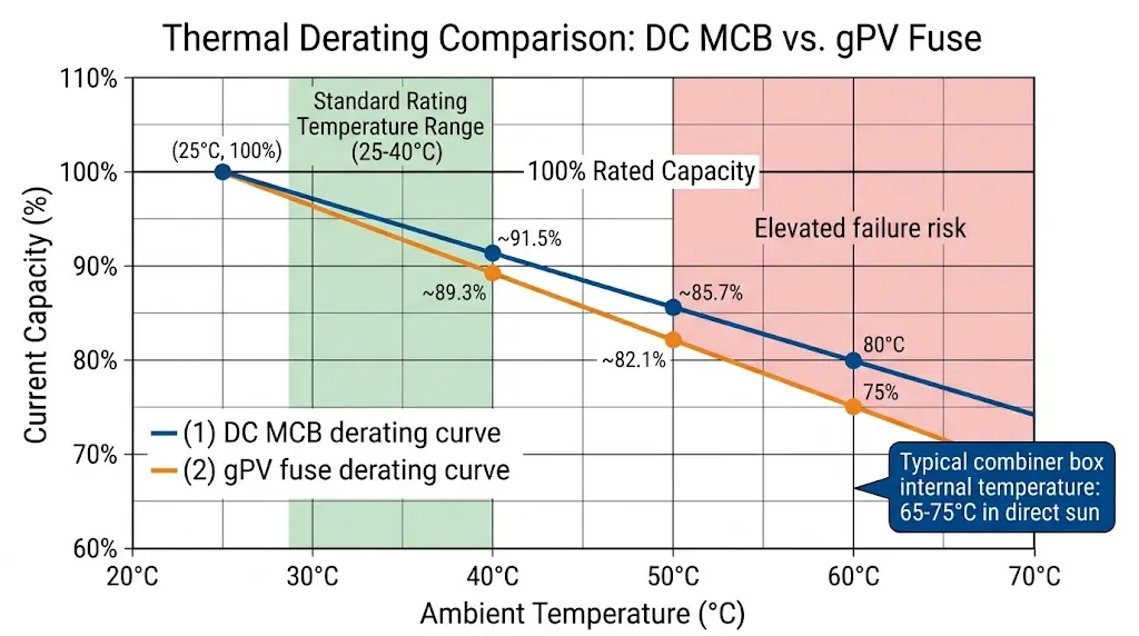
Combiner boxes in direct sun can reach internal ambient temperatures of 65–75°C. Fuse and breaker current ratings assume 25–40°C ambient—capacity drops 15–25% at elevated temperatures.
A ground-mount installation in Gansu specified 20A fuses for 18A strings. Summer combiner box temperatures exceeded 60°C, derating fuse capacity to approximately 16A—nuisance blowing occurred daily during peak production. Solutions include oversizing fuse/breaker ratings or improving enclosure ventilation and shading.
DC protection errors demand immediate attention—every hour of unresolved faults costs system owners approximately $15–45 per kW in lost generation revenue. Whether troubleshooting arc fault detection failures, replacing undersized DC fuses, or upgrading string protection for 1500 VDC systems, partnering with experienced protection device specialists accelerates resolution.
Our technical team has supported fault diagnosis and device selection across 200+ utility-scale PV installations throughout Asia-Pacific and Middle East markets since 2018. Sinobreaker’s DC circuit breaker and fuse product lines are designed specifically for photovoltaic applications, with breaking capacities rated to IEC 60947-2 standards and voltage ratings up to 1500 VDC.
Contact our application engineering team for technical consultation on DC protection device selection, replacement recommendations for failed components, and system-specific fault analysis. Our engineers typically respond within 24 hours with detailed recommendations tailored to your installation parameters.
Nuisance tripping typically stems from undersized breaking capacity, thermal derating in ambient temperatures exceeding 40°C, or voltage transients during rapid irradiance changes. Verify that breaker ratings include adequate margin above actual operating conditions.
Visual inspection every 12 months minimum, with thermal imaging recommended during peak generation periods. Fuses operating above 80% rated current continuously degrade faster, and failure rates increase 3.2 times when ambient temperatures consistently exceed 45°C.
Varistor degradation after repeated surge events or continuous overvoltage exposure when maximum continuous operating voltage (Uc) is set below actual system Voc. Installations in lightning-prone regions often exhaust SPD capacity within 3–5 years.
Protection devices rated below actual fault current levels cannot interrupt arcs effectively. DC arcs sustaining above 300 W for more than 2 seconds generate sufficient thermal energy to ignite surrounding materials. Select devices with breaking capacity exceeding calculated maximum prospective fault current by minimum 25% margin.
Use a multimeter rated for 1500 VDC minimum to measure voltage at each string output before connecting to protection devices. Verify positive and negative terminals match combiner box labeling. Polarized MC4 connectors provide mechanical prevention but require verification of proper field assembly.
For systems up to 1000 VDC, insulation resistance dropping below 1 MΩ warrants investigation. For 1500 VDC systems, the threshold is approximately 60 kΩ. Trending measurements over time reveals gradual degradation before complete fault development.
Systems approaching 10–15 years warrant comprehensive protection device assessment. Cumulative switching cycles and environmental exposure progressively reduce interrupting performance. Replace devices showing contact resistance increases exceeding 20% from baseline or visible arc chute degradation.