Dirección
304 North Cardinal
Dorchester Center, MA 02124
Horas de trabajo
De lunes a viernes: de 7.00 a 19.00 horas
Fin de semana: 10.00 A 17.00 HORAS
Dirección
304 North Cardinal
Dorchester Center, MA 02124
Horas de trabajo
De lunes a viernes: de 7.00 a 19.00 horas
Fin de semana: 10.00 A 17.00 HORAS

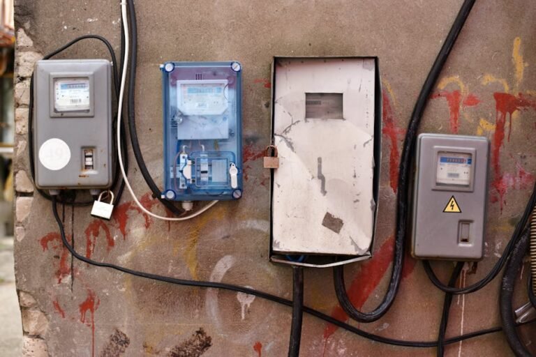
Los disyuntores de CC de 12 voltios son la columna vertebral de la protección eléctrica en los sistemas de automoción, náuticos y de vehículos recreativos (RV). A diferencia de los disyuntores de CA domésticos, estos dispositivos especializados protegen los circuitos de CC de bajo voltaje de condiciones de sobrecorriente en baterías, sistemas de carga solar, inversores y circuitos de accesorios.
Esta completa guía cubre todo lo que necesita saber para seleccionar, dimensionar, instalar y solucionar problemas de disyuntores de CC de 12 V para aplicaciones móviles y aisladas de la red.
Los sistemas de 12 voltios funcionan con características eléctricas significativamente diferentes en comparación con los sistemas de CC de mayor tensión:
- Menor tensión, mayor corriente: Una carga de 1200W a 12V consume 100A (frente a 12A a 120V AC)
- Retos de la supresión de arcos: Los arcos de CC no se extinguen de forma natural como los de CA
- Gestión térmica: El elevado flujo de corriente genera mucho calor
- Consideraciones sobre la polaridad: Los sistemas de CC requieren conexiones positivas/negativas adecuadas
- Características de descarga de la batería: La caída de tensión afecta al rendimiento del disyuntor
Aplicaciones clave:
- Sistemas eléctricos de automoción (coches, camiones, motocicletas)
- Embarcaciones marítimas (barcos, yates, veleros)
- Autocaravanas y campers
- Sistemas de baterías solares sin conexión a la red
- Carros de golf y vehículos eléctricos
- Maquinaria agrícola
- Sistemas de alimentación de emergencia
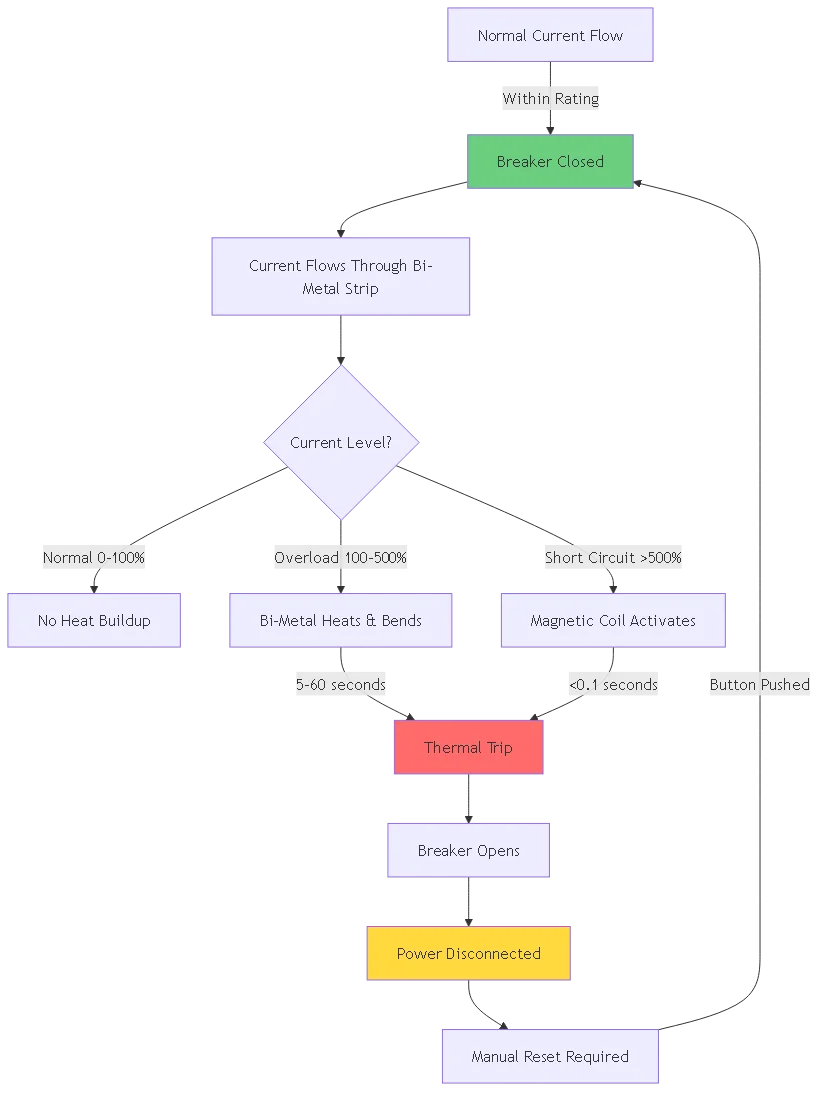
Un disyuntor de CC de 12 voltios protege los circuitos eléctricos mediante dos mecanismos principales:
1. Mecanismo de disparo térmico
- La banda bimetálica se calienta con el flujo de corriente
- Una corriente excesiva hace que la banda se doble
- La conexión mecánica abre el interruptor
- Tiempo de respuesta: 5-60 segundos en función de la gravedad de la sobrecarga
2. Mecanismo de disparo magnético
- La bobina crea un campo magnético
- Las corrientes de defecto elevadas producen una fuerte fuerza magnética
- La armadura tira mecánicamente para disparar el disyuntor
- Tiempo de respuesta: <0,1 segundos para cortocircuitos Operación de rearme manual:
La mayoría de los disyuntores de 12 V disponen de mecanismos de restablecimiento de tipo pulsador o interruptor, lo que permite a los usuarios restablecer la alimentación tras eliminar la condición de fallo.
#### Tipo 1: Interruptores automáticos de rearme por pulsador
- Descripción: El botón rojo de reinicio sobresale cuando se dispara
- Lo mejor para: Lugares de fácil acceso
- Ventajas: Indicación visual de disparo, rearme rápido
- Valoraciones comunes: 5A a 100A
- Uso típico: Paneles marinos, accesorios de automoción
#### Tipo 2: Interruptores de palanca
- Descripción: Parece un interruptor estándar, se apaga cuando se dispara.
- Lo mejor para: Paneles de control que requieren la función de interruptor
- Ventajas: Doble función (disyuntor + interruptor)
- Valoraciones comunes: 10A a 50A
- Uso típico: Cuadros eléctricos de vehículos recreativos, controles de equipos
#### Tipo 3: Interruptores automáticos de rearme automático
- Descripción: Se restablece automáticamente tras un periodo de enfriamiento
- Lo mejor para: Lugares inaccesibles, protección del motor
- Ventajas: No requiere intervención manual
- Valoraciones comunes: 5A a 40A
- Uso típico: Bombas de achique, ventiladores de refrigeración
#### Tipo 4: Montaje en superficie vs. Montaje en panel
- Montaje en superficie: Se atornilla directamente a la superficie, terminales expuestos
- Montaje en panel: Se instala a través del recorte del panel, terminales protegidos
- Factor de selección: Espacio disponible y necesidades de protección del medio ambiente
Los disyuntores de 12 V CC suelen tener valores nominales de tensión:
- 12 V nominales: Sistemas estándar de automoción/marinos
- 32 V CC máximo: Proporciona un margen de seguridad para los picos de tensión
- 48 V CC nominal: Puede utilizarse en sistemas de 12 V (sobrevalorado)
Importante: No utilice nunca un disyuntor por debajo de la tensión máxima del sistema, incluidas las tensiones de carga (14,4 V para sistemas de 12 V).
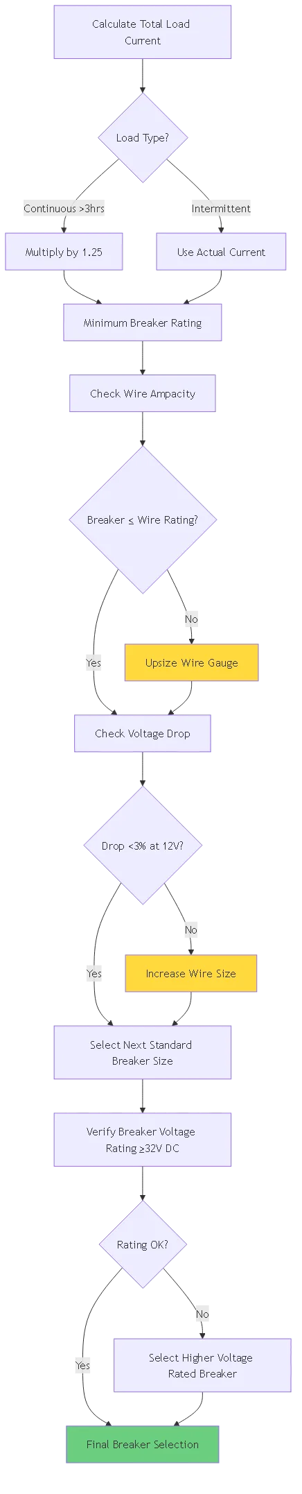
Artículo 690 de NEC.8 Requisito (aplicable a sistemas solares/baterías):
El valor nominal del disyuntor debe ser de al menos 125% de corriente continua máxima
Fórmula:
Capacidad del disyuntor (A) = Corriente continua (A) × 1,25
Ejemplo de cálculo:
- Inversor de 12 V que consume 60 A continuos
- Interruptor requerido: 60A × 1,25 = 75A mínimo
- Seleccione: Disyuntor 80A (siguiente tamaño estándar superior)
El disyuntor debe proteger el cable, no sólo la carga:
| Calibre del cable (AWG) | Ampacidad máxima | Rompedor recomendado |
|---|---|---|
| 18 AWG | 16A | 15 A máx. |
| 16 AWG | 22A | 20 A máx. |
| 14 AWG | 32A | 30 A máx. |
| 12 AWG | 41A | 40 A máx. |
| 10 AWG | 55A | 50 A máx. |
| 8 AWG | 73A | 70 A máx. |
| 6 AWG | 101A | 100 A máx. |
| 4 AWG | 135A | 125 A máx. |
| 2 AWG | 181A | 175 A máx. |
| 1/0 AWG | 245A | 225 A máx. |
Regla crítica: El valor nominal del disyuntor NUNCA debe superar el valor nominal de ampacidad del cable.
Paso 1: Inventario de todas las cargas
Ejemplo de sistema RV 12V:
- Luces LED: 15A
- Bomba de agua 8A
- Nevera 12A
- Inversor: 80A
- Ventilador: 3A
Total: 118A
Paso 2: Aplicar el factor de demanda
No todas las cargas funcionan simultáneamente. Utilice una demanda realista:
- Cargas esenciales: 100% (luces, bomba de agua)
- Cargas intermitentes: 50% (inversor, frigorífico)
Paso 3: Calcular el disyuntor necesario
Cargas continuas: 15A + 8A = 23A
Intermitente: (80A + 12A) × 0,5 = 46A
Demanda total: 23A + 46A = 69A
Interruptor necesario: 69A × 1,25 = 86,25A → Utilice un interruptor de 100A
A 12 V, la caída de tensión afecta significativamente al rendimiento:
Fórmula de caída de tensión:
Caída de tensión (V) = 2 × Longitud (ft) × Corriente (A) × Resistencia (Ω/ft) / 1000
Ejemplo:
- Cable 10 AWG, longitud 20 pies
- Consumo de corriente de 50 A
- Resistencia: 1,24 Ω por 1000 pies
Caída = 2 × 20 × 50 × 1,24 / 1000 = 2,48V
12,0V - 2,48V = 9,52V en carga (caída 20% - INACEPTABLE)
Solución: Aumente el tamaño del cable para reducir la resistencia, lo que puede permitir un disyuntor más pequeño debido a la menor generación de calor.
Normas marinas y para vehículos recreativos (ABYC/RVIA):
1. Accesibilidad
- De fácil acceso para desconexión de emergencia
- Altura: 3-6 pies sobre el nivel del suelo
- Etiquetado claro y visible con poca luz
2. Protección del medio ambiente
- Preferiblemente en un lugar seco
- Interruptores con clasificación IP67 para lugares húmedos
- Cajas de paneles cubiertas en zonas expuestas
3. Despeje térmico
- Espacio libre mínimo de 5 cm alrededor del disyuntor
- Ventilación adecuada para disipar el calor
- Lejos de fuentes de calor (motor, tubo de escape)
4. Protección de cable positivo
- Interruptor sólo en el lado positivo (+)
- A menos de 7 pulgadas de la batería (NEC 690.71)
- Antes de cualquier división o ramificación
Herramientas necesarias:
- Pelacables (gama 12-18 AWG)
- Herramienta de crimpado para terminales
- Multímetro (comprobación de tensión)
- Destornillador dinamométrico (si se especifica)
- Tubo termorretráctil
- Conectores de terminales marinos
Procedimiento de instalación:
Paso 1: Aislamiento de la alimentación
1. Desconectar el borne negativo de la batería
2. Verifique 0V a través de los terminales positivos con el multímetro
3. Espere 5 minutos a que se descargue el condensador
4. Utilice herramientas aisladas en todo
Paso 2: Preparación del cable
1. Corte el cable a la longitud necesaria (reduzca al mínimo la longitud sobrante)
2. Pele el aislamiento 3/8 de pulgada
3. Engarce los terminales (utilice una engarzadora de trinquete)
4. Aplique termorretráctil sobre la conexión engarzada
5. 5. Prueba de tracción: Tire con una fuerza de 25 libras
Paso 3: Montaje del disyuntor
1. Montaje en superficie: Utilizar tornillería de acero inoxidable.
2. Montaje en panel: Encaje a presión en el recorte del panel
3. Verificar la seguridad mecánica (sin tambaleo).
4. Compruebe la orientación de los terminales (positivo hacia el lado de carga)
Paso 4: Conexiones de terminales
1. Conecte primero el terminal del lado de la batería
2. Apriete al par especificado (normalmente 15-25 in-lbs)
3. Conecte el terminal del lado de carga
4. Verifique que no haya conductores expuestos
5. 5. Aplique grasa dieléctrica a los terminales
Paso 5: Pruebas
1. Vuelva a conectar el negativo de la batería
2. Compruebe la tensión en el disyuntor (debe indicar ~12,6 V).
3. Restablezca el disyuntor a la posición ON
4. Verifique la tensión en el lado de carga
5. Pruebe la función de disparo (si es posible con el botón de prueba)
6. Etiquetar el disyuntor con el nombre del circuito y el amperaje
❌ Error 1: Instalación del disyuntor en el lado negativo
- Por qué equivocado: La masa del chasis puede puentear el disyuntor
- Correcto: Instalar siempre en el cable positivo
❌ Error 2: Cable subdimensionado para la capacidad del disyuntor
- Por qué equivocado: El disyuntor no protege el cable del sobrecalentamiento
- Correcto: Ampacidad del cable ≥ potencia del disyuntor
❌ Error 3: Varios circuitos en un solo disyuntor
- Por qué equivocado: Imposible identificar el circuito defectuoso
- Correcto: Un disyuntor por circuito
❌ Error 4: Utilización de un disyuntor de CA para CC
- Por qué equivocado: Los disyuntores de CA no extinguen el arco de CC
- Correcto: Utilice únicamente disyuntores de corriente continua
❌ Error 5: Sin etiquetado
- Por qué equivocado: Las situaciones de emergencia requieren una identificación rápida
- Correcto: Etiqueta con el nombre del circuito y el amperaje
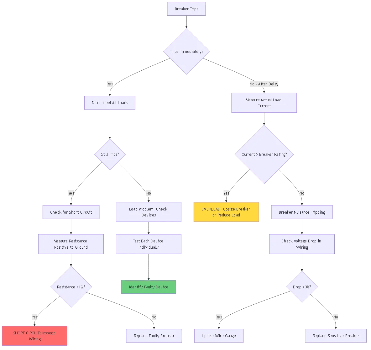
Síntoma: El disyuntor se dispara inmediatamente al restablecerse
Procedimiento de diagnóstico:
1. Aislar la carga
- Desconecte todas las cargas del disyuntor
- Reiniciar disyuntor
- Si se mantiene: Problema de carga
- Si se dispara: Interruptor o problema de cableado
2. Medir la corriente de carga
“`
- Utilice una pinza amperimétrica de CC en el cable positivo
- Comparar con el valor nominal del disyuntor
- Si >100% nominal: Condición de sobrecarga
- Si el valor nominal es <80%: Fallo del interruptor “`
3. Comprobación de cortocircuitos
“`
- Poner el multímetro en modo resistencia
- Medida de positivo a negativo/tierra
- La lectura <1 Ω indica cortocircuito - Inspeccione el cableado en busca de daños/rozaduras “`
4. Verificar el tamaño del cable
“`
- Medir el calibre del cable con la herramienta de calibre
- Comparar con el valor nominal del disyuntor
- Un cable demasiado pequeño provoca una caída de tensión y calor
- Sustituir por cable de calibre adecuado
“`
5. Prueba de funcionamiento del interruptor
“`
- Aplicar carga de prueba calibrada
- La carga debe ser 135% del valor nominal del disyuntor
- El disyuntor debe dispararse en 1-60 segundos
- Si no se dispara: Sustituir el disyuntor
“`
Posibles causas:
| Síntoma | Causa | Solución |
|---|---|---|
| Botón atascado | Atasco mecánico | Golpear firmemente, lubricar el pivote |
| El botón se pulsa pero no se cierra | Mecanismo de cierre roto | Sustituir disyuntor |
| Caliente al tacto | Bloqueo térmico activo | Enfriar 15 min, reintentar |
| Daños visibles | Daños físicos | Sustituir inmediatamente |
Caída de tensión normal:
- Interruptor cerrado: Caída de 0,1-0,3 V a corriente nominal
- Ejemplo: entrada 11,9V, salida 11,7V = 0,2V (aceptable)
Caída de tensión excesiva:
- Una caída de >0,5 V indica un problema
- Causas: Terminales corroídos, conexiones sueltas, resistencia interna.
- Solución: Limpiar los terminales, apretar las conexiones o sustituir
Procedimiento de prueba:
1. Conecte el voltímetro al positivo de la batería: Registre la tensión
2. 2. Conecte el voltímetro a la entrada del disyuntor: Debe coincidir con la batería
3. 3. Conecte el voltímetro a la salida del disyuntor: Calcule la caída
4. 4. Cargar el circuito a 80% del valor nominal del disyuntor.
5. Repita las mediciones bajo carga
6. Si la caída es >0,5 V bajo carga: Servicio requerido
Protección contra la corrosión:
- Requiere clasificación marina UL 489 o IP67
- Herrajes de acero inoxidable obligatorios
- Revestimiento conformado de placas de circuitos
- Compartimentos de terminales sellados
Normas ABYC (American Boat & Yacht Council):
- E-11: Sistemas eléctricos de CA y CC
- Exigir protección contra la ignición en espacios con motores de gasolina
- Interruptores a menos de 7 pulgadas de la batería
- Código de colores: Rojo (positivo no conmutado), Amarillo (positivo conmutado)
Marcas recomendadas para Marina:
- Blue Sea Systems (más popular)
- Tecnologías Carling
- Ancor (cable marino + disyuntores)
Consideraciones sobre la doble batería:
- Disyuntores separados para la batería de la casa y la del chasis
- Aislador de batería o circuitos combinadores
- Integración del regulador de carga solar
Sistemas de 120 V CA a 12 V CC:
- Protección de salida del convertidor/cargador
- Valores típicos: 30-60A para la salida del convertidor
- Interruptor independiente para el lado de entrada de CA
Disposición típica del panel de disyuntores de 12 V para vehículos recreativos:
Desconexión de la batería principal: 150-200A
├─ Luces interiores: 15A
├─ Bomba de agua: 15A
├─ Soplador del horno: 25A
├─ Frigorífico (modo CC): 15A
├─ Inversor: 150A (dedicado)
├─ Motores de las correderas: 30A
├─ Tomas de 12V: 20A
└─ Sistema de entretenimiento: 20A
Requisitos de desconexión de la batería:
- Fusible o disyuntor de clase T a menos de 7 pulgadas de la batería
- Potencia: 1,25× corriente máxima del regulador de carga
- Típico: 80-125A para sistemas residenciales
Integración del controlador de carga:
- El disyuntor de salida protege el cableado de la batería
- El disyuntor de entrada protege el controlador de la batería
- Debe soportar las sobrecorrientes de arranque
Sistemas de audio de alta potencia:
- Interruptor cerca de la batería obligatorio
- Calcular el tamaño del cable para el consumo máximo
- Típico: 100-200A para sistemas de competición
Iluminación auxiliar:
- Barras de luces LED: 10-30A típico
- El disyuntor facilita el encendido y apagado sin interruptor
- Fusible de cuchilla en línea como protección secundaria
Circuitos de cabrestante:
- 150-300A según la potencia del cabrestante
- Rompedor dedicado para cargas pesadas
- La protección térmica es fundamental para tiradas largas
Inspección mensual:
- Comprobación visual de corrosión en los terminales
- Compruebe que el disyuntor se reinicia sin problemas
- Compruebe si hay decoloración por calor
- Comprobación de conexiones sueltas
Mantenimiento anual:
- Limpie los terminales con un limpiador de contactos eléctricos
- Aplique grasa dieléctrica nueva
- Prueba de la función de disparo bajo carga
- Verifique que las etiquetas de clasificación de corriente sean correctas
Sustitución por 5 años:
- Entornos marinos: Sustituir cada 5-7 años
- Automoción: más de 10 años de vida útil
- Aplicaciones de ciclo alto: 3-5 años
1. Tropiezos molestos: Se dispara repetidamente por debajo de la corriente nominal
2. No se reinicia: Fallo mecánico del pestillo
3. Disparo retardado: Tarda demasiado en 135% sobrecarga
4. Sobrecalentamiento: Generación excesiva de calor con corriente normal
5. Corrosión: La corrosión visible de los terminales no se puede limpiar
6. Daños físicos: Grietas, quemaduras, plástico derretido
- Los disyuntores contienen metales reciclables
- No tirar a la basura general
- Llevar al centro de reciclaje de aparatos electrónicos
- Algunas tiendas de repuestos de automóviles aceptan para su reciclaje
Blue Sea Systems 7074 - Montaje en superficie 50A
- Precio: $25-30
- Características: Clasificación IP67, protegido contra ignición
- Lo mejor para: Instalaciones marítimas
- Garantía2 años
Carling Technologies 2-5800-203-050
- Precio: $18-24
- Características: Disparo magnético hidráulico, 10.000 ciclos
- Lo mejor para: Equipamiento comercial
- Garantía: 3 años
Bussman CB185-50
- Precio: $12-16
- Características: Montaje en superficie, opción de restablecimiento automático
- Lo mejor para: Paneles RV
- Garantía: 1 año
Eaton / Bussmann Serie 121
- Precio: $8-14
- Características: Montaje en panel, diseño compacto
- Lo mejor para: Accesorios para automóviles
- Garantía: 1 año
ANJOSHI 12V Pulsador Reset
- Precio: $6-10
- Características: Protección térmica básica
- Lo mejor para: Circuitos no críticos
- Garantía: 30 días
Qiorange Inline Impermeable
- Precio: $5-8
- Características: Carcasa con clasificación IP67
- Lo mejor para: Accesorios de exterior
- Garantía: Ninguno
Marina especializada:
- West Marine
- Defender Marine
- Abastecimiento pesquero
Específico para vehículos recreativos:
- Camping World
- PPL Autocaravanas
- RecPro
Automoción general:
- Amazon (la selección más amplia)
- AutoZone
- O'Reilly Auto Parts
| Característica | Disyuntor de CC | Fusibles de automoción |
|---|---|---|
| Restablecer | Rearme manual | Debe reemplazar |
| Coste | $10-30 cada uno | $0,50-2 c/u |
| Duración del viaje | 5-60 segundos | <0,1 segundos |
| Precisión | ±20% | ±10% |
| Mejor uso | Viajes frecuentes previstos | Protección única |
| Conveniencia | Muy alta | Bajo (necesita repuestos) |
Cuándo utilizar cada uno:
- Interruptores: Lugares accesibles, circuitos accionados por el usuario
- Fusibles: Circuitos críticos de seguridad, protección de reserva
| Característica | Interruptor automático | Interruptor manual |
|---|---|---|
| Protección contra sobrecorriente | Sí | No |
| Control manual | Sí | Sí |
| Coste | Más alto | Baja |
| Seguridad | Viaje automático | Sólo manual |
Buenas prácticas: Utilice un disyuntor para la protección + un interruptor independiente para el control (doble protección).
1. ¿Puedo utilizar un disyuntor de 12 V CC en un sistema de 24 V?
No, nunca supere la tensión nominal. Un disyuntor de 12 V en un sistema de 24 V fallará catastróficamente y no podrá interrumpir con seguridad arcos de CC a tensiones más altas. Utilice siempre un disyuntor de al menos 32 V CC para sistemas de 24 V, preferiblemente de 50 V CC.
2. ¿Por qué se dispara el disyuntor de 12 V al arrancar el motor?
Los motores de arranque consumen entre 200 y 400 A de corriente de arranque durante 1-3 segundos. Si su disyuntor está protegiendo accesorios en el mismo circuito, la caída de tensión y el pico de corriente pueden causar disparos molestos. Solución: Instale un disyuntor independiente de mayor capacidad para el circuito de arranque o utilice un disyuntor de disparo retardado.
3. ¿Cuál es la diferencia entre disyuntores térmicos y magnéticos?
Los disyuntores térmicos utilizan una banda bimetálica que se dobla con el calor (respuesta de 5-60 segundos), protegiendo contra sobrecargas. Los magnetotérmicos utilizan una bobina de solenoide para un disparo instantáneo (<0,1 segundos), protegiendo contra cortocircuitos. La mayoría de los disyuntores de 12 V combinan ambas tecnologías (térmica-magnética) para una protección completa.
4. ¿Cómo puedo saber si mi disyuntor de 12 V está preparado para corriente continua?
Compruebe que la etiqueta del disyuntor indica “CC” y la tensión nominal (por ejemplo, “32 V CC”). Los disyuntores sólo de CA mostrarán el símbolo “AC” o “~”. Nunca utilice un disyuntor de CA para aplicaciones de CC: los disyuntores de CA no pueden interrumpir con seguridad los arcos de CC. Busque las marcas UL 489 (CA y CC) o UL 1077 (suplementario).
5. ¿Puedo poner en paralelo dos disyuntores de 50 A para obtener una capacidad de 100 A?
No, nunca ponga los disyuntores en paralelo. La corriente no se repartirá uniformemente debido a ligeras diferencias en la resistencia interna, haciendo que un disyuntor soporte más carga y se dispare primero. En su lugar, utilice un solo disyuntor para toda la corriente necesaria o instale circuitos separados.
6. ¿Cuál es la causa de la caída de tensión en mi disyuntor de 12 V?
La caída de tensión normal es de 0,1-0,3 V a la corriente nominal debido a la resistencia interna de los contactos. Una caída excesiva (>0,5V) indica terminales corroídos, conexiones sueltas o degradación interna del interruptor. Limpie y apriete todas las conexiones; si la caída persiste, sustituya el interruptor.
7. ¿Debo instalar un disyuntor en los cables positivo y negativo?
No, sólo instale el disyuntor en el cable positivo (+). El cable negativo debe conectarse directamente a tierra/chasis. Instalar un disyuntor en el lado negativo no proporciona ninguna protección adicional, ya que el chasis está conectado a tierra y un fallo puede eludir el disyuntor completamente a través de la ruta de tierra del chasis.
La elección del disyuntor de CC de 12 voltios correcto requiere una cuidadosa consideración de los requisitos de corriente, el tamaño de los cables, las condiciones ambientales y las necesidades específicas de la aplicación. Siga estos principios clave:
Criterios críticos de selección:
1. Clasificación actual ≥ 125% de carga continua
2. Tensión nominal ≥ 32 V CC para sistemas de 12 V
3. Ampacidad del cable ≥ Potencia del disyuntor
4. Protección del medio ambiente (clasificación IP para lugares húmedos)
5. Capacidad de interrupción suficiente para su banco de baterías
Buenas prácticas:
- Dimensione de forma conservadora: no supere continuamente el valor nominal del disyuntor 80%.
- Utilice disyuntores marinos en entornos corrosivos
- Etiquetar claramente todos los disyuntores con el nombre del circuito y el valor nominal.
- Pruebe anualmente la función de disparo
- Sustituya los disyuntores cada 5-10 años en función del entorno
Calidad frente a coste:
Para circuitos de seguridad críticos (bombas de achique, luces de navegación), invierte en marcas de primera calidad como Blue Sea Systems. Para accesorios no críticos (cargadores USB, tiras de LED), basta con disyuntores de automoción de gama media.
Siguiendo esta completa guía, garantizará una protección eléctrica fiable para los sistemas eléctricos de 12 V de su automóvil, embarcación o vehículo recreativo durante muchos años.
No, nunca supere la tensión nominal. Un disyuntor de 12 V en un sistema de 24 V fallará catastróficamente y no podrá interrumpir con seguridad arcos de CC a tensiones más altas. Utilice siempre un disyuntor de al menos 32 V CC para sistemas de 24 V, preferiblemente de 50 V CC.
Los motores de arranque consumen entre 200 y 400 A de corriente de arranque durante 1-3 segundos. Si su disyuntor está protegiendo accesorios en el mismo circuito, la caída de tensión y el pico de corriente pueden causar disparos molestos. Instale un disyuntor independiente de mayor capacidad para el circuito de arranque o utilice un disyuntor de disparo retardado.
Los disyuntores térmicos utilizan una banda bimetálica que se dobla con el calor (respuesta de 5-60 segundos), protegiendo contra sobrecargas. Los magnetotérmicos utilizan una bobina de solenoide para un disparo instantáneo (<0,1 segundos), protegiendo contra cortocircuitos. La mayoría de los disyuntores de 12 V combinan ambas tecnologías para una protección completa.
Compruebe que la etiqueta del disyuntor indica ‘CC’ y la tensión nominal (por ejemplo, ’32 V CC’). Los disyuntores de CA mostrarán el símbolo ‘AC’ o ‘~’. Nunca utilice un disyuntor de CA para aplicaciones de CC: los disyuntores de CA no pueden interrumpir de forma segura los arcos de CC. Busque las marcas UL 489 o UL 1077.
No, nunca ponga los disyuntores en paralelo. La corriente no se repartirá uniformemente debido a ligeras diferencias en la resistencia interna, haciendo que un disyuntor soporte más carga y se dispare primero. En su lugar, utilice un solo disyuntor para toda la corriente necesaria o instale circuitos separados.
La caída de tensión normal es de 0,1-0,3 V a la corriente nominal debido a la resistencia interna de los contactos. Una caída excesiva (>0,5V) indica terminales corroídos, conexiones sueltas o degradación interna del interruptor. Limpie y apriete todas las conexiones; si la caída persiste, sustituya el interruptor.
No, sólo instale el disyuntor en el cable positivo (+). El cable negativo debe conectarse directamente a tierra/chasis. Instalar un disyuntor en el lado negativo no proporciona ninguna protección adicional, ya que el chasis está conectado a tierra.