Dirección
304 North Cardinal
Dorchester Center, MA 02124
Horas de trabajo
De lunes a viernes: de 7.00 a 19.00 horas
Fin de semana: 10.00 A 17.00 HORAS
Dirección
304 North Cardinal
Dorchester Center, MA 02124
Horas de trabajo
De lunes a viernes: de 7.00 a 19.00 horas
Fin de semana: 10.00 A 17.00 HORAS

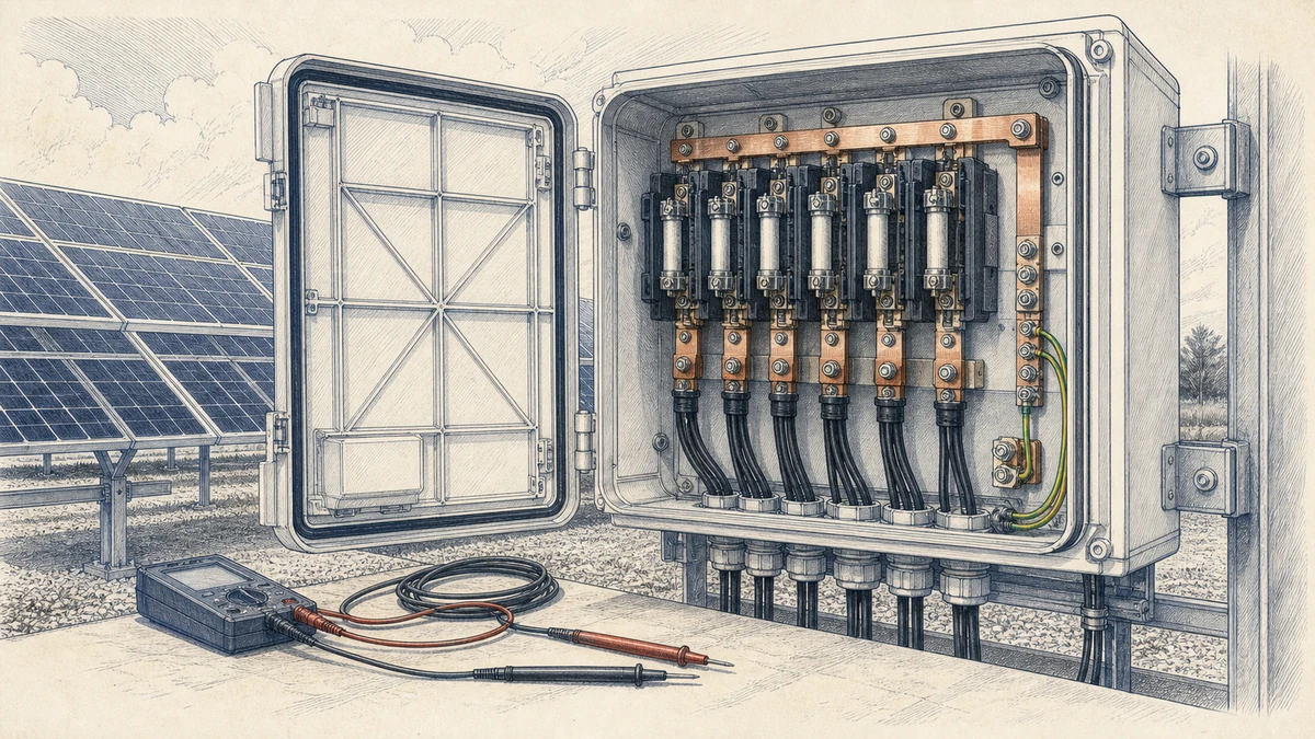
A PV combiner box commissioning test confirms that string inputs, protection devices, internal wiring, grounding, insulation resistance, and output polarity are ready for safe energization. For Sinobreaker PV Combiner Box applications, the test sheet below can be used as a structured field record before connecting the combiner output to the inverter, DC distribution cabinet, or downstream disconnect.
This article focuses on three high-priority commissioning checks: insulation, continuity, and polarity. These checks support the documentation, inspection, and commissioning principles addressed in IEC 62446-1 for grid-connected PV systems. They also reflect common PV commissioning checklist items such as conductor polarity, torque verification, insulation class, and confirming that array open-circuit voltage remains within the permitted equipment limit.
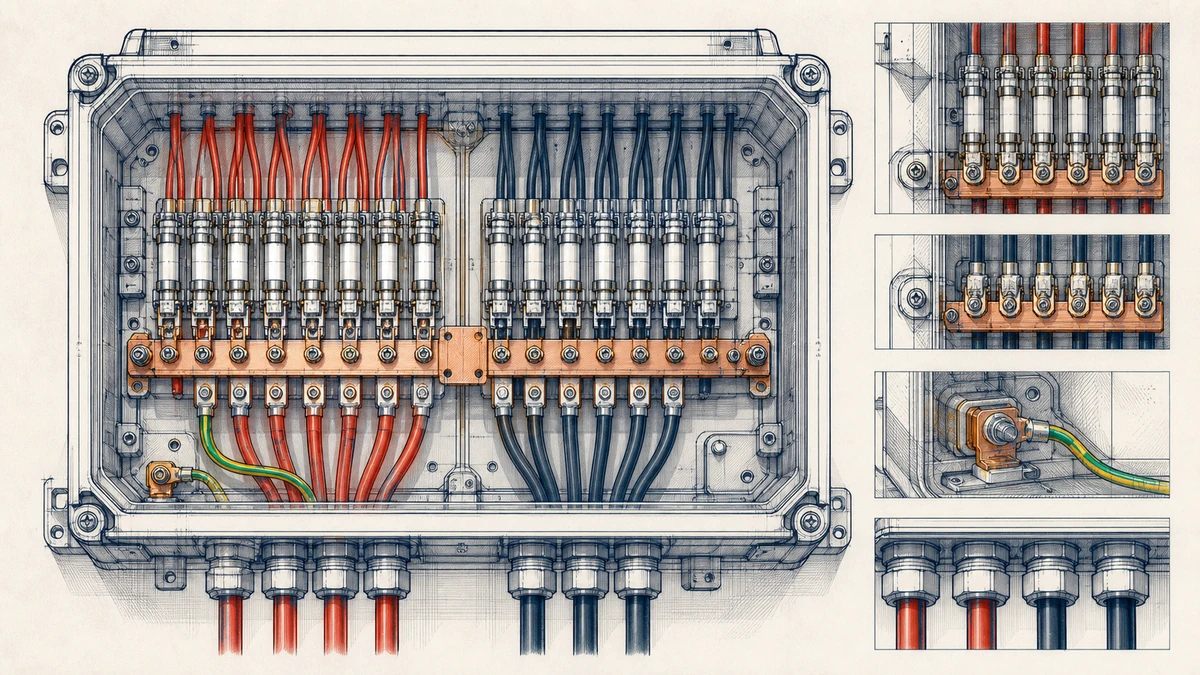
PV combiner boxes operate on live DC sources that can remain energized whenever modules receive light. Testing must be performed by qualified electrical personnel using properly rated instruments and PPE.
Before testing:
Do not perform insulation resistance or dielectric-strength testing through surge protective devices, monitoring electronics, communication modules, or other sensitive components unless the product documentation explicitly permits it.
Use this sheet as a field template for a Sinobreaker PV Combiner Box inspection and electrical verification.
| Project information | Record |
|—|—|
| Project name | |
| Site location | |
| Combiner box ID | |
| Combiner box model | |
| Rated DC voltage | |
| Rated string current | |
| Number of string inputs | |
| Inverter / MPPT ID | |
| Test date | |
| Tested by | |
| Weather condition | |
| Irradiance | |
| Ambient temperature | |
| Module temperature | |
| Required tools | Check |
|—|—|
| DC-rated multimeter | |
| Insulation resistance tester | |
| Continuity tester or low-resistance meter | |
| Clamp meter suitable for DC | |
| Torque wrench | |
| Approved lockout/tagout equipment | |
| PPE suitable for DC PV work | |
| Manufacturer wiring diagram | |
| Site string layout drawing | |
A visual inspection should be completed before electrical measurements. Many commissioning failures are caused by loose terminals, reversed strings, damaged insulation, incorrect fuse ratings, or incomplete labeling.
| Inspection item | Acceptance criterion | Result |
|—|—|—|
| Enclosure installed securely | No movement, deformation, or unsafe mounting | Pass / Fail |
| Door seal and gasket condition | Clean, continuous, and correctly seated | Pass / Fail |
| Cable glands and connectors | Tight, sealed, and suitable for cable diameter | Pass / Fail |
| Drainage and ventilation | No blocked drain or abnormal condensation path | Pass / Fail |
| IP rating condition | No holes, cracks, missing plugs, or damaged covers | Pass / Fail |
| Warning labels | DC danger, polarity, and circuit labels visible | Pass / Fail |
| Inspection item | Acceptance criterion | Result |
|—|—|—|
| DC fuses installed | Correct rating and type for each string | Pass / Fail |
| Fuse holders | Fully seated and undamaged | Pass / Fail |
| DC switch or isolator | Correct rating and mechanical operation | Pass / Fail |
| Surge protective device | Correct voltage class and status indicator normal | Pass / Fail |
| Busbars | No discoloration, deformation, or contamination | Pass / Fail |
| Monitoring module, if installed | Correct wiring and protected from test voltage where required | Pass / Fail |
Loose DC terminals can cause overheating, voltage drop, nuisance shutdown, or arc faults. Verify torque values according to the Sinobreaker product documentation and the terminal manufacturer’s specification.
| Terminal location | Required torque | Measured / confirmed | Result |
|—|—:|—:|—|
| String positive terminals | | | Pass / Fail |
| String negative terminals | | | Pass / Fail |
| Output positive terminal | | | Pass / Fail |
| Output negative terminal | | | Pass / Fail |
| PE / grounding terminal | | | Pass / Fail |
| SPD grounding terminal | | | Pass / Fail |
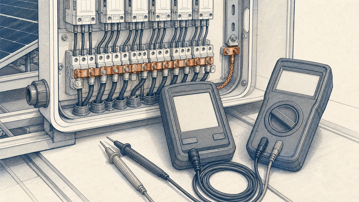
Continuity testing verifies that the protective earth path, internal bonding, and conductor paths are complete before energization.
The protective earth continuity test confirms that exposed conductive parts and grounding points are properly bonded.
| Test point | Method | Acceptance criterion | Result |
|—|—|—|—|
| Enclosure to PE terminal | Continuity / low-resistance test | Continuous bonding path | Pass / Fail |
| Door to enclosure, if bonded | Continuity / low-resistance test | Continuous bonding path | Pass / Fail |
| SPD earth terminal to PE bar | Continuity / low-resistance test | Continuous bonding path | Pass / Fail |
| Cable gland bonding, if metallic | Continuity / low-resistance test | Continuous bonding path | Pass / Fail |
| PE terminal to site grounding conductor | Continuity / low-resistance test | Continuous bonding path | Pass / Fail |
Record measured resistance where project requirements specify a maximum value.
| PE continuity measurement | Value |
|—|—:|
| Enclosure to PE terminal | |
| Door to PE terminal | |
| SPD earth to PE terminal | |
| PE terminal to grounding conductor | |
String continuity confirms that the positive and negative conductors from each PV string are landed on the correct input terminals without open circuits.
| String ID | Positive conductor present | Negative conductor present | Fuse installed | Result |
|—|—|—|—|—|
| String 1 | Yes / No | Yes / No | Yes / No | Pass / Fail |
| String 2 | Yes / No | Yes / No | Yes / No | Pass / Fail |
| String 3 | Yes / No | Yes / No | Yes / No | Pass / Fail |
| String 4 | Yes / No | Yes / No | Yes / No | Pass / Fail |
| String 5 | Yes / No | Yes / No | Yes / No | Pass / Fail |
| String 6 | Yes / No | Yes / No | Yes / No | Pass / Fail |
| String 7 | Yes / No | Yes / No | Yes / No | Pass / Fail |
| String 8 | Yes / No | Yes / No | Yes / No | Pass / Fail |
For larger combiner boxes, extend the table to match the number of string inputs.
Polarity testing verifies that each PV string positive conductor is connected to the positive input and each negative conductor is connected to the negative input. Incorrect polarity can damage fuses, SPDs, monitoring circuits, inverters, and downstream DC equipment.
Measure each string individually before closing fuse holders or connecting the string to the common bus, unless the approved site procedure specifies another safe method.
| String ID | Measured DC voltage | Polarity correct | Within expected Voc range | Result |
|—|—:|—|—|—|
| String 1 | | Yes / No | Yes / No | Pass / Fail |
| String 2 | | Yes / No | Yes / No | Pass / Fail |
| String 3 | | Yes / No | Yes / No | Pass / Fail |
| String 4 | | Yes / No | Yes / No | Pass / Fail |
| String 5 | | Yes / No | Yes / No | Pass / Fail |
| String 6 | | Yes / No | Yes / No | Pass / Fail |
| String 7 | | Yes / No | Yes / No | Pass / Fail |
| String 8 | | Yes / No | Yes / No | Pass / Fail |
Acceptance criteria:
After string polarity is confirmed and the combiner box is configured for testing, verify the output polarity at the outgoing DC terminals.
| Test point | Expected result | Measured value | Result |
|—|—|—:|—|
| Output positive to output negative | Positive DC voltage | | Pass / Fail |
| Output positive to PE | According to system design | | Pass / Fail |
| Output negative to PE | According to system design | | Pass / Fail |
| Output cable polarity at downstream equipment | Matches combiner output | | Pass / Fail |
If reverse polarity is found, stop commissioning. Do not close the output disconnect or energize the inverter input until the wiring has been corrected and retested.
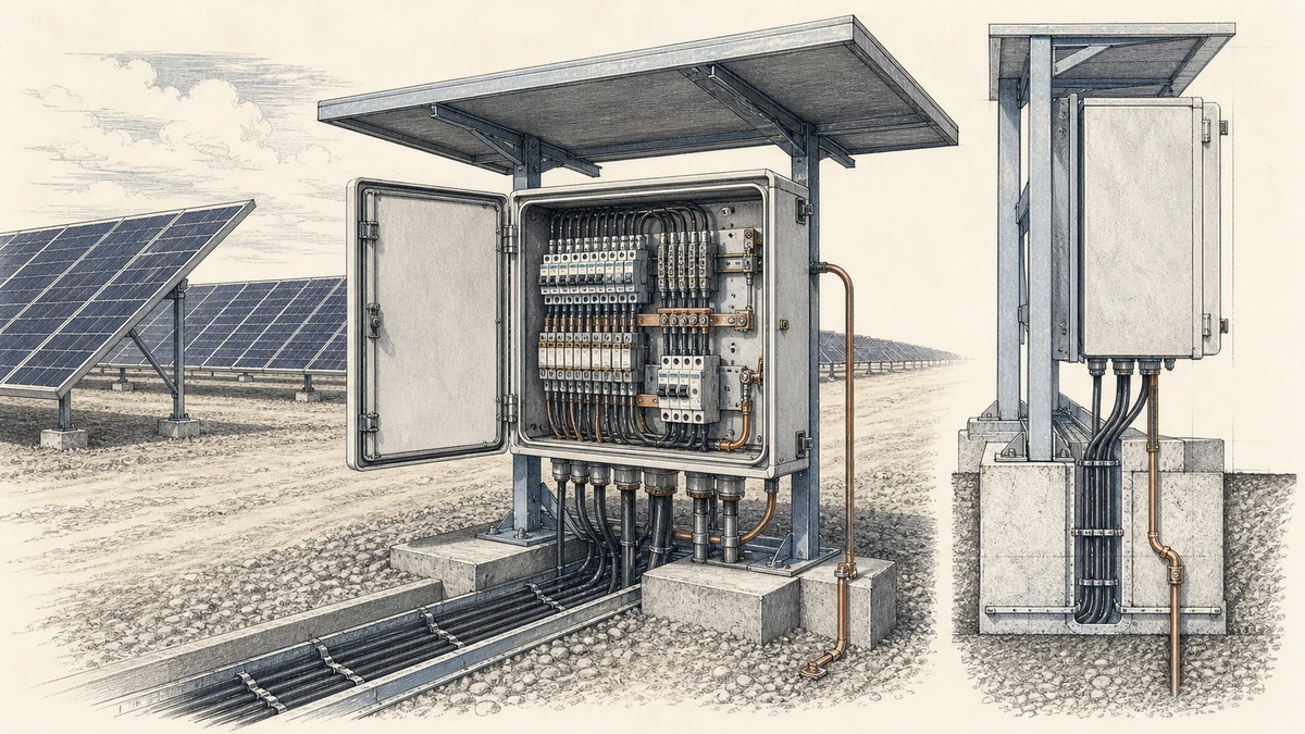
Insulation resistance testing checks whether PV string wiring, internal combiner conductors, and output cables are adequately insulated from earth and from opposite polarity conductors.
Before applying test voltage:
Insulation and dielectric-strength testing must only be performed by qualified personnel. Applying the wrong test voltage or testing through sensitive electronics can cause equipment damage.
Use the project-approved test method. Where permitted, strings may be tested individually before connection to the common bus. Record the test voltage and measured insulation resistance.
| String ID | Test voltage | Positive to PE | Negative to PE | Positive to negative | Result |
|—|—:|—:|—:|—:|—|
| String 1 | | | | | Pass / Fail |
| String 2 | | | | | Pass / Fail |
| String 3 | | | | | Pass / Fail |
| String 4 | | | | | Pass / Fail |
| String 5 | | | | | Pass / Fail |
| String 6 | | | | | Pass / Fail |
| String 7 | | | | | Pass / Fail |
| String 8 | | | | | Pass / Fail |
Acceptance criteria should follow the project specification, the applicable PV commissioning standard, and the equipment manufacturer’s instructions. Any unusually low or unstable reading should be investigated before energization.
After internal checks are complete and sensitive devices are protected or disconnected as required, test the outgoing DC circuit.
| Test item | Test voltage | Measured insulation resistance | Result |
|—|—:|—:|—|
| Output positive to PE | | | Pass / Fail |
| Output negative to PE | | | Pass / Fail |
| Output positive to output negative | | | Pass / Fail |
| Output cable to downstream disconnect | | | Pass / Fail |
If the reading is below the required limit, inspect for moisture, damaged cable insulation, incorrectly terminated conductors, contamination, crushed glands, or connected equipment that should have been isolated.
After insulation, continuity, and polarity tests are complete, restore the PV combiner box to its normal operating configuration according to the approved switching sequence.
| Item | Verification | Result |
|—|—|—|
| String fuses | Correct rating, installed in correct holders | Pass / Fail |
| Spare fuse holders | Empty or configured as specified | Pass / Fail |
| SPD | Status indicator normal after reconnection | Pass / Fail |
| DC switch-disconnector | Operates smoothly and locks where required | Pass / Fail |
| Monitoring CTs or sensors | Correct direction and channel assignment | Pass / Fail |
| Communication wiring | Secure and labeled | Pass / Fail |
Once the combiner box is safely energized under suitable irradiance, verify operating values.
| Measurement | Expected result | Measured value | Result |
|—|—|—:|—|
| Each string current | Similar for matched strings under similar irradiance | | Pass / Fail |
| Output current | Approximately sum of active string currents | | Pass / Fail |
| Output voltage | Within inverter MPPT input range | | Pass / Fail |
| Abnormal heating | No hot terminals or components | | Pass / Fail |
| Abnormal sound or smell | None | | Pass / Fail |
String currents may vary due to shading, module mismatch, soiling, orientation, or irradiance changes. Record site conditions so future maintenance teams can interpret the data correctly.
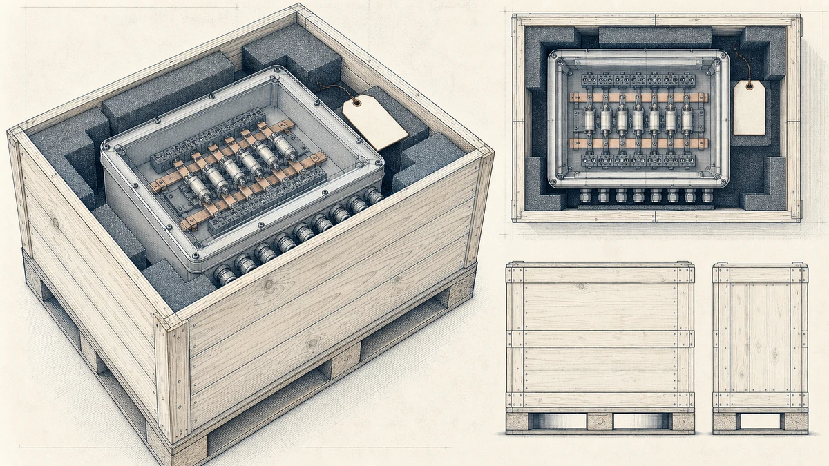
The PV combiner box should not be released for operation until all required inspection and test items are complete, nonconformities are corrected, and documentation is signed.
| Acceptance item | Status |
|—|—|
| Visual inspection completed | Pass / Fail |
| Terminal torque verified | Pass / Fail |
| PE continuity confirmed | Pass / Fail |
| String continuity confirmed | Pass / Fail |
| String polarity confirmed | Pass / Fail |
| Output polarity confirmed | Pass / Fail |
| String insulation resistance passed | Pass / Fail |
| Output insulation resistance passed | Pass / Fail |
| Voc within equipment voltage limit | Pass / Fail |
| Fuses and SPDs verified | Pass / Fail |
| Final operating voltage recorded | Pass / Fail |
| Final operating current recorded | Pass / Fail |
| Defects corrected and retested | Pass / Fail |
| Ready for energization | Yes / No |
| Sign-off | Record |
|—|—|
| Tested by | |
| Company | |
| Signature | |
| Date | |
| Reviewed by | |
| Signature | |
| Date | |
A reversed string is one of the most serious findings during a pv combiner box commissioning test. It may appear as a negative voltage reading when the multimeter probes are placed on the marked positive and negative terminals. Correct the wiring, relabel if needed, and retest before closing fuse holders.
Low insulation resistance may be caused by damaged cable jackets, moisture inside connectors, poor gland sealing, contaminated terminals, or testing through connected equipment. Isolate the fault by testing strings one at a time and checking cable routes, connectors, and junction points.
If one string voltage differs significantly from similar strings, check the module count, wiring route, connector compatibility, shading condition, and string layout. Also confirm that the corrected maximum open-circuit voltage does not exceed the rated limit of the PV combiner box and downstream equipment.
Loose terminals can pass a basic voltage test but fail under load. Torque verification is essential for string inputs, output terminals, grounding terminals, SPD connections, and internal busbar connections.
A PV combiner box commissioning test normally includes visual inspection, label verification, fuse and SPD checks, terminal torque confirmation, protective earth continuity, string continuity, polarity verification, insulation resistance testing, open-circuit voltage confirmation, and final operating current checks.
Some SPDs, monitoring modules, communication circuits, power supplies, and inverter input electronics can be damaged by insulation or dielectric-strength test voltage. Qualified personnel should follow the equipment documentation and isolate sensitive devices before applying test voltage.
Measure each string and the combiner output with a DC-rated multimeter. The voltage should show the expected positive value when the positive probe is on the marked positive terminal and the negative probe is on the marked negative terminal. If the reading is negative or inconsistent with the string design, stop and correct the wiring before energization.