Dirección
304 North Cardinal
Dorchester Center, MA 02124
Horas de trabajo
De lunes a viernes: de 7.00 a 19.00 horas
Fin de semana: 10.00 A 17.00 HORAS
Dirección
304 North Cardinal
Dorchester Center, MA 02124
Horas de trabajo
De lunes a viernes: de 7.00 a 19.00 horas
Fin de semana: 10.00 A 17.00 HORAS

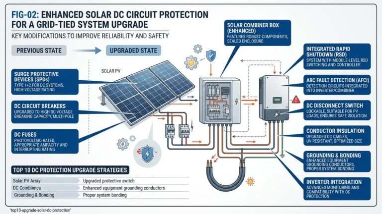
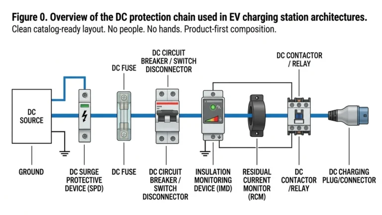
DC surge protection devices (DC SPDs) are a core safeguard in EV charging infrastructure, where transient overvoltages from lightning strikes, grid switching events, and cable inductance can exceed 6 kV on a 1000 VDC bus in under 1 microsecond. Selecting and installing the correct DC SPD helps prevent charger controller failures, protects vehicle communication circuits, and extends the life of power conversion equipment.
Transient risk in EV charging is shaped by the combination of high DC voltage, sensitive electronics, and exposed cable paths.
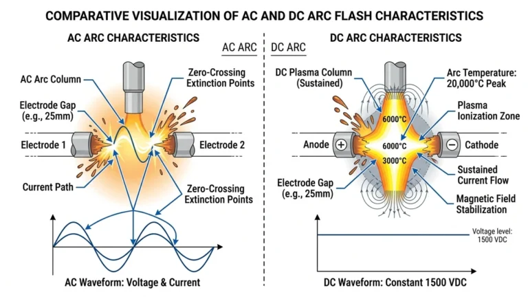
EV charging stations combine high DC bus voltages, typically 400–1000 VDC in fast-charging systems, with sensitive digital control electronics and long cable runs that can pick up induced surges. Unlike AC systems, DC buses do not benefit from natural zero crossings that help extinguish transient energy, so a single lightning-induced event or switching surge can damage IGBT modules, controller boards, and communication interfaces at the same time.
AC systems cross zero every 8–10 ms, which naturally limits conduction time during a transient event. DC charging buses carry continuous unidirectional current with no zero crossing, so overvoltages commonly reaching 2–4 kV in unprotected installations can sustain longer arc energy and drive deeper component damage. IEC 61643-11 classifies SPDs by maximum continuous operating voltage (Uc) and protection level (Up), and both must match the charging station’s DC architecture to work properly.
In a 120-unit DC fast-charging rollout across highway corridors in Zhejiang Province in 2023, stations without properly rated DC SPDs reported IGBT failure rates three times higher than protected units during the summer thunderstorm season. After retrofit with Type 2 DC SPDs rated at Uc ≥ 1000 V and Up ≤ 2.5 kV, engineers recorded a 34% reduction in controller board replacements over 18 months and roughly 60% less unplanned downtime in the following six months. That result tracks with IEC guidance that the SPD’s Up should remain below the equipment’s impulse withstand level.
Lightning is only part of the threat profile. Load switching inside the charger cabinet, disturbances passing through the AC/DC converter, and cable inductance during rapid current interruption can all generate transients in the 500 V to 2 kV range. A Disyuntor de CC manages overcurrent and short-circuit faults, but it does not clamp sub-millisecond voltage spikes, which is the specific job of a DC SPD. For formal SPD background and test context, see the IEC overview: https://www.iec.ch
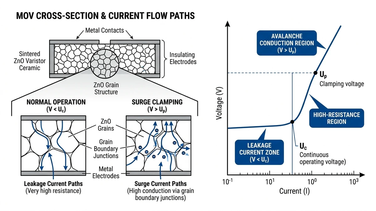
A DC SPD for EV charging infrastructure typically uses metal oxide varistor (MOV) technology to clamp transient overvoltages before they reach sensitive power electronics. DC-specific design must account for the absence of a natural current zero crossing, which changes how the device behaves after the surge is diverted.
An MOV is a voltage-dependent resistor made from sintered zinc oxide granules with additives at the grain boundaries. Under normal operating voltage, those junctions maintain high resistance, often above 1 MΩ, so leakage current remains very low. When a transient exceeds the varistor’s clamping threshold, the grain boundaries enter avalanche conduction, resistance drops sharply within nanoseconds, and surge current is diverted away from the protected load into the SPD discharge path.
The clamping voltage Up is defined under a standard 8/20 μs impulse waveform per IEC 61643-11, and for 1000 VDC EV charging bus applications, Up typically falls in the range of 2.5–4.0 kV. The continuous operating voltage Uc must be ≥ 1.1 × the maximum DC bus voltage to prevent thermal runaway from sustained leakage current.
In AC systems, the waveform crosses zero 100–120 times per second, helping extinguish follow current through the SPD. DC has no such zero crossing. Once an MOV begins conducting, current from the DC bus can continue flowing and create thermal runaway unless the SPD has sufficient energy absorption capability and a coordinated backup protective device to interrupt the follow current.
In a 120 kW DC fast charger installation in Zhejiang Province in 2023, engineers found that SPDs without DC-rated disconnectors failed within weeks because follow current was sustained at 800 VDC, a failure mode that AC-rated SPDs are not built to survive.
MOV capacity degrades with repeated surge events. IEC 61643-11 uses impulse current and nominal discharge current ratings to classify SPD capability, with Type 1 devices handling 10/350 µs lightning-current impulses and Type 2 devices typically rated by In on the 8/20 µs waveform. In EV charging environments with frequent switching transients from converter stages, selecting an MOV with In of at least 20 kA at charger inputs provides useful life margin. More on the trade-offs between device technologies appears in this DC SPD technology comparison.
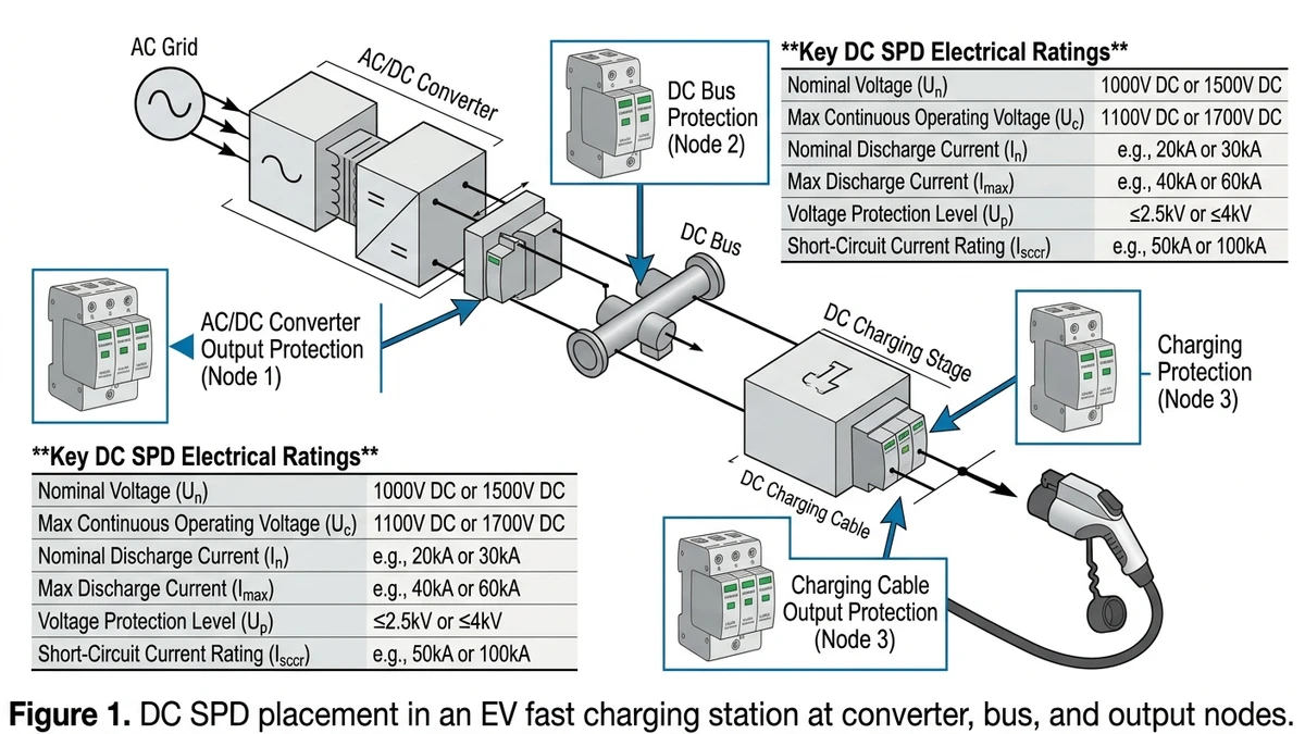
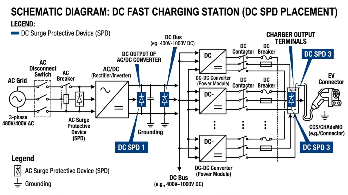
DC SPD placement depends on charger topology, bus voltage, and the length of exposed DC cable runs. A device that is correctly rated but placed at the wrong point in the circuit may offer little practical protection.
These chargers convert AC to DC internally, so the DC SPD is typically installed inside the EVSE enclosure to protect the internal rectifier and control electronics. The DC bus usually operates between 200 and 450 VDC. A Type 2 SPD with Up at or below 1.5 kV is generally suitable when installed between the rectifier output and the charging connector interface.
The charger uses an external or cabinet-integrated power conversion stage feeding a 500–1000 VDC output bus directly to the vehicle. SPD placement is especially important at the AC/DC converter output and at the DC distribution busbar before cable branching. In one 120 kW highway installation in Zhejiang Province, SPDs fitted only on the AC input did not prevent controller board damage caused by DC-side transients.
High-power charging stations operating at 800–1000 VDC usually need coordinated protection at three points: transformer secondary or main supply interface, central DC busbar, and individual charging outlets. The surge protection device series should be selected with node-specific Up values in mind, since the acceptable residual voltage can vary by equipment location and cable run length. Pairing SPDs with properly rated protective devices also ensures surge clamping and fault isolation work together.
[Expert Insight]
– Keep the SPD physically close to the busbar or protected terminal; long connection leads add inductive voltage and raise the effective residual seen by the load.
– On multi-bay chargers, protect the shared DC bus and the outlet branches separately if cable lengths or exposure differ between bays.
– If a charger has repeated board failures despite AC-side protection, inspect the DC side first; many field issues originate at the bus or output cables, not the service entrance.
Type 1 and Type 2 DC SPDs serve different threat levels and should not be treated as interchangeable. Type 1 devices are intended for partial lightning current duty at exposed service entrances, while Type 2 devices handle switching surges and induced transients farther downstream.
Charging station exposure depends mainly on whether the site has an external lightning protection system, how long and exposed the DC cable runs are, and the local thunderstorm density. A rooftop fast-charging hub in a high-keraunic region such as Guangdong may require Type 1 protection at the main DC distribution point, while an underground parking garage with shielded cable runs under 30 m can often rely on Type 2 devices alone.
For mixed conditions, a Type 1+2 combined SPD at the main panel plus Type 2 devices at charger cabinets is the standard cascade under IEC 60364-5-53. The chosen device for a 1000 VDC system should also have Uc of at least 1100 VDC to avoid operating too close to the normal bus voltage.
| Parámetro | Type 1 DC SPD | Type 2 DC SPD |
|---|---|---|
| Impulse current rating | Iimp ≥ 12.5 kA (10/350 µs) | In = 5–20 kA (8/20 µs) |
| Primary threat | Direct/partial lightning strike | Switching surges, induced transients |
| Typical installation point | Main DC service entrance, LPS-bonded panel | Charger cabinet, downstream distribution |
| IEC standard | IEC 61643-11 Class I | IEC 61643-11 Class II |
| Required when | External LPS present or exposed overhead lines | All EV DC installations as baseline protection |
| Protection level (Up) | ≤ 4 kV | ≤ 2.5 kV |
| Typical Uc (1000V systems) | ≥ 1100 VDC | ≥ 1100 VDC |
For more on how clamping technology affects real-world behavior in both classes, the DC SPD fundamentals guide explains MOV and GDT trade-offs. Upstream coordination with a properly rated Fusible CC is equally important so the backup path can clear follow current without unnecessary trips.
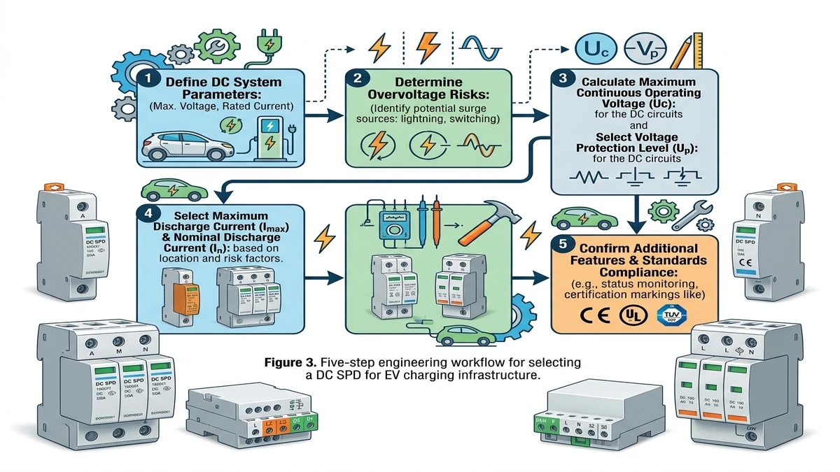
Identify the highest continuous DC voltage in the circuit being protected. A 150 kW fast charger may operate across a wide output range, while an upstream rectifier or storage-linked bus can reach 1500 VDC. The SPD’s Uc should equal or exceed the maximum system voltage, typically with 10–15% margin, because an undersized Uc will accelerate MOV aging.
Classify the site by exposure. Open parking lots, canopy structures, and highway rest stops face more severe lightning coupling than enclosed garages. For exposed sites, In of at least 20 kA on the 8/20 µs waveform is a practical baseline; lower-exposure indoor sites may use 10 kA where supported by the risk assessment. A 2023 highway corridor project in Shandong increased the specification to 40 kA Imax after one storm season damaged three unprotected chargers.
The SPD’s Up must stay below the impulse withstand level of the protected electronics. Many DC/DC converter modules are rated around 2.5 kV, so an SPD with lower residual voltage gives a more comfortable coordination margin. IEC 61643-31 provides relevant methodology for DC power systems.
Use the installation point and exposure to decide the SPD class:
– Type 1 for service entrances where direct or partial lightning current can couple in
– Type 2 for distribution boards and charger input terminals
– Type 1+2 combined for standalone fast-charging canopies or other exposed sites without separate staged protection
A DC SPD must be paired with a backup protective device, typically a DC MCB or fuse, rated for the prospective short-circuit current at the installation point. In commercial charging infrastructure, that can reach 10–25 kA. If the site operator uses centralized supervision, also confirm whether the SPD supports remote fault indication through a dry contact or communication interface compatible with the charger management system.
IEC 61643-11 installation practice puts real weight on bonding quality, lead length, and coordination with upstream protective devices.
Before adding SPDs to an existing DCFC cabinet, verify:
– Available cabinet space, including DIN rail depth and conductor bend radius
– Busbar rating, so the SPD discharge path does not exceed the busbar’s capability
– Total lead length, which should stay under 500 mm to limit inductive voltage rise
– Coordination with the existing disconnect so the upstream device can support the SPD’s short-circuit current rating
In a 2024 Zhejiang highway-corridor rollout, about 30% of retrofit cabinets exceeded 600 mm lead length and required busbar rework before the SPDs could be installed correctly.
New builds make it easier to avoid these compromises:
– Place the SPD as close as possible to the DC busbar entry point
– Use bonding conductors of at least 6 mm² copper where appropriate for the surge current duty
– Coordinate the backup fuse or DC MCB with the SPD manufacturer’s short-circuit rating
– Include status-monitor wiring if remote alarm reporting is required
– Maintain thermal clearance, especially in cabinets that can reach 60–70°C during peak charging periods
[Expert Insight]
– Measure actual lead length after routing, not just straight-line cabinet distance; bends and service loops often add enough length to spoil performance.
– In hot cabinets, mount the SPD away from the main heat plume of power modules and contactors to reduce long-term MOV stress.
– If remote indication is specified, test the alarm contact during commissioning; many monitoring issues come from control wiring errors rather than SPD faults.
| Estándar | Governing Body | Alcance | Key Parameters for EV Charging |
|---|---|---|---|
| IEC 61643-11 | IEC | DC SPD performance and testing | Up, Uc, impulse and discharge current ratings |
| IEC 61643-31 | IEC | SPDs for DC applications including relevant power-system methodology | DC voltage class, test method, discharge capability |
| IEC 61851-1 | IEC | EV conductive charging system requirements | Charging modes and system context |
| IEC 62305-1/-2 | IEC | Lightning protection risk assessment | Determines required protection class by risk zone |
| UL 1449 (5th Ed.) | UL | SPD performance for North American market | MCOV, nominal discharge current, SVR |
| GB/T 18802.12 | SAC | Chinese national equivalent framework for SPD application | Required for China-market EVSE projects |
| IEC 60364-7-722 | IEC | Electrical installations for EV supply equipment | Installation-side SPD placement requirements |
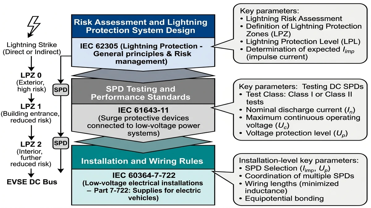
IEC 61643-11 remains the core device test standard because it governs clamping voltage, continuous operating voltage, and discharge-current performance. For fast chargers operating on 750–1000 VDC buses, Uc should be selected above the maximum bus voltage with a 10–15% margin. IEC 62305-2 supports the site risk assessment that determines whether Type 1 protection is needed at the service entrance, while IEC 60364-7-722 addresses EV supply equipment installation practice.
In a 2023 Zhejiang DC charging depot project, engineers specified Type 2 SPDs at Uc = 1000 VDC and In = 20 kA in line with project compliance requirements and system audit needs. For higher-exposure sites, Type 1 SPDs rated for partial lightning current at the entrance and Type 2 devices at the EVSE distribution board remain the standard layered approach.
A 150 kW charger in a coastal or high-lightning-density zone will often justify a Type 1+2 combined SPD rated for partial lightning current duty at the upstream point. In one 2023 highway corridor project in Zhejiang Province, stations without Type 1 protection saw repeated SPD replacements within 18 months; after switching to combined Type 1+2 units, repeat failures stopped through the next storm season.
If you’re specifying a new site or retrofitting an existing one, the surge protection device series includes options rated from 600 to 1500 VDC with tested Up values and discharge-current classes.
For many 800–1000 VDC fast chargers, engineers start with a Type 2 DC SPD having Uc above the maximum bus voltage and In around 20 kA for exposed sites. Final sizing should follow the site’s lightning risk, cable layout, and equipment insulation level.
It is usually installed at the main DC bus or converter output, and higher-power systems may also need protection at branch outputs or dispenser lines. The best location is the point with the shortest, lowest-inductance connection to the protected node.
No. AC SPDs are not designed to handle sustained DC follow current and can fail dangerously when used on a high-voltage DC circuit.
Many installations use Type 2 as the baseline at charger cabinets, while exposed sites with external lightning protection or high strike risk often need Type 1 or Type 1+2 at the upstream distribution point. The correct answer depends on site exposure and the protection cascade.
It is critical because extra conductor length adds inductive voltage during a surge and increases the residual voltage seen by the protected electronics. Even a correctly rated SPD can underperform if the wiring path is too long.
IEC 61643-11 is the main device standard, IEC 62305 supports lightning risk assessment, and IEC 60364-7-722 addresses EV installation practice. Local projects may also require UL or GB/T compliance depending on market and jurisdiction.
Compare the SPD’s residual voltage to the impulse withstand rating of the charger’s power electronics and maintain a coordination margin. The SPD should clamp below the level that the converter modules, control boards, and communication interfaces can tolerate.