Dirección
304 North Cardinal
Dorchester Center, MA 02124
Horas de trabajo
De lunes a viernes: de 7.00 a 19.00 horas
Fin de semana: 10.00 A 17.00 HORAS
Dirección
304 North Cardinal
Dorchester Center, MA 02124
Horas de trabajo
De lunes a viernes: de 7.00 a 19.00 horas
Fin de semana: 10.00 A 17.00 HORAS

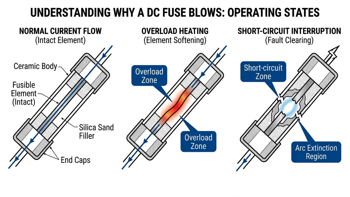
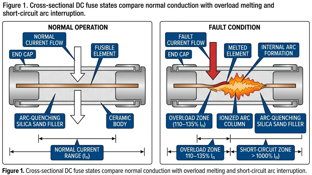
A DC fuse blows when current through the circuit exceeds the fuse’s rated amperage long enough to melt the fusible element. In DC systems, this happens under two conditions: a sustained overload above 110–135% of rated current, or a short-circuit fault delivering current many times the rated value within milliseconds.
DC fuse failure traces back to one of two electrical events.
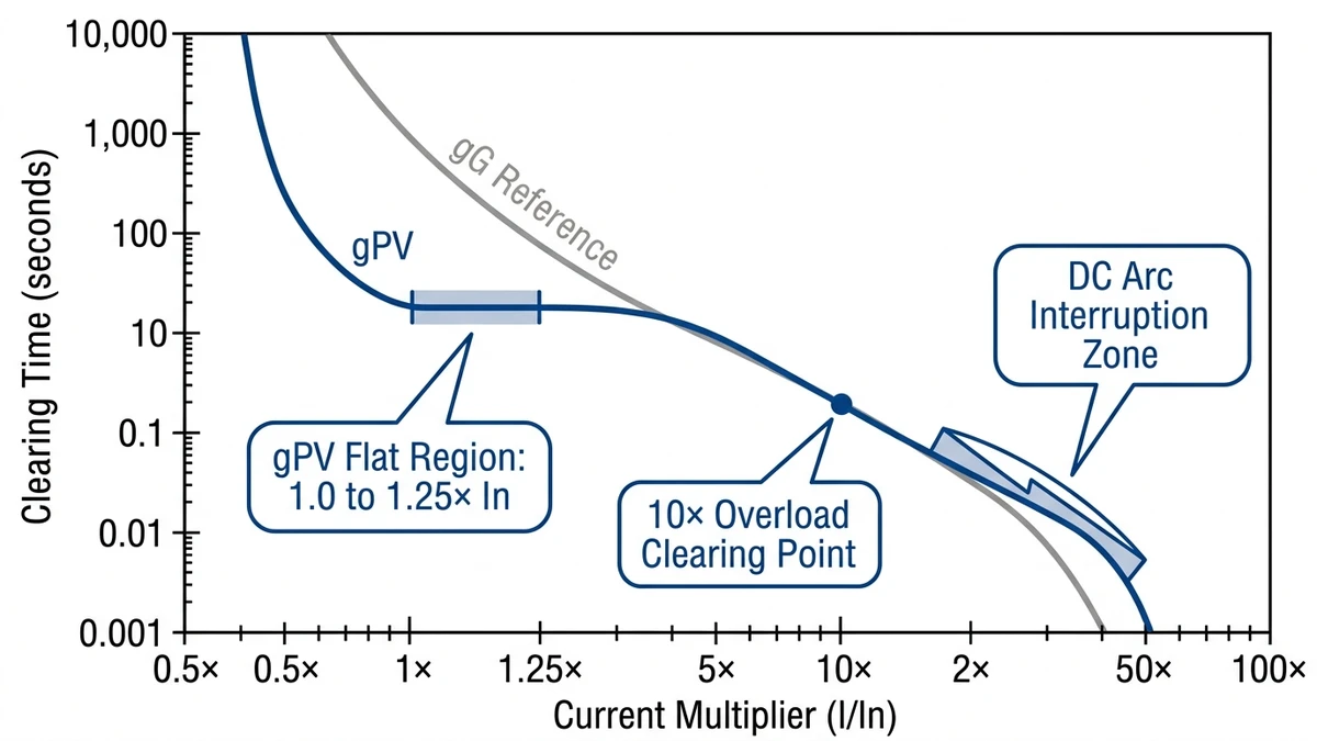
An overload occurs when the circuit draws more current than the fuse is rated for — typically 110–135% of In (rated current) sustained over seconds to minutes. The fusible element heats progressively until it reaches its melting point. In photovoltaic string circuits, this often results from partial shading mismatches, reverse current from adjacent strings, or undersized wiring that increases resistive losses and effective load. IEC 60269-6, which governs gPV fuses for solar applications, defines the time-current characteristics that determine how long a fuse tolerates a given overload before opening.
A short-circuit delivers prospective fault current that can reach 10–40 kA in utility-scale DC systems, depending on source impedance. The fusible element vaporizes in under 10 ms, interrupting the fault before downstream components sustain damage. Unlike AC systems, DC arcs have no natural current zero crossing, so the fuse must also extinguish the resulting arc — a critical design requirement that separates DC-rated fuses from general-purpose types.
In a 35 MW ground-mount PV installation in Hebei Province (2023), field engineers identified repeated fuse failures in three combiner boxes traced to reverse current exceeding 1.3× In during morning irradiance transitions — a classic overload scenario, not a short circuit.
For a deeper look at how fuse ratings map to system protection needs, the DC fuse selection guide covers rated voltage, breaking capacity, and gPV classification in detail.
Knowing that a fuse has blown is only the first step; the failure pattern usually tells you whether the problem was overload, fatigue, or arc interruption stress.
Thermal overload occurs when sustained current exceeds the fuse’s rated ampacity without triggering fast rupture. The element heats progressively — resistive heating follows I²t accumulation — until the lowest cross-section point melts. IEC 60269-6 defines the conventional non-fusing current at 1.25× In and the minimum fusing current at 1.6× In for gPV applications. In practice, a fuse operating continuously at 110–120% of rated current may survive for hours before element degradation becomes irreversible. The failure signature is a clean, localized melt point near the element’s narrowest section.
Repeated thermal cycling — common in solar string circuits that ramp from near-zero to full Isc daily — causes cumulative metallurgical fatigue in the silver or copper element. Each expansion-contraction cycle introduces micro-stress at grain boundaries. In a 60 MW ground-mount installation in Gansu Province (2023), maintenance crews found a statistically elevated rate of nuisance fuse failures on east-facing strings, where thermal cycling amplitude was highest due to rapid morning irradiance ramp-up. This failure mode produces no visible overcurrent event; the element fractures under normal operating current. Per IEC 60269-1, fuse elements must withstand 100 thermal cycles between 20% and 100% rated current without degradation — a threshold that real-world PV cycling can approach within 3–5 years.
This is the most dangerous mode. When a fuse element begins to melt under a high-magnitude fault, the gap must extinguish a DC arc before the enclosure fails. In 1000–1500 VDC string circuits, an undersized or incorrect fuse — such as an AC-rated fuse installed in a DC application — may fail to interrupt the arc entirely, resulting in enclosure rupture or fire. Properly rated Fusibles gPV include arc-quenching filler and are voltage-rated specifically for DC. That distinction is why substituting AC fuses in DC circuits, even at matching ampere ratings, is unsafe and noncompliant in most installations.
[Expert Insight]
– A bright, clean break usually points to a fast high-current event; darkening, blistering, or body discoloration points more often to heat buildup over time.
– Compare failed fuses from neighboring strings: one isolated failure suggests a local issue, while similar damage patterns across multiple holders often indicate a systemwide sizing or temperature problem.
– If the holder looks more damaged than the fuse link, suspect contact resistance before you suspect the element itself.
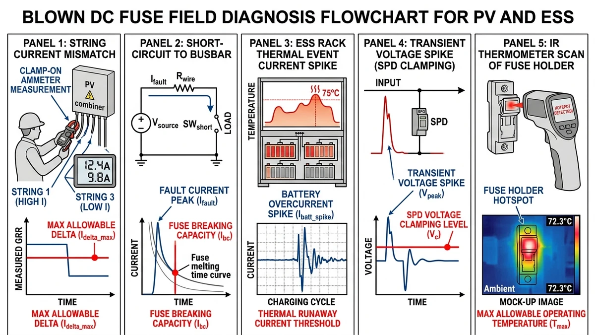
Most repeat fuse issues in PV and ESS sites can be narrowed to a short list of field conditions you can verify with standard test instruments.
When shading, soiling, or cell degradation reduces output on one string, reverse current from adjacent strings can push a fuse beyond its rated continuous current. IEC 60269-6 defines the overload zone as 1.25× to 1.6× rated current — a range where thermal damage accumulates slowly before the fuse opens. Check string Isc values at the combiner box; a mismatch greater than 10% between strings warrants investigation.
A bolted fault at the DC busbar can produce fault currents well above the fuse’s rated breaking capacity. In a typical 1500 V string architecture, prospective short-circuit current at the caja combinadora can reach 15–25 kA depending on parallel string count. If the installed fuse carries a breaking capacity below that value, it will rupture destructively rather than interrupt cleanly.
In lithium-ion ESS racks, a cell-level thermal event drives bus voltage and current simultaneously. A 30 MWh ESS project in Zhejiang Province (2023) recorded pre-fault current spikes of 3× rated DC bus current for 200–400 ms before string fuses actuated — well within the gPV fuse’s I²t clearing window, but only when fuses were correctly sized to the module’s short-circuit rating. Undersized fuses had already failed on nuisance trips during normal charge cycles.
Switching transients and indirect lightning strikes inject high-frequency voltage spikes that stress fuse elements beyond their rated DC voltage. IEC 60269-6 specifies a rated voltage of 1000 VDC or 1500 VDC for gPV fuses — operating above that threshold without a coordinated surge protection device accelerates element fatigue. Measure peak transient voltage with a power quality analyzer; readings above 1.1× rated voltage indicate inadequate surge coordination.
Loose or corroded fuse holders create localized resistance that generates heat independent of load current. An IR thermometer reading more than 15°C above ambient at the fuse holder end-cap — under normal operating load — points to contact resistance as the failure driver rather than overcurrent. This is a common finding in outdoor PV fuse holders exposed to humidity cycling. Torque connections to manufacturer specification and inspect for oxidation on the contact surfaces.
A replacement fuse only solves the problem if the original failure mode has been identified and corrected first.
Disconnect the DC source before touching anything. For PV systems, open the string disconnect and wait for capacitive voltage to drop below 50 VDC. Verify with a calibrated multimeter set to the DC voltage range.
Remove the fuse and examine the element. A clean, sharp break typically indicates a short-circuit fault. A discolored or melted body with blackened end caps points to sustained overload or poor thermal conditions.
Set your multimeter to resistance mode. A healthy fuse reads near 0 Ω. A blown fuse reads OL.
Clamp-meter the circuit under normal load and compare the reading against the fuse’s rated current. If measured current exceeds 1.25× the fuse rating continuously, the fuse is undersized for the load rather than defective.
Confirm the fuse voltage rating matches or exceeds the open-circuit string voltage (Voc). In a 1500 VDC string architecture, using a fuse rated for only 1000 VDC creates an arc interruption risk even if the current rating appears correct. See the DC fuse selection guide for rating cross-reference.
A loose fuse holder contact adds resistance, generating localized heat that degrades the fuse element over time. Check contact pressure and look for oxidation or heat discoloration. The PV fuse holder selection guide covers useful contact resistance checkpoints.
Install a correctly rated replacement matched on both current and DC voltage. In a 30 MW ground-mount installation in Hebei Province (2023), maintenance crews reduced repeat fuse failures by identifying undersized string fuses across 18 combiner boxes before replacing them. After replacement, monitor the circuit for at least 15 minutes under full load before closing the enclosure.
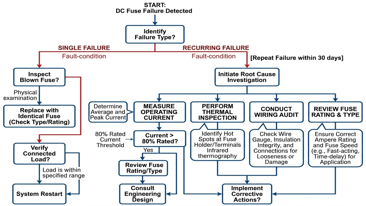
The pattern of failure matters: one isolated event may justify replacement, but repeat operation in the same position almost always signals a circuit problem.
One blown fuse is not automatically a red flag. Transient overcurrents from capacitive inrush, switching surges, or a brief ground fault can rupture a fuse without leaving a persistent fault behind. Before replacing, confirm the measured load current sits below 80% of the fuse’s rated current — the common continuous-load threshold under IEC 60269-1. If it does, install a same-rated replacement and monitor for 72 hours. No recurrence usually means the event was isolated.
For gPV string fuses in solar arrays, also verify the fuse’s voltage rating matches the open-circuit string voltage at minimum temperature, which can exceed nominal Voc by 10–15% in cold climates.
If the same fuse position blows twice or more, replacement alone is a safety risk. Use this field triage:
In a 12 MW ground-mount installation in Hebei Province (2023), recurring fuse failures across three combiner boxes were traced to undersized cable terminations generating localized resistance heating — not overcurrent. Replacing fuses without investigating had masked the fault for over six weeks.
[Expert Insight]
– If the replacement fails in the same holder but the neighboring holder runs cool, swap only after checking torque, spring pressure, and terminal condition at that specific location.
– Track failures by date, ambient temperature, and irradiance level; recurring events at the same time of day often reveal mismatch or thermal expansion issues.
– Never “solve” nuisance trips by increasing fuse amp rating before confirming conductor ampacity, holder rating, and required protection study.
When more than one protective device sits in series, proper coordination determines whether a fault stays local or takes down a larger section of the DC system.
A properly coordinated DC protection scheme operates in tiers: string-level fuses clear first, then combiner-level fuses, then main DC fuses. If the string fuse fails to clear before the combiner fuse responds, you lose an entire combiner’s worth of generation — or worse, damage upstream equipment. In a 60 MW ground-mount installation in Hebei Province (2023), poor selectivity between 15 A string fuses and 100 A combiner fuses caused three combiners to go offline during a single string fault because the I²t ratings had never been verified against each other.
Selectivity in DC fuse protection is governed by I²t coordination — the relationship between a fuse’s let-through energy and the upstream fuse’s minimum melting energy. For the downstream fuse to clear first, its total clearing I²t must be lower than the pre-arcing I²t of the upstream fuse at the same prospective fault current.
The coordination condition is:
I²tclearing (downstream) < I²tpre-arcing (upstream)
Typical string-level gPV fuses carry a clearing I²t in the range of 500–5000 A²s at rated voltage, while combiner-level fuses may have pre-arcing I²t values starting at 8000–50,000 A²s — leaving a coordination margin that must be verified, not assumed.
IEC 60269-6 requires manufacturers to publish both pre-arcing and total clearing I²t values across the current range. When troubleshooting nuisance trips or cascade failures, compare those curves at the actual prospective fault current for your system voltage, not just at rated current.
If you’re selecting or replacing fuses in a string protection circuit, the gPV fuse series provides published I²t data suitable for coordination analysis. For broader system architecture, the DC fuse selection guide covers rating methodology in detail. When coordination cannot be achieved with fuses alone, pairing them with a DC MCB at the combiner level adds adjustable trip characteristics that fuses cannot provide.
Once the failure cause is confirmed, replacement selection comes down to matching electrical duty, physical fit, and application category.
| Parámetro | Typical Range / Requirement | Notas |
|---|---|---|
| Rated Voltage (Vn) | 1000 VDC or 1500 VDC | Must equal or exceed system open-circuit voltage |
| Rated Current (In) | 1.0 × Isc to 1.25 × Isc | Per IEC 60269-6 string protection guidance |
| Breaking Capacity (Icu) | ≥ 10 kA at rated DC voltage | Verify against prospective fault current at combiner |
| Physical Size | 10×38 mm or 14×85 mm (most common) | Must match holder contact spacing exactly |
| Temperatura de funcionamiento | −40 °C to +85 °C | Derate In if ambient exceeds 40 °C |
The utilization category printed on a fuse body defines the fuse’s time-current characteristic for a specific application. For photovoltaic DC circuits, IEC 60269-6 governs the gPV category, which is engineered for sustained PV short-circuit current, high DC voltage, and prolonged arc energy.
A gPV fuse rated at 15 A / 1000 VDC will carry 1.25× rated current continuously without opening while clearing a 10× overload within seconds. Substituting a general-purpose gG or gL fuse is a common field error; those categories are calibrated for AC mains and may nuisance-trip under normal PV conditions or fail to clear a DC arc reliably.
For a deeper comparison of physical formats and holder compatibility, the PV fuse size selection guide covers 10×38 mm versus 14×85 mm trade-offs. When sourcing replacements, verify the full gPV fuse datasheet confirms IEC 60269-6 compliance at the system’s actual open-circuit voltage.
The most reliable way to avoid repeat failures is to make sure the replacement fuse actually matches the system it is protecting.
Before selecting a replacement or upgrade, confirm these values against your system specs:
Standard AC fuses are not rated for DC arc interruption and will fail under PV fault conditions. For solar string protection, gPV fuses are the correct class — they are designed to interrupt DC arcs at 1000–1500 VDC and tested under IEC 60269-6. Our DC fuse selection guide covers size-to-application matching in more detail.
If your system requires frequent isolation, bidirectional protection, or remote switching, a Disyuntor de CC may be more appropriate than a fuse. For string-level overcurrent protection combined with disconnect capability, explore DC MCB options as an alternative.
If you still need help matching fuse voltage class, current load, and fault current exposure, contact our technical team for sizing support.
Repeated fuse operation usually indicates an unresolved issue such as overload, reverse current, poor holder contact, or an incorrect fuse rating. Replacing the fuse without testing the circuit often leads to another failure.
No. Matching amperage alone is not enough because DC fuses are designed to interrupt sustained DC arcs at specific voltage levels.
A fast fault often leaves a sharp break in the element, while overload tends to leave more heat staining, discoloration, or damage around the fuse body and holder. You still need current and voltage checks to confirm the cause.
Verify the fuse’s voltage rating, current rating, breaking capacity, physical size, and utilization category against the actual system conditions. Also inspect the holder and wiring so you do not install a new fuse into a damaged connection.
Excess heat at the holder often comes from loose terminals, corrosion, weak contact pressure, or surface oxidation rather than excessive circuit current. Thermal scanning is one of the fastest ways to spot this condition.
If the same position fails more than once, if multiple fuses fail in one area, or if the holder shows heat damage, stop replacing parts and begin fault tracing. Repeat failures almost always point to a wiring, coordination, or sizing problem.
Use a gPV fuse with a voltage rating at or above the string Voc, a current rating suited to the string current, and a breaking capacity above the available fault current. The fuse also has to match the holder size and the site’s temperature conditions.


