Adresse
304 North Cardinal
St. Dorchester Center, MA 02124
Heures de travail
Du lundi au vendredi : de 7h00 à 19h00
Le week-end : 10H00 - 17H00
Adresse
304 North Cardinal
St. Dorchester Center, MA 02124
Heures de travail
Du lundi au vendredi : de 7h00 à 19h00
Le week-end : 10H00 - 17H00

Outdoor electrical junction boxes provide critical connection points in solar PV systems where multiple circuits converge, branch, or transition between different cable types. Unlike simple pass-through conduits, junction boxes house wire splices, terminal blocks, and branch connections that must remain accessible for inspection while protected from weather exposure. This comprehensive guide explains everything professional installers and electrical engineers need to know about selecting, sizing, installing, and maintaining outdoor electrical junction boxes for solar applications.
Outdoor electrical junction boxes serve distinct purposes from other electrical enclosures in solar PV systems. While distribution boxes house protective devices like circuit breakers and fuses, junction boxes primarily provide protected spaces for wire connections and cable transitions.
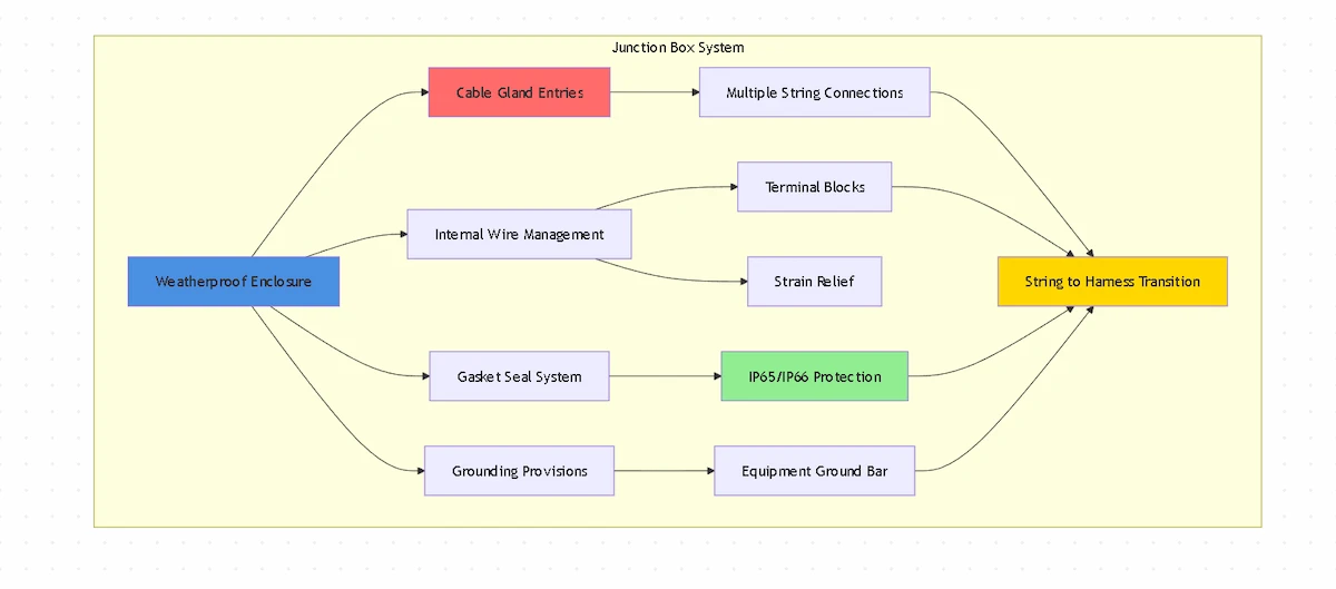
A junction box allows installers to connect multiple conductor runs without creating vulnerable splice points. In solar installations, junction boxes facilitate string-to-harness transitions, enable branch circuit connections, provide pull points for long conduit runs, and create accessible splice locations for future system modifications. These functions require adequate internal volume for cable bending radius and proper wire management.
💡 Aperçu clé : Junction boxes differ from combiner boxes in function and code requirements. Combiner boxes house overcurrent protection devices and require specific ratings for solar applications. Junction boxes contain only splices and connections, following general wiring method rules under Article 314 du NEC.
Weather protection requirements for outdoor junction boxes match other exterior electrical enclosures. The box must achieve appropriate IP rating for the installation environment, typically IP65 minimum for rooftop solar installations. However, junction boxes face additional challenges because multiple cable entries increase potential moisture ingress points compared to equipment enclosures with fewer penetrations.
Outdoor junction boxes fall into several categories based on construction method, entry configuration, and mounting style. Understanding these variations helps specify appropriate boxes for different solar PV applications.
Molded plastic junction boxes use injection-molded polycarbonate or ABS construction with integrated mounting flanges and pre-formed knockout locations. These boxes provide excellent weather resistance, UV stability, and corrosion immunity. Molded designs typically include internal cable management features like strain relief points and wire retention clips. The seamless construction minimizes potential leak paths compared to assembled metal boxes.
Cast metal junction boxes offer maximum physical protection and EMI shielding for sensitive applications. Aluminum construction provides lighter weight than steel while maintaining strength. However, metal boxes require careful grounding and may require supplemental sealing at joints between body and cover. Metal boxes excel where impact resistance, vandal protection, or electromagnetic compatibility become critical requirements.
Assembled plastic boxes use separate base and cover components sealed with gaskets. This construction allows larger sizes than practical for single-piece molding. Assembled boxes offer flexibility in knockout configuration since penetrations are field-installed rather than pre-formed. However, the body-to-cover joint creates additional sealing challenges compared to molded one-piece bodies with gasketed covers.
Pull boxes represent specialized junction boxes designed primarily as conduit pull points rather than permanent splice locations. These boxes feature large internal volume relative to entry sizes, simplifying wire pulling through long conduit runs. While pull boxes can house splices, their primary function facilitates cable installation. Solar installations frequently use pull boxes at conduit transitions between roof and interior spaces.
⚠️ Important : “Junction box” and “pull box” have specific meanings in NEC Article 314. Junction boxes house splices and taps, while pull boxes facilitate conductor pulling. Sizing calculations differ between types. Verify which designation applies to your application before calculating minimum dimensions.
Proper junction box sizing ensures adequate space for conductors, splices, and cable bending while meeting NEC requirements. Undersized boxes create installation difficulties and code violations, while oversized boxes waste space and money.
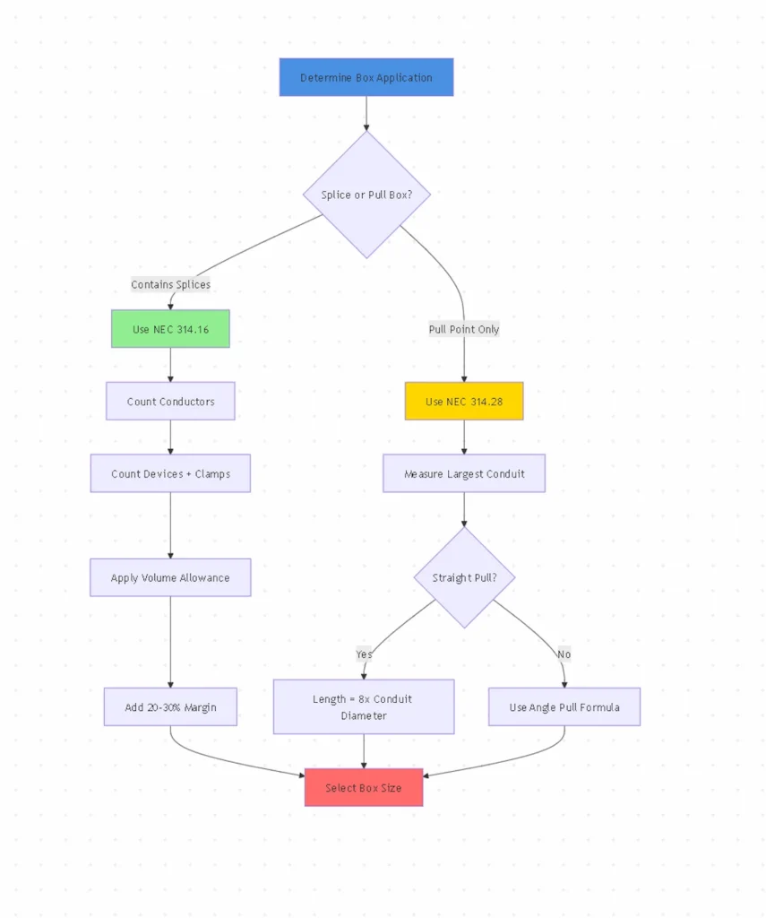
NEC Article 314.28 specifies minimum dimensions for pull and junction boxes. For straight pulls (conductors pass through without splicing), the box length must be at least eight times the trade diameter of the largest raceway. For angle pulls or U-pulls where conductors enter and exit through different walls, calculations become more complex based on raceway sizes and orientations.
When boxes contain splices rather than straight pulls, NEC Article 314.16 governs sizing based on conductor count and size. Each conductor entering the box counts once toward fill calculation. Each wire connector (wire nut) or device counts as one conductor volume. Clamps internal to the box count as one conductor. Grounding conductors count as one conductor regardless of quantity.
Conductor volume allowances vary by wire size per NEC Table 314.16(B). For example, 12 AWG conductors require 2.25 cubic inches each, while 10 AWG requires 2.5 cubic inches. Calculate total required volume by multiplying conductor count (including devices and clamps) by the allowance for the largest conductor size present. Select boxes with volume meeting or exceeding this calculation.
🎯 Pro Tip : Add 20-30% extra volume beyond minimum NEC requirements for solar junction boxes. Future system expansions often require additional connections. Extra space also simplifies initial installation by providing working room for wire management.
Scénario : Combining four 10 AWG solar strings into one harness
Calcul :
| Wire Size (AWG) | Volume par conducteur | Typical Solar Application | Example Box Size |
|---|---|---|---|
| 14 AWG | 2,0 pouces cubes | Small residential monitoring | 4″×4″×2″ |
| 12 AWG | 2,25 pouces cubes | Residential string connections | 6″×6″×3″ |
| 10 AWG | 2,5 pouces cubes | Standard solar strings | 8″×8″×4″ |
| 8 AWG | 3,0 pouces cubes | High-power strings | 10″×10″×4″ |
| 6 AWG | 5,0 pouces cubes | Connexions du faisceau commercial | 12″×12″×6″ |
Les matériaux des boîtes de jonction doivent résister à une exposition continue à l'extérieur tout en maintenant l'intégrité structurelle et l'étanchéité. Le choix des matériaux influe considérablement sur la durée de vie, en particulier dans les environnements difficiles des installations solaires.
Polycarbonate stabilisé aux UV offre un équilibre optimal de propriétés pour les boîtes de jonction solaires. Ce matériau conserve sa résistance aux chocs et sa stabilité dimensionnelle de -40°C à +120°C tout en résistant à la dégradation par les UV pendant plus de 10 ans. Le polycarbonate de qualité incorpore une stabilisation UV8 (résistance à l'exposition aux UV pendant plus de 8 000 heures, conformément aux normes ASTM). Le matériau résiste naturellement au jaunissement et à la fragilité, même en cas d'exposition intense au soleil sur les toits.
Polyester renforcé de fibres de verre (FRP) offre une résistance chimique et une ignifugation supérieures pour les environnements industriels. Le PRF maintient un excellent rapport résistance/poids et une stabilité dimensionnelle à des températures extrêmes. Cependant, le PRF coûte beaucoup plus cher que le polycarbonate tout en offrant des performances extérieures similaires pour la plupart des applications solaires. Le PRV est principalement spécifié en cas d'exposition aux produits chimiques ou d'exigences strictes en matière de propagation de la flamme.
Aluminium moulé sous pression offre une sécurité physique maximale et un blindage électromagnétique en cas de besoin. L'aluminium résiste mieux à la corrosion que l'acier tout en conservant une grande solidité. Les boîtes de jonction métalliques nécessitent une mise à la terre appropriée et un entretien minutieux des joints afin d'éviter la corrosion galvanique des surfaces d'étanchéité. La construction métallique conduit la chaleur, ce qui peut affecter la température interne. Les boîtes métalliques conviennent aux applications nécessitant une résistance aux chocs supérieure à celle du plastique ou une protection contre les interférences électromagnétiques.
Plastique ABS offre des performances adéquates pour des applications moins exigeantes, à un coût inférieur à celui du polycarbonate. Si l'ABS offre une bonne résistance chimique, il se dégrade plus rapidement sous l'effet des UV et devient cassant par temps froid. N'utilisez l'ABS que pour les installations couvertes ou lorsque les contraintes budgétaires ne permettent pas de spécifier des matériaux de qualité supérieure. Pour les panneaux solaires exposés sur les toits, le polycarbonate stabilisé aux UV offre une longévité nettement supérieure.
💡 Aperçu clé : La dégradation des matériaux progresse de manière invisible avant la rupture soudaine. Le plastique endommagé par les UV semble normal jusqu'à ce que l'impact provoque une rupture fragile. Spécifiez des matériaux de qualité supérieure avec des indices UV documentés plutôt que de vous fier à des déclarations génériques "stabilisé aux UV" sans données d'essai à l'appui.
Selon le IEC 60670-24Pour les installations électriques extérieures, les boîtiers doivent subir des tests spécifiques d'exposition aux UV, d'impact et de cycles de température. Exigez des rapports d'essai d'une tierce partie vérifiant la conformité plutôt que d'accepter l'auto-certification du fabricant.
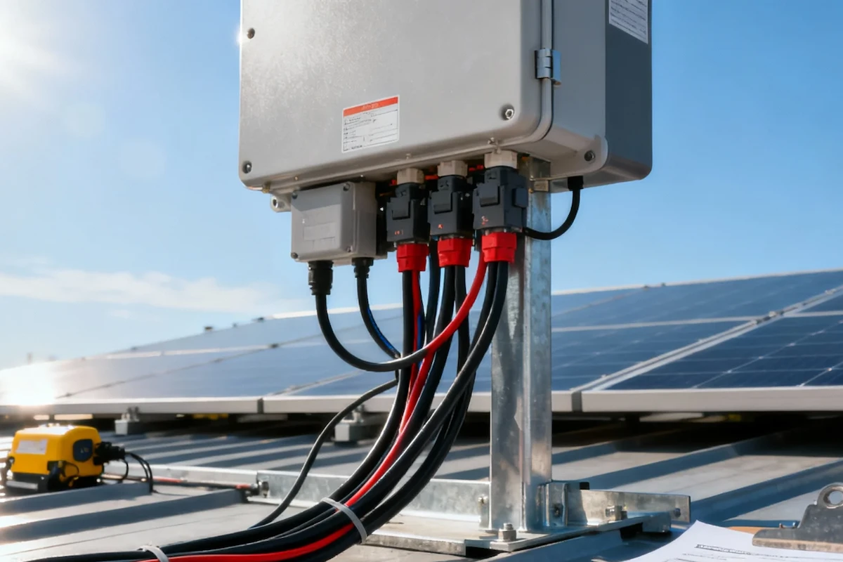
Cable entries represent the most vulnerable points in junction box weather protection. Multiple penetrations multiply potential failure points, making proper entry selection and installation critical for maintaining IP ratings.
Cable glands provide the most reliable sealing for individual cables entering junction boxes. Compression-style glands create watertight seals by compressing an elastomer seal around the cable jacket. The gland threads into pre-tapped holes in the box, creating a second seal between gland and box body. Quality cable glands maintain IP66 or IP67 rating when properly sized and installed.
Select gland size matching cable outer diameter precisely. Oversized glands cannot compress adequately regardless of tightening force. Undersized glands damage cable jackets during installation. Many junction boxes include metric (M16, M20, M25) or PG-threaded entries. Verify gland thread standard matches box threads—mixing metric and PG threads causes improper sealing.
Liquid-tight flexible conduit connections suit applications requiring flexibility or where conduit already exists. Liquid-tight fittings thread into junction box entries similarly to cable glands. The flexible conduit itself provides additional cable protection and strain relief. However, liquid-tight connections cost more than direct cable glands and take more space inside the box due to the conduit ferrule.
Cord grips with mesh accommodate multiple small cables through single entries, reducing required penetration count. These devices grip cable bundles while maintaining weather sealing. However, cord grips provide less secure strain relief than individual cable glands. Use cord grips for low-stress applications like monitoring circuits rather than main power cables subject to thermal expansion forces.
Knockout plugs and blanks seal unused entries essential for maintaining IP rating. Every unfilled entry compromises weather protection regardless of how well occupied entries are sealed. Use threaded metal blanks with O-ring seals rather than snap-in plastic plugs. Metal blanks maintain seal through thermal cycling and resist UV degradation.
⚠️ Important : Never use silicone sealant to fill unused knockouts. Sealant degrades under UV exposure and temperature cycling. Use only proper threaded blanks rated for the box’s IP class. A single improperly sealed unused entry compromises the entire enclosure.
Proper junction box mounting ensures the enclosure maintains position and weather sealing throughout the system’s service life. Mounting method varies based on installation location and substrate material.
Montage en surface attaches junction boxes directly to structural surfaces using screws or bolts through mounting flanges. This method provides simplest installation and best resistance to vibration or thermal movement. For rooftop solar installations, mount boxes to structural members rather than roofing material. Use stainless steel or corrosion-resistant fasteners appropriate for the mounting surface material.
Seal mounting holes to prevent water infiltration behind the box. Apply appropriate sealant under mounting flange before securing fasteners. For metal roof installations, use EPDM or butyl tape sealants designed for metal roofing. Avoid silicone sealants that don’t adhere well to dusty or oily metal surfaces.
Conduit-supported mounting hangs junction boxes from rigid conduit stubs rather than surface mounting. NEC 314.23 allows conduit support for boxes up to 100 cubic inches when using two or more conduit entries positioned to prevent twisting. Conduit threads must be wrench-tight with at least five threads engaged. This mounting suits locations without convenient structural surfaces.
Strut-channel mounting provides flexible positioning for equipment arrays. Mounting brackets attach junction boxes to standard strut channel used for cable management or equipment racks. This method allows easy relocation during installation refinements. However, strut mounting provides less vibration resistance than direct surface mounting. Use this method primarily for protected locations or where repositioning flexibility outweighs stability concerns.
Orientation considerations affect water drainage and cable entry stress. Mount boxes with cable entries facing downward or sideways when possible. Top cable entries allow water to pool around glands despite weather-resistant ratings. Downward entries provide gravity-assisted drainage while reducing stress on cable glands from conductor weight.
🎯 Pro Tip : For rooftop installations, photograph junction box mounting before and after installation. Documentation proves proper attachment to structural members if questions arise during inspections. Photos also help later troubleshooting by showing original configuration.
Junction boxes must achieve appropriate ingress protection ratings for the installation environment. Understanding IP rating requirements and how installation practices affect achieved protection ensures code-compliant installations.
IEC 60529 defines the IP rating system used worldwide for classifying degrees of protection against solid objects and liquids. The first digit (0-6) indicates protection against solid ingress including dust. The second digit (0-9) specifies liquid ingress protection relevant to weather exposure.
Indice de protection IP65 provides adequate protection for most rooftop solar junction boxes. This rating offers dust-tight construction (first digit 6) and protection against water jets from any direction (second digit 5). IP65 withstands typical rain exposure and periodic cleaning with water spray. Standard residential and commercial solar installations typically specify IP65 minimum for outdoor junction boxes.
IP66 rating adds protection against powerful water jets for exposed installations subject to driving rain. This enhanced rating suits coastal locations, high-wind areas, or ground-mounted systems where direct weather exposure exceeds typical rooftop conditions. The increased protection costs minimally compared to IP65 while providing significant reliability improvement in harsh environments.
IP67 rating provides temporary water immersion protection up to 1 meter depth for up to 30 minutes. This rating becomes necessary for ground-mounted junction boxes in areas with flooding risk. While IP67 boxes cost more and offer fewer entry options than IP65/IP66, they prevent catastrophic failure in flood conditions that would destroy lower-rated enclosures.
💡 Aperçu clé : An IP rating only guarantees protection when ALL cable entries use proper glands rated for the same IP class and ALL unused entries are sealed with proper blanks. A single improperly sealed entry immediately compromises the entire box’s weather protection.
Installation practices determine whether boxes maintain their rated protection. Verify all cable glands are torqued properly per manufacturer specifications. Check that gaskets remain properly seated in their channels. Confirm latches engage fully to maintain gasket compression. Annual inspections should verify continued IP rating compliance.
Proper grounding protects against electric shock hazards and ensures effective operation of overcurrent protective devices. Junction boxes require specific grounding provisions especially critical for solar DC circuits.
Equipment grounding conductors must terminate at grounding terminals or bars within junction boxes. NEC 250.8 requires listed pressure connectors, terminal bars, or machine screws for grounding connections. Wire nuts alone don’t provide adequate grounding connections. Junction boxes must include dedicated grounding terminals or accept add-on grounding bars.
Metal junction boxes require bonding to the equipment grounding system. Connect an equipment grounding conductor from the box to the solar array equipment grounding conductor. Size equipment grounding conductors per NEC 250.122 based on the rating of overcurrent protection ahead of the junction box. For solar strings without overcurrent devices, size grounding conductors per NEC 690.45.
Polycarbonate and non-metallic junction boxes don’t require box grounding but must provide grounding terminal provisions for equipment grounding conductor splices. All equipment grounding conductors running through the box must connect together. Non-metallic boxes simplify grounding by eliminating concerns about bonding the enclosure itself.
Grounding electrode connections don’t normally occur at junction boxes unless the box specifically serves as a transition point to a grounding electrode conductor. If junction boxes do house grounding electrode conductor connections, use only listed methods rated for the conductor size and material per NEC 250.70.
⚠️ Important : Never rely on cable gland threads or mounting screws for grounding continuity. These connections degrade over time from corrosion and thermal cycling. Always run dedicated equipment grounding conductors terminated to proper grounding terminals.
Verify grounding connections resist both the maximum fault current and expected lightning surge currents. Solar installations face higher lightning exposure than typical electrical systems. Equipment grounding conductors protect DC SPDs et Disjoncteurs DC from damage during surge events.
Junction boxes serve specific functions at various points in solar PV system conductor runs. Understanding typical applications helps specify appropriately sized and configured boxes.
String-to-harness transitions represent the most common junction box application in solar installations. Individual strings from panel groups terminate in junction boxes where they connect to larger harness conductors leading to Boîtes de raccordement PV. These junction boxes typically house 4-8 string conductors connecting to one harness conductor pair. Size boxes generously to accommodate wire bending radius for the larger harness conductors.
Array segmentation points use junction boxes to create accessible connection points within large solar arrays. Rather than running individual strings hundreds of feet to combiner locations, installers create intermediate junction points. This approach reduces conductor losses and provides convenient service access points. However, each junction adds potential failure points requiring careful weatherproofing.
Conduit transitions between rooftop and interior spaces often require junction boxes as pull points. Long conduit runs benefit from intermediate access points that simplify cable pulling. While these boxes may not house permanent splices, they must still maintain weather protection. Size these pull boxes per NEC 314.28 straight-pull requirements rather than splice-volume calculations.
Monitoring circuit connections use small junction boxes to house connections between production meters, monitoring systems, and communication circuits. These low-voltage circuits still require weather protection equivalent to main power conductors. Dedicated monitoring junction boxes prevent confusion with high-voltage DC connections and simplify troubleshooting.
Transition to AC circuits may occur in junction boxes when systems include AC collection circuits. These boxes must maintain separation between DC and AC circuits per NEC 690.4(B). Use partition barriers or separate boxes for DC and AC circuits. Mark all junction boxes clearly to indicate circuit type and voltage present.
| Application | Taille typique | Caractéristiques principales | IP Rating |
|---|---|---|---|
| String Combiner Junction | 8″×8″×4″ to 12″×12″×6″ | Multiple cable entries, terminal blocks | IP65 min |
| Conduit Pull Point | 6″×6″×4″ to 10″×10″×4″ | Large conduit entries, minimal internals | IP65 min |
| Monitoring Connections | 4″×4″×2″ to 6″×6″×3″ | Small cable entries, minimal volume | IP54 min |
| Array Segmentation | 10″×10″×4″ to 14″×14″×6″ | Many entries, large conductors | IP66 recommended |
Proper wire management inside junction boxes affects both installation aesthetics and long-term reliability. Organized conductors simplify troubleshooting while preventing connection failures from conductor stress.
Acheminement des conducteurs should minimize sharp bends that stress wire insulation. NEC Table 312.6(A) specifies minimum bending radius based on conductor size. For typical solar conductors (10-6 AWG), maintain minimum bending radius of 4-5 times the conductor diameter. Tighter bends risk insulation damage especially when conductors flex during thermal cycling.
Strain relief prevents mechanical stress from reaching spliced connections. Secure cables within 12 inches of entering the junction box using integral strain relief features, cable ties, or adhesive-backed anchors. This prevents conductor weight or cable movement from pulling on splice connections. Strain relief becomes particularly important for heavy harness conductors or installations subject to wind vibration.
Splice organization using terminal blocks provides superior reliability compared to direct wire-to-wire splices with wire nuts. Terminal blocks create mechanically stable connections resistant to vibration and thermal cycling. They also simplify troubleshooting and future modifications. Use terminal blocks rated for outdoor use with adequate creepage distances for solar DC voltages.
Polarity segregation prevents accidental positive-to-negative contact during service. Route positive conductors along one side of the junction box with negative conductors along the opposite side. Use different colored wire markers or labels to maintain clear identification. For systems operating at 600V DC or higher, segregation becomes critical for safety.
Ground bundling keeps all equipment grounding conductors together for easy identification and testing. Connect all grounds to a common grounding terminal or bar. Avoid routing grounding conductors among current-carrying conductors where they might be mistaken for circuit conductors during future service.
🎯 Pro Tip : Take photos of completed wire management before closing junction boxes. These photos become valuable references during future troubleshooting. They also provide quality documentation for inspections and help train less-experienced technicians.
Use wire labels at every conductor entry point and splice point. Solar installations may operate 25+ years with multiple service events. Clear labeling prevents confusion and errors during maintenance performed by technicians unfamiliar with original installation.
Regular junction box inspection prevents moisture-related failures and maintains system reliability. Establishing maintenance schedules appropriate to installation environment ensures long-term performance.
Annual visual inspections should examine external condition without opening boxes. Check mounting security, cable gland tightness, gasket visible condition, and evidence of water infiltration. Look for corrosion around mounting fasteners indicating water intrusion behind the box. Verify cable strain relief remains secure.
Bi-annual internal inspections require opening junction boxes to examine splice connections and internal condition. Schedule these inspections during favorable weather to minimize moisture exposure risk. Check for:
Connection torque verification ensures reliable conductor terminations. Thermal cycling loosens screw terminals over time. Re-torque all splice connections during internal inspections using appropriate torque tools. Follow manufacturer specifications for terminal blocks and connectors. For typical solar applications, this ranges from 7-12 lb-in for 12-10 AWG conductors.
Gasket replacement typically occurs every 3-5 years depending on environmental exposure. Replace gaskets showing cracking, permanent compression set, or loss of elasticity. Clean gasket channels thoroughly before installing new gaskets. Apply thin silicone grease to new gaskets before closure.
Inspection après la tempête should follow major weather events. High winds, hail, or flooding may compromise junction box integrity. Inspect for visible damage, loose mounting, or signs of water infiltration. Address any issues immediately before further weather exposure causes component damage.
⚠️ Important : Always follow LOTO (lockout/tagout) procedures before opening junction boxes on energized solar systems. Even junction boxes without protective devices carry dangerous DC voltage. Verify circuits are de-energized using proper testing equipment before touching conductors.
Document all inspection findings and maintenance performed. Tracking junction box condition over time identifies developing problems and guides preventive maintenance schedules. Documentation also provides valuable warranty support if premature failures occur.
Understanding typical junction box failures helps diagnose problems quickly and implement effective solutions. Most issues relate to moisture ingress or connection degradation.
Moisture inside closed boxes indicates gasket failure, cable gland leaks, or damaged box bodies. Systematically inspect each potential entry point. Loosen and re-tighten all cable glands with proper torque. Replace hardened or damaged gaskets. Examine box body and cover for cracks allowing water entry. Check unused entries have proper threaded blanks rather than simple snap plugs.
Corrosion at connections results from moisture exposure combined with dissimilar metals. Even small amounts of condensation cause corrosion over time. Address moisture source first, then clean corroded connections with wire brush. For severely corroded connections, cut conductors back to clean copper and remake splices. Consider applying dielectric grease to connections in high-humidity environments.
Overheating evidence like discolored insulation or melted conductor insulation indicates connection resistance problems. Loose terminal block screws create high resistance that generates heat. This often occurs gradually as thermal cycling loosens connections. Re-torque all connections and measure conductor temperature during operation. Replace any conductors with damaged insulation.
Tripped breakers or blown fuses downstream from junction boxes may indicate short circuits from damaged splices or moisture-caused faults. Inspect junction box connections carefully for contact between positive and negative conductors. Water bridging between conductors can create intermittent faults. Test insulation resistance between polarities with megohmmeter before re-energizing.
Visible box damage from UV degradation or physical impact requires immediate replacement. Cracked or yellowed plastic boxes have lost mechanical strength and will fail completely under stress. Don’t attempt repairs with tape or sealant—replace compromised boxes entirely. Document failure for warranty claims if premature degradation occurs.
💡 Aperçu clé : Most junction box failures occur at cable entry points rather than from box body failures. Invest in quality cable glands and proper installation rather than focusing solely on premium box bodies. A budget box with excellent cable sealing outperforms a premium box with poor gland installation.
Junction boxes must comply with relevant electrical codes and standards to ensure safety and pass inspections. Understanding applicable requirements prevents costly installation corrections.
Article 314 du NEC provides comprehensive requirements for outlet, device, pull, and junction boxes including installation, sizing, and support. This article applies universally to junction boxes regardless of application. Key provisions include:
NEC 690.31(G) requires secure support for wiring methods in PV installations using fittings listed and identified for use. This applies to cable glands and conduit fittings entering junction boxes. Use only listed fittings designed for outdoor solar applications.
UL 50 establishes standards for enclosures for electrical equipment including junction boxes. UL Type ratings provide weather protection specifications. Type 4 and 4X enclosures provide weather-resistant protection suitable for outdoor solar installations. Type 4X adds corrosion resistance important for coastal locations.
Local amendments to NEC may impose additional requirements. Some jurisdictions require metallic junction boxes, mandate specific mounting methods, or establish minimum IP ratings beyond NEC baseline. Verify local code requirements before specifying junction boxes.
Junction box costs vary based on size, material, features, and IP rating. Understanding cost factors helps balance initial expense against long-term reliability.
Material costs range from $15-20 for basic 4″×4″ plastic junction boxes to $200+ for large weatherproof metal enclosures. Mid-range UV-stabilized polycarbonate boxes (8″×8″×4″) typically cost $40-80. These costs represent small percentages of total solar installation expense but affect long-term reliability significantly.
Installation labor often exceeds material costs, especially for complex wire management. Junction boxes with helpful features (integrated terminal blocks, strain relief pointsRetry, pre-threaded cable entries) reduce installation time substantially. Time saved during installation often justifies higher upfront box costs. Consider total installed cost rather than box price alone.
Maintenance costs accumulate over the system’s 25+ year lifespan. Premium junction boxes with quality gaskets and corrosion-resistant hardware require minimal maintenance—perhaps gasket replacement every 5 years. Budget boxes may need gasket replacement every 2-3 years plus more frequent inspections. Service call costs quickly exceed any initial savings from cheaper boxes.
Failure costs make reliability critical. A failed junction box can damage expensive components like Disjoncteurs DC or cause system downtime. For commercial installations, lost production during repairs costs far more than the junction box itself. Residential systems face similar concerns with added customer satisfaction issues from repeated service calls.
Standardization value reduces inventory and training costs for installation companies. Using consistent junction box specifications across projects simplifies procurement and allows technicians to become expert with specific products. This efficiency gain often outweighs price differences between products.
| Facteur de coût | Budget Box | Mid-Range Box | Premium Box |
|---|---|---|---|
| Initial Purchase | $25 | $60 | $120 |
| Installation Labor | $80 (longer install) | $60 (standard) | $50 (easier install) |
| Maintenance (25 years) | $300 (frequent gaskets) | $150 (standard schedule) | $75 (minimal service) |
| Failure Risk | $400 (likely replacement) | $100 (possible issues) | $25 (very unlikely) |
| Total 25-Year Cost | $805 | $370 | $270 |
🎯 Pro Tip : For commercial installations, perform lifecycle cost analysis including downtime costs. A single day of lost production on a 500kW system can exceed the cost of premium junction boxes for the entire project. Reliability becomes paramount for revenue-generating installations.
Proper junction box labeling ensures safe maintenance and simplifies troubleshooting throughout the system’s lifespan. Comprehensive identification prevents dangerous errors during service.
External labels must include:
Use UV-resistant labels designed for outdoor exposure. Standard laser-printed labels fade within months. Industrial-grade vinyl labels with UV-resistant printing maintain legibility for years. Alternatively, use embossed metal tags that never fade.
Internal labels identify individual conductors and connection points. Mark each conductor at entry point and at termination. Use consistent labeling scheme across all junction boxes in the installation. For example:
Conduit labels at entries identify where conductors originate and terminate. This helps troubleshooting by showing circuit paths without opening multiple boxes. Use wire markers or adhesive labels inside the box near each conduit entry.
Weatherproof label materials must withstand UV exposure, temperature extremes, and moisture. Options include:
Avoid paper labels, standard vinyl, or laser-printed labels without UV protection. These materials fail rapidly outdoors, leaving unlabeled junction boxes that create safety hazards during future maintenance.
⚠️ Important : NEC 690.4(D) requires permanent labels at PV system disconnects and combiner boxes. While junction boxes without protective devices don’t specifically require labeling under this section, proper identification is essential for safety and code compliance under general requirements.
Choosing appropriate junction boxes for solar PV installations requires evaluating multiple factors beyond just meeting minimum code requirements. Consider these selection criteria:
Application requirements determine basic specifications:
Environmental factors affect material and rating selection:
Indicateurs de qualité séparer les produits fiables des alternatives problématiques :
Installation efficiency features reduce labor costs:
Long-term serviceability affects total cost of ownership:
🔵 SYNODE Solution : SYNODE boîtes de distribution étanches incorporate many features beneficial for junction box applications. UV8-stabilized polycarbonate construction withstands decades of outdoor exposure. Pre-threaded metric cable entries accept standard compression glands. Continuous silicone gaskets maintain IP66 protection. DIN rail mounting accommodates terminal blocks for organized splicing. These enclosures serve dual purpose as both equipment boxes and premium junction boxes.
Some solar installations require specialized junction box applications beyond basic string combining or conduit transitions.
Rapid shutdown junction boxes house module-level rapid shutdown devices required by NEC 690.12. These boxes must accommodate additional conductor connections for control circuits activating shutdown devices. Specify larger boxes accounting for both power conductors and control wiring. Maintain separation between high-voltage DC and low-voltage control circuits.
Monitoring junction boxes house revenue-grade meters, production monitors, or communication equipment. These applications may require:
Transition junction boxes between DC and AC circuits require careful planning. NEC 690.4(B) requires DC and AC conductors to be routed separately or installed in different raceways/enclosures. If space constraints require single junction boxes, install permanent barriers separating DC and AC conductors. Label both sides clearly.
Grounding junction boxes at array grounding points house connections between equipment grounding conductors and grounding electrode conductors. These boxes require:
Expansion junction boxes provide provisions for future system additions. Install boxes sized for future connections even if initially unused. Provide additional cable entries for future conductors. Document expansion provisions in system documentation. This foresight simplifies system upgrades without requiring junction box replacement.
Designing junction box installations with future modifications in mind prevents costly rework during system expansions or modifications.
Oversizing boxes by 20-30% beyond minimum NEC requirements accommodates future additions. The incremental cost is minimal during initial installation but massive during retrofits requiring box replacement. Larger boxes also simplify installation by providing working space.
Extra cable entries allow future connections without drilling boxes and compromising IP ratings. Install threaded blanks in unused entries. Document blank locations for future reference. This approach works well for staged installations where final configuration isn’t yet determined.
Accessible mounting locations allow future maintenance without heroic efforts. Consider access requirements for technicians with tools and testing equipment. Rooftop junction boxes should be reachable without standing on modules. Ground-mount boxes should have adequate clearance for kneeling work.
Documentation provisions like label attachment points or QR code tags help maintain system information over decades. Solar installations often change ownership multiple times. Good documentation prevents knowledge loss that complicates future work.
Standard components simplify future maintenance by ensuring replacement parts remain available. Using proprietary junction boxes from small manufacturers risks unavailability years later. Specify products using industry-standard gaskets, cable glands, and mounting methods.
What’s the difference between a junction box and a combiner box in solar installations?
Junction boxes provide protected spaces for wire splices and connections without housing protective devices. They’re essentially weatherproof splice enclosures following general NEC wiring rules. Combiner boxes house Disjoncteurs DC, Fusibles DCet DC SPDs that provide overcurrent protection and surge protection for solar strings. Combiner boxes require specific ratings for DC interruption and must meet additional requirements under NEC Article 690. Both need weather protection, but combiner boxes also need proper ratings for the protective devices inside.
How do I calculate the minimum junction box size for my application?
Use NEC Article 314.16 for boxes containing splices. Count each conductor entering the box once. Count each wire nut or connector as one conductor. Count internal clamps as one conductor. Count all grounding conductors as one conductor. Multiply total count by the volume allowance from NEC Table 314.16(B) for your largest conductor size. For example, 8 conductors of 10 AWG (2.5 cubic inches each) plus 4 wire nuts plus 1 clamp plus grounds = (8+4+1+1) × 2.5 = 35 cubic inches minimum. Add 20-30% margin for working space and future additions.
Can I use indoor junction boxes outdoors if they’re under a roof overhang?
No, never use indoor-rated boxes for any outdoor location even under shelter. Indoor boxes lack proper gasket sealing, UV-resistant materials, and weatherproof cable entry provisions. Temperature cycling creates condensation even in covered locations, damaging connections over time. Covered installations may use IP54-rated boxes instead of IP65, but still require outdoor-rated construction. The cost difference between indoor and outdoor boxes is minimal compared to the risk of moisture damage to solar circuits carrying dangerous DC voltages.
How often should I inspect outdoor junction boxes?
Perform annual external inspections checking mounting security, visible gasket condition, and cable gland tightness without opening boxes. Conduct internal inspections every 2-3 years examining splice connections, looking for corrosion or moisture evidence, and verifying connection torque. In harsh coastal or industrial environments, inspect more frequently—potentially every 6 months externally and annually internally. Also inspect after major weather events like hurricanes or hailstorms. Document all inspections to track condition over time and identify developing problems.
What IP rating do I need for rooftop solar junction boxes?
Rooftop solar junction boxes typically require IP65 minimum rating providing dust-tight protection and water jet resistance from any direction. This handles normal rain exposure and periodic cleaning. For roofs with severe weather exposure (coastal locations with driving rain, high-wind areas, or minimal drainage), specify IP66 for enhanced water jet protection. IP67 (temporary water immersion protection) becomes necessary only for ground-mounted boxes in flood-prone areas. Most rooftop residential and commercial installations perform well with IP65-rated junction boxes from quality manufacturers.
Can I repair cracked junction boxes with sealant instead of replacing them?
Never attempt repairs on cracked or damaged junction boxes—always replace them completely. Cracks indicate UV degradation or impact damage that compromises structural integrity throughout the box. Sealants provide only temporary fixes that fail under thermal cycling, UV exposure, and weather. A cracked box cannot maintain its IP rating regardless of sealant application. The modest cost of replacement boxes is insignificant compared to the risk of moisture damage to spliced connections or potential safety hazards from exposed high-voltage DC circuits. Replace damaged boxes immediately and document failures for warranty claims if premature.
Do junction boxes need to be listed or certified for solar use?
Junction boxes for solar installations must be listed to appropriate standards (UL, CSA, or equivalent) as general-purpose enclosures suitable for the application. Unlike Boîtes de raccordement PV housing protective devices that require specific solar ratings, junction boxes follow general electrical enclosure standards. They must meet NEC requirements for construction, mounting, and environmental protection. The listing must cover outdoor use (Type 4/4X or equivalent IP rating) and maximum voltage present. Some jurisdictions require additional certifications. Verify local requirements beyond base NEC code.
Outdoor electrical junction boxes provide essential protected connection points in solar PV systems where multiple circuits join, transition, or branch. Proper selection based on conductor count, environmental conditions, and installation location ensures reliable performance throughout 25+ year system lifespans.
Quality junction boxes with UV-stabilized polycarbonate construction, proper IP ratings, and robust cable gland sealing deliver superior reliability compared to budget alternatives. The small incremental cost for premium materials and features is justified by reduced maintenance requirements and eliminated failure risks over decades of operation.
Professional installation practices—proper sizing calculations, secure mounting, correct cable gland installation, organized wire management, and comprehensive labeling—determine whether junction boxes maintain their protection ratings and support safe system operation. Regular inspection and preventive maintenance further ensure continued reliability.
Principaux enseignements :
SYNODE manufactures professional-grade weatherproof enclosures suitable for junction box applications in demanding solar PV installations. Our UV8-stabilized polycarbonate construction withstands decades of outdoor exposure while maintaining structural integrity and weather sealing.
SYNODE Enclosure Advantages for Junction Box Applications:
Our enclosures integrate seamlessly with complete SYNODE solar protection systems including Disjoncteurs DC, Fusibles DC, DC SPDs, Interrupteurs-sectionneurs à courant continuet Boîtes de raccordement PV. CE, TÜV, and UL certifications ensure global compliance.
Ready to specify junction boxes for your solar project? Contact SYNODE’s technical team for application-specific recommendations, sizing calculations, and competitive quotations. We support solar professionals in 50+ countries with reliable products, technical guidance, and responsive customer service.