Adresse
304 North Cardinal
St. Dorchester Center, MA 02124
Heures de travail
Du lundi au vendredi : de 7h00 à 19h00
Le week-end : 10H00 - 17H00
Adresse
304 North Cardinal
St. Dorchester Center, MA 02124
Heures de travail
Du lundi au vendredi : de 7h00 à 19h00
Le week-end : 10H00 - 17H00


Solar fuses in professional PV system design form coordinated protection tiers that isolate faults at the lowest level, maintaining maximum system availability during equipment failures. A single fuse blowing should disconnect only the faulty string, not the entire array—achieving this requires precise selectivity analysis, time-current curve coordination, and strategic placement throughout the DC distribution architecture.
This system design guide examines solar fuses from the protection engineer’s perspective. We analyze multi-tier protection strategies (string level, combiner level, array main level), selectivity requirements between upstream and downstream fuses, I²t energy let-through calculations, fault current analysis, and the complete design methodology for commercial and utility-scale PV installations.
For electrical engineers, system designers, and protection specialists designing solar arrays from 50kW to multi-MW scale, proper fuse coordination prevents both nuisance outages (oversized fuses that don’t isolate faults quickly) and cascade failures (undersized fuses that blow unnecessarily under normal conditions).
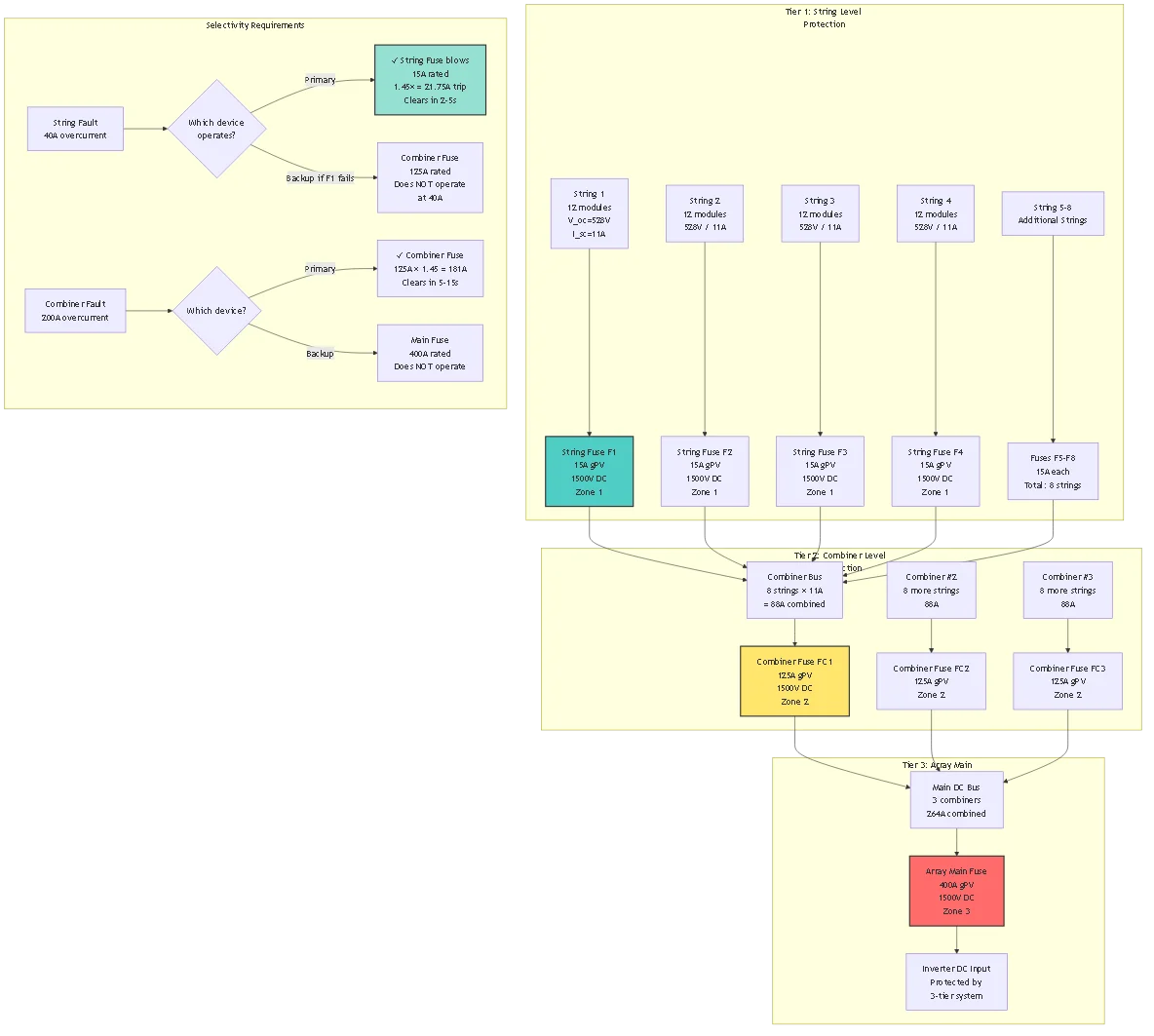
💡 Design Philosophy: Each protection tier should operate only for faults within its zone. String fuses clear string faults, combiner fuses clear combiner bus faults, main fuses clear array-to-inverter faults. Proper selectivity means upstream devices remain closed during downstream fault clearing.
Tier 1 – String Level Protection:
Fonction: Isolate individual faulty strings without affecting parallel strings
Device: Individual fuses per string (typically 10-25A, 1000-1500V DC)
Fault types protected:
– String internal short circuit (module failure)
– Reverse current from parallel strings into shaded/failed string
– String-to-ground faults
– Cable insulation failures
Design Parameters:
– Current rating: I_fuse ≥ I_sc × 1.56 per NEC 690.9
– Voltage rating: ≥ V_oc_max at coldest temperature
– Breaking capacity: 50 kA minimum (gPV standard)
– Time-current: Fast-acting (I²t < 1000 A²s at 10× In) Tier 2 – Combiner Level Protection:
Fonction: Protect combiner bus and feeder cables to next-level equipment
Device: Combiner output fuse or circuit breaker (typically 100-400A)
Fault types protected:
– Combiner bus shorts (bus bar fault, terminal failure)
– Feeder cable faults between combiner and recombiner/inverter
– Reverse current from other combiners in large arrays
Design Parameters:
– Current rating: I ≥ (N_strings × I_sc × 1.25) / 0.80
– Selectivity with string fuses: Must not operate during string fault
– Breaking capacity: Based on array short-circuit current calculation
– Time-current: Delayed relative to string fuses (I²t > 2× string fuse)
Tier 3 – Array Main Protection:
Fonction: Final protection before inverter DC input, array isolation
Device: Main DC breaker or fuse (typically 400-3200A for large systems)
Fault types protected:
– Inverter input short circuit
– DC bus faults in recombiner
– Ground faults in main DC distribution
– Backfeed from inverter during grid disturbances
Design Parameters:
– Current rating: Total array I_sc × 1.25 / 0.80
– Selective with combiners: Delayed time-current characteristic
– Breaking capacity: Maximum available fault current at inverter location
– Integration: Often includes disconnect switch function
Overlapping Zones for Reliability:
Zone 1: Individual String
  └─ Protected by: String Fuse (F1)
  └─ Backup: Combiner Fuse (F2)
Zone 2: Combiner Output └─ Protected by: Combiner Fuse (F2) └─ Backup: Array Main (F3)
Zone 3: Array to Inverter └─ Protected by: Array Main (F3) └─ Backup: Inverter internal protection
Design Goal: Primary device clears fault within its zone; backup device only operates if primary fails.
Selectivity Ratio: For proper coordination:
– F2 (combiner) current rating ≥ 1.6× F1 (string) rating
– F3 (main) current rating ≥ 1.6× F2 (combiner) rating
– Time-current separation: 200-300ms minimum at fault current level
Fuse Time-Current Characteristic:
Solar fuses follow inverse-time characteristic: higher overcurrent causes faster melting.
Key Points on Curve:
1. Conventional Non-Fusing Current (I_nf):
– Current that fuse carries for 2 hours WITHOUT blowing
– Typically I_nf = 1.25 × I_n
– Example: 15A fuse, I_nf = 18.75A
2. Conventional Fusing Current (I_f):
– Current that CAUSES fusing within 2 hours
– Typically I_f = 1.45 × I_n
– Example: 15A fuse, I_f = 21.75A
3. Fast-Acting Region (3-20× I_n):
– Typical clearing time: 0.1-10 seconds
– Example: 15A fuse at 150A (10×) clears in ~0.5 seconds
4. Short Circuit Region (>20× I_n):
– Clearing time: <0.1 seconds – Limited by I²t rating – Example: 15A fuse at 1500A (100×) clears in ~0.01 seconds
Ratio Method for Fuse Selection:
For guaranteed selectivity, current ratings should follow:
I_upstream / I_downstream ≥ 1.6 (minimum ratio)
Application to 3-Tier System:
| Tier | Calibre du fusible | Selectivity Ratio | Vérification |
|---|---|---|---|
| String Fuse | 15A | Baseline (1.0) | - |
| Combiner Fuse | 125A | 125 / 15 = 8.3× | ✓ 8.3 > 1.6 minimum |
| Array Main Fuse | 400A | 400 / 125 = 3.2× | ✓ 3.2 > 1.6 minimum |
Méthode de vérification: Plot time-current curves on log-log paper:
– At any given current level, upstream fuse clearing time must be >300ms longer than downstream fuse
– This ensures downstream fuse clears before upstream sees enough I²t to melt
I²t Definition:
I²t represents energy let-through: ∫ I²(t) dt measured in A²s (ampere-squared seconds)
Physical Meaning:
– Energy absorbed by downstream equipment before fault clears
– Heating effect on conductors: Temperature rise ∝ I²t
– Semiconductor damage threshold: Each device has maximum I²t rating
Coordination Requirement:
I²t_upstream >> I²t_downstream (at same fault current)
This ensures downstream fuse always melts first, protecting upstream fuse from unnecessary operation.
Exemple de calcul:
String fault: 150A (10× string fuse rating)
String Fuse (15A):
– Clearing time: 0.5 seconds (from manufacturer curve)
– I²t = I² × t = 150² × 0.5 = 11,250 A²s
Combiner Fuse (125A):
– At 150A current (only 1.2× its rating), this is below I_nf
– Combiner fuse experiences heating but does NOT melt
– I²t contribution to combiner: 150² × 0.5 = 11,250 A²s
– Combiner fuse I²t withstand rating at 1.2×: ~500,000 A²s
- Ratio: 500,000 / 11,250 = 44× margin ✓
Combiner fault: 500A (4× combiner fuse rating)
Combiner Fuse (125A):
– Clearing time: 2.0 seconds (from curve)
– I²t = 500² × 2.0 = 500,000 A²s
Main Fuse (400A):
– At 500A current (1.25× its rating), below I_nf
– Main fuse does NOT melt
– I²t withstand at 1.25×: ~5,000,000 A²s
- Ratio: 5,000,000 / 500,000 = 10× margin ✓
🎯 Design Rule: Maintain minimum 3:1 I²t ratio between upstream and downstream fuses for reliable selectivity under all fault conditions.
System Parameters:
– Total capacity: 500kW
– Voltage: 1000V DC nominal, 1100V V_oc_max
– Module: 400W, V_oc = 44V, I_sc = 11.2A
– Configuration: 100 strings × 25 modules
– Organized: 10 combiners × 10 strings each
Tier 1 – String Protection:
I_string = 11.2A × 1.56 = 17.5A minimum
Selected: 20A gPV fuse, 1500V DC, 14×51mm
– Conventional fusing current: 20A × 1.45 = 29A (blows in 2 hours)
– Fast-acting: 20A × 10 = 200A (blows in 0.5s)
– I²t at 10×: 15,000 A²s
Tier 2 – Combiner Protection:
I_combiner = (10 strings × 11.2A × 1.25) / 0.80 = 175A
Selected: 200A gPV fuse, 1500V DC, 22×58mm
– Conventional fusing current: 200A × 1.45 = 290A
– Fast-acting: 200A × 5 = 1000A (blows in 1.0s)
– I²t at 5×: 800,000 A²s
Selectivity ratio: 200A / 20A = 10× ✓ (well above 1.6 minimum)
Tier 3 – Array Main Protection:
I_main = (100 strings × 11.2A × 1.25) / 0.80 = 1750A
Selected: 2000A circuit breaker, 1500V DC (fuse impractical at this current)
– Trip setting: 2000A × 1.25 = 2500A (1.25× overload)
– Short-time delay: 0.3 seconds (allows combiner fuses to clear first)
– Instantaneous trip: 10,000A (5× rating)
Selectivity ratio: 2000A / 200A = 10× ✓
Selectivity Verification:
Fault at String #1:
– String fault current: 9 strings × 11.2A = 100.8A reverse
– String fuse F1-1: Sees 100.8A → Clears in 1.2 seconds
– Combiner fuse FC1: Sees 100.8A (0.5× rating) → NO OPERATION ✓
– Main breaker: Sees 100.8A (0.05× rating) → NO OPERATION ✓
Fault at Combiner #1 Output:
– Combiner fault current: 10 strings × 11.2A = 112A
– Combiner fuse FC1: Sees 112A (0.56× rating)
– Wait… 112A < 200A, fuse won’t blow! – Problem identified: Combiner output bolted fault produces only string current
Revised Analysis – Combiner Bus Fault:
For bolted fault on combiner bus, fault current limited by:
– String fuses: 10 × 20A = 200A maximum
– Combiner fuse must coordinate with STRING fuses, not string current
Corrected selectivity check:
– If one string shorts internally: String fuse clears 100A in 1.2s, combiner sees this for 1.2s but doesn’t melt (I²t margin 80×)
– If combiner bus shorts: All 10 string fuses blow simultaneously, combiner fuse sees 200A total, may or may not blow depending on clearing time race
Design Improvement: Use circuit breaker at combiner output instead of fuse:
– Breaker can be adjusted for 250A trip setting with 0.5s delay
– Provides coordination with string fuses
– Resettable for troubleshooting

PV Array Fault Current is Current-Limited:
Unlike grid sources with nearly infinite fault current, PV arrays are limited by module physics:
I_fault_max = N_parallel × I_sc × 1.25
Où ?
– N_parallel = number of parallel strings feeding fault point
– I_sc = module short-circuit current
– 1.25 = high irradiance factor
Example – 100 String Array:
Fault at main DC bus (all strings contribute):
– I_fault = 100 strings × 11.2A × 1.25 = 1400A
Compare to grid fault:
– Utility transformer: 1000 kVA, 1000V, %Z = 5%
– I_fault_grid = 1000 kVA / (1000V × 0.05) = 20,000A
Implication: PV fault currents are manageable—even large utility-scale arrays rarely exceed 10,000A. Standard gPV fuses with 50 kA breaking capacity provide 5-50× margin.
Location 1 – String Internal Fault:
Fault current = (N – 1) × I_sc × 1.25 (reverse current from other strings)
For 10-string combiner:
– I_fault = 9 × 11.2A × 1.25 = 126A
String fuse rating: 20A
Overcurrent ratio: 126A / 20A = 6.3×
Clearing time from curve: 0.8 seconds
Location 2 – Combiner Bus Fault:
Fault current limited by string fuses:
– I_fault ≤ N_strings × I_fuse_rating
– Example: 10 × 20A = 200A maximum
If combiner fuse rated 200A, this is exactly 1.0× rating—fuse will take hours to blow. Combiner must be rated lower (125-160A) OR use circuit breaker with adjustable trip.
Location 3 – Main DC Bus Fault:
Fault current from all combiners:
– I_fault = N_combiners × (N_strings × I_sc × 1.25)
– Example: 10 combiners × 10 strings × 11.2A × 1.25 = 1400A
Main breaker rating: 2000A
Ratio: 1400A / 2000A = 0.7×
Problème: Under-loaded—fault current doesn’t reliably trip breaker. Must reduce main breaker rating to 1600A or install sensitive ground fault detection.
NEC 690.5 Ground Fault Protection:
Required for all systems >50 kW with array voltage >50V to ground.
Detection Method:
Monitor insulation resistance between DC system and ground:
– Normal: >1 MΩ
– Warning: <500 kΩ – Fault: <10 kΩ
Ground Fault Current:
I_ground = V_system / (R_fault + R_system)
Exemple :
– System voltage: 1000V DC
– Ground fault resistance: 10Ω (bolted fault)
– System resistance: 2Ω (wire, connections)
– I_ground = 1000V / 12Ω = 83A
Défi: 83A ground fault may not trip 2000A main breaker. Requires dedicated ground fault protection relay.
Solution: Install residual current device (RCD) or ground fault protection relay:
– Detects imbalance between positive and negative current
– Typical setting: 300mA sensitivity for personnel protection, 5A for equipment protection
– Opens main breaker via auxiliary trip when ground current exceeds setting

When to Mix Fuses and Breakers:
| Localisation | Type d'appareil | Raison d'être |
|---|---|---|
| String level | Fuses | Low cost, compact, precise I²t, single-use acceptable |
| Combiner output | Circuit breaker | Resettable, adjustable trip, frequent access |
| Array main | Circuit breaker | High current capacity, disconnect function, metering |
Coordination Fuse-to-Breaker:
Breakers have adjustable thermal (I_t) and magnetic (I_mag) trip settings:
Exemple:
– String fuses: 20A
– Combiner breaker: 125A, adjustable thermal 0.8-1.0× In, magnetic 5-10× In
Settings for selectivity:
– Thermal: 1.0× (125A trip in 60 minutes at 1.25×)
– Magnetic: 8× (1000A instantaneous trip)
– Short-time delay: 0.5 seconds
Vérification :
– String fault 126A: String fuse clears in 0.8s, breaker sees this but thermal not reached (0.8s << 60min) ✓ – Combiner fault 500A: Breaker magnetic at 1000A, so doesn’t trip instantly; thermal at 500A clears in 8-10 seconds ✓ – Main fault 1500A: Breaker magnetic trips instantly (<0.1s) ✓
Ambient Temperature Impact:
Fuses and breakers both derate with temperature, but at different rates:
| Température ambiante | Fuse Derating | Breaker Derating | Coordination Impact |
|---|---|---|---|
| 25°C (STC) | 1.00 (nominal) | 1.00 (nominal) | Designed coordination valid |
| 50°C | 0.90 | 0.93 | Coordination maintained |
| 70°C | 0.80 | 0.85 | Coordination slightly degraded |
High Temperature Risk:
At 70°C combiner box temperature:
– String fuse effective rating: 20A × 0.80 = 16A
– Combiner breaker effective rating: 125A × 0.85 = 106.25A
– Selectivity ratio: 106.25 / 16 = 6.6× (was 6.25× at 25°C)
Coordination improves slightly at high temperature (both devices trip faster but ratio maintained).
Cold Temperature Issue:
At -20°C:
– Module V_oc increases 13-15%
– Module I_sc increases 2-3%
– Fuse sees higher inrush during morning startup
Design practice: Size fuses based on I_sc at 25°C × 1.25 (high irradiance). This inherently provides margin for cold temperature I_sc increase.
N+1 Combiner Architecture:
For utility-scale systems requiring maximum availability:
Standard Design:
– 10 combiners × 100A = 1000A total
– Main breaker: 1250A
– Single combiner failure: 10% capacity loss
N+1 Design:
– 11 combiners × 100A = 1100A total (10% excess)
– Main breaker: 1250A
– Single combiner failure: System continues at full rated capacity
Protection Coordination:
– Each combiner: 100A fuse or breaker
– Main: 1250A breaker with monitoring
– Ground fault: 5A sensitive relay on each combiner
Impact sur les coûts:
– Additional combiner: $3,000-5,000
– Additional cabling: $1,500-2,500
– Total: +$5,000 for 500kW system (+$10/kW)
– Benefit: Zero downtime during combiner maintenance/failure

1. System Architecture Definition:
– [ ] Total array capacity (kW)
– [ ] Number of strings and modules per string
– [ ] Number of combiner boxes and strings per combiner
– [ ] Inverter(s) DC input specifications
– [ ] Voltage range: V_mpp, V_oc_min, V_oc_max
– [ ] Module specifications: I_sc, I_mpp, temperature coefficients
2. Environmental Parameters:
– [ ] Maximum ambient temperature in combiner boxes
– [ ] Minimum ambient temperature (for V_oc calculation)
– [ ] Altitude (if >2000m, apply derating)
– [ ] Pollution degree (coastal, industrial, clean)
3. Code Compliance Requirements:
– [ ] NEC 690.9 overcurrent protection
– [ ] NEC 690.5 ground fault protection (if >50kW)
– [ ] State/local amendments to NEC
– [ ] Utility interconnection requirements
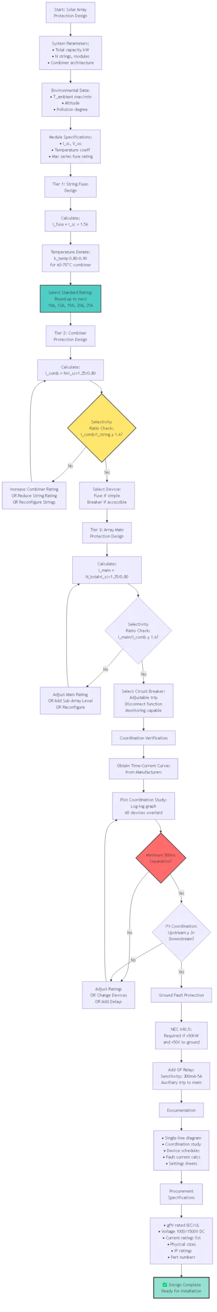
4. Tier 1 – String Fuse Selection:
– [ ] Calculate: I_fuse ≥ I_sc × 1.56
– [ ] Apply temperature derating
– [ ] Select standard gPV rating
– [ ] Verify voltage rating ≥ V_oc_max
– [ ] Check module datasheet max series fuse rating
– [ ] Specify physical size (10×38, 14×51, 22×58)
– [ ] Select fuse holder (IP rating, wire termination capacity)
5. Tier 2 – Combiner Protection Selection:
– [ ] Calculate: I_comb = (N_strings × I_sc × 1.25) / 0.80
– [ ] Verify selectivity ratio vs string fuses (≥1.6×)
– [ ] Check I²t coordination
– [ ] Decide: Fuse or circuit breaker?
– [ ] If breaker: Set thermal and magnetic trip points
– [ ] Verify breaking capacity ≥ maximum fault current
6. Tier 3 – Array Main Protection:
– [ ] Calculate: I_main = (N_total_strings × I_sc × 1.25) / 0.80
– [ ] Verify selectivity ratio vs combiner devices (≥1.6×)
– [ ] Select circuit breaker (typically, due to high current)
– [ ] Configure adjustable trip settings
– [ ] Integrate disconnect and monitoring functions
– [ ] Add ground fault protection relay (NEC 690.5)
7. Coordination Verification:
– [ ] Obtain time-current curves from all manufacturers
– [ ] Plot on log-log coordination study
– [ ] Verify 300ms minimum separation at all fault current levels
– [ ] Check I²t coordination: upstream ≥ 3× downstream
– [ ] Verify selectivity at maximum and minimum fault currents
8. Documentation:
– [ ] Single-line diagram showing all protection devices
– [ ] Coordination study with time-current curves
– [ ] Device schedules (rating, type, manufacturer, part number)
– [ ] Fault current calculations for each location
– [ ] Settings sheets for adjustable breakers
9. Procurement Specifications:
– [ ] Fuse type: gPV per IEC 60269-6 ou UL 2579
– [ ] Voltage rating: 1000V or 1500V DC
– [ ] Current ratings: [list each tier]
– [ ] Physical sizes: [specify 10×38, 14×51, etc.]
– [ ] Fuse holder IP rating: IP65 minimum outdoor
– [ ] Circuit breaker: DC-rated, electronic trip, communication capable
10. Commissioning Verification:
– [ ] Visual inspection: Correct fuses installed in each position
– [ ] Polarity check: Positive and negative correctly identified
– [ ] Torque verification: Terminals tightened to specification
– [ ] Insulation resistance test: >1 MΩ system-to-ground
– [ ] Function test: Trip one string fuse, verify others continue
– [ ] Ground fault test: Inject test signal, verify relay operation
Selectivity requires minimum 1.6:1 current rating ratio between upstream (combiner) and downstream (string) fuses. Example: 15A string fuses require ≥24A combiner fuses; in practice, use next standard rating (25A minimum). Additionally, verify I²t coordination: at any fault current level, upstream fuse’s I²t withstand must be >3× downstream fuse’s let-through I²t. Plot manufacturer time-current curves on log-log coordination study to verify >300ms separation at all fault currents. If selectivity fails, increase combiner fuse rating, reduce string fuse rating, or change combiner to adjustable circuit breaker with time delay.
This creates coordination problems—the fuse won’t reliably clear faults within its protection zone. Example: combiner bus fault produces 180A, but combiner fuse rated 200A. At 0.9× rating, fuse takes 4+ hours to blow (far too slow). Solutions: (1) Reduce fuse rating to ensure fault current exceeds 1.25× rating minimum; (2) Replace fuse with circuit breaker having adjustable trip set at 1.25× expected fault current; (3) Install sensitive fault detection relay that trips breaker at lower currents. For ground faults producing <25% of rated current, dedicated ground fault relays (300mA-5A sensitivity) are mandatory per NEC 690.5.
No—each string’s fuse must match its specific I_sc. Mixed-module arrays require separate calculations: String A with I_sc=11A needs 11×1.56=17.16A → 20A fuse; String B with I_sc=9A needs 9×1.56=14.04A → 15A fuse. Using oversized fuses (20A for all strings) leaves lower-current strings underprotected against reverse current. Using undersized fuses causes nuisance trips on high-current strings during cloud-edge enhancement. Document each string type clearly on single-line diagrams and label fuse positions accordingly. For maintenance simplicity, some designers standardize on highest-I_sc fuse rating across all strings, accepting slight cost increase for lower-I_sc string overprotection.
High combiner box temperatures (60-70°C rooftop installations) reduce both fuse and breaker capacity by 15-20%. Critical design impact: calculate all ratings at expected maximum temperature, not 25°C standard. Example: 20A fuse at 70°C effectively becomes 16A. Fortunately, both upstream and downstream devices derate proportionally, maintaining selectivity ratios. However, fault clearing times increase at high temperatures (element takes longer to reach melting point), slightly degrading protection speed. Design conservatively: size string fuses for coldest temperature I_sc increase (×1.13 at -20°C) but verify capacity at hottest ambient using temperature derating factors from manufacturer datasheets.
Inverter manufacturers specify maximum let-through I²t their semiconductor switches can withstand without damage—typically 10,000-50,000 A²s for utility-scale inverters. Select fuses with let-through I²t (at prospective fault current) <50% of inverter I²t rating for safety margin. Example: Inverter max I²t = 40,000 A²s at 1000A fault current. Fuse let-through at 1000A (from manufacturer curve): 8,000 A²s. Ratio: 40,000/8,000 = 5× margin ✓. If insufficient margin, use faster-acting fuse, reduce fuse rating (increases I²t withstand relative to fault current), or add current-limiting reactors upstream of inverter.
NEC 690.9(A) requires overcurrent devices in all ungrounded DC conductors. For typical ungrounded (floating) PV systems: fuse BOTH positive and negative. For grounded systems where negative is bonded to earth: fuse only positive (NEC 690.9(B) exception). However, modern practice increasingly fuses both conductors even in grounded systems for several reasons: (1) symmetry simplifies maintenance and troubleshooting; (2) provides protection regardless of where ground fault occurs; (3) facilitates future conversion to ungrounded configuration; (4) cost difference minimal (2× fuses instead of 1×). Large utility systems may omit negative fuses for cost savings in grounded designs, but residential/commercial systems typically fuse both.
Inverters contain internal DC input protection (typically electronic monitoring with IGBT shutdown, sometimes backup fuses). Proper coordination ensures external array fuses clear first for array faults, inverter protection activates only for internal inverter faults. Design approach: (1) Obtain inverter maximum DC input current specification (e.g., 250A continuous); (2) Size array main fuse/breaker for 250A × 1.25 = 313A → use 315A or 400A rating; (3) Verify inverter internal protection set points (typically 1.5-2× continuous rating = 375-500A); (4) At array fault producing 300A, external 315A fuse clears in 30-120 seconds, inverter sees this but doesn’t trip (below 375A threshold) ✓. Inverter protection provides backup if external fuse fails and handles internal DC link capacitor inrush or failure modes.
Solar fuses system design transcends simple device selection—proper protection requires multi-tier architecture with precisely coordinated selectivity ensuring faults clear at the lowest level without cascading to upstream devices. Effective designs isolate individual string failures while maintaining array availability, protect expensive inverter electronics through I²t limiting, and comply with NEC ground fault detection requirements for systems >50kW.
Critical Design Principles:
Three-Tier Architecture: String-level fuses (15-25A) protect individual PV strings and provide reverse current isolation. Combiner-level fuses or breakers (100-250A) protect combiner bus and feeders. Array main breakers (400-3200A) provide final protection before inverter with disconnect and monitoring functions. Each tier sized using NEC 690.9 methodology with 1.56× multiplier for strings, (N×I_sc×1.25)/0.80 for combiners.
Selectivity Requirements: Minimum 1.6:1 current rating ratio between adjacent tiers ensures downstream devices clear first. Verify coordination with time-current curves: >300ms separation at all fault current levels. I²t coordination critical: upstream device I²t withstand ≥3× downstream device let-through at common fault currents.
Fault Current Analysis: PV arrays are current-limited—maximum fault current = N_parallel × I_sc × 1.25. Unlike grid faults (20-100 kA), PV faults typically <10 kA even in utility-scale systems. This simplifies protection: standard 50 kA gPV fuses provide substantial margin. However, limited fault currents create challenges coordinating oversized protection devices—must size carefully to ensure fault current exceeds 1.25× device rating. Temperature and Environmental Corrections: Size all devices considering maximum combiner box temperature (60-70°C typical rooftop). Apply 15-20% capacity derating for high temperatures. Simultaneously verify cold-temperature V_oc doesn’t exceed voltage ratings. Ground fault protection mandatory >50kW per NEC 690.5—sensitive relays (300mA-5A) required as standard overcurrent devices may not detect low-magnitude ground faults.
For protection engineers and system designers, coordinated solar fuses enable safe, reliable PV systems that maintain availability during faults and protect personnel and equipment throughout 25-30 year project lifecycles.
Related Protection Engineering Resources:
- Principes de base des fusibles pour panneaux solaires – Fundamental fuse technology
- Conception d'une boîte de raccordement PV – Complete combiner specifications
- DC Circuit Breaker Coordination – Breaker-based protection
Engineering Services: SYNODE provides protection coordination studies for solar projects >500kW including time-current curve analysis, fault current calculations, and device selection optimization. Contact our power systems engineering team for coordination study services and NEC compliance verification.
Dernière mise à jour : Octobre 2025
Auteur : SYNODE Protection Engineering Team
Examen technique : Professional Engineers (PE), NABCEP PV Designers
Standards Referenced: Article 690 du NEC:2023, IEC 60269-6:2016, IEEE 1547:2018