Adresse
304 North Cardinal
St. Dorchester Center, MA 02124
Heures de travail
Du lundi au vendredi : de 7h00 à 19h00
Le week-end : 10H00 - 17H00
Adresse
304 North Cardinal
St. Dorchester Center, MA 02124
Heures de travail
Du lundi au vendredi : de 7h00 à 19h00
Le week-end : 10H00 - 17H00


La série de normes IEC 62305 représente le cadre international le plus complet pour la conception de systèmes de protection contre la foudre (LPS), remplaçant de nombreuses normes nationales et fournissant une méthodologie unifiée pour la protection des structures et des systèmes contre les effets de la foudre. Pour les installations solaires, cette norme offre des conseils essentiels qui ne figurent pas dans les codes de l'électricité, tels que Article 690 du NEC-L'interception des coups directs, la gestion des champs électromagnétiques, la coordination de la protection contre les surtensions et la conception de la mise à la terre pour les défis uniques que posent les systèmes photovoltaïques.
Publiée en quatre parties entre 2006-2010 et mise à jour jusqu'en 2024, la norme CEI 62305 aborde la protection contre la foudre de manière holistique : évaluation du risque déterminant la nécessité de la protection (partie 2), conception du système de protection physique (partie 3), protection des systèmes électriques et électroniques (partie 4), et protection des services entrant dans les structures (partie 1, principes généraux). Pourtant, des études sur le terrain révèlent que seulement 30-35% des installations solaires commerciales sont entièrement conformes aux recommandations de l'IEC 62305 - de nombreux concepteurs se contentent des exigences minimales du NEC sans savoir que le code électrique traite des risques de choc et d'incendie, mais pas de la prévention complète des dommages causés par la foudre.
Ce guide technique explique l'application de la norme IEC 62305 spécifiquement pour la protection des systèmes solaires. Vous apprendrez la structure de la norme en quatre parties, les calculs d'évaluation des risques déterminant les exigences en matière de niveau de protection, le concept de zone de protection pour une protection coordonnée contre les surtensions, les classes I à IV du système de protection contre la foudre (LPS) avec les paramètres de conception correspondants, et la sélection des composants garantissant une protection coordonnée contre les frappes directes à travers l'électronique connectée. Qu'il s'agisse de concevoir des réseaux au sol ou des installations commerciales sur les toits, la norme CEI 62305 fournit les bases techniques d'une protection fiable contre la foudre.
💡 Regard critique: La norme CEI 62305 fait passer la protection contre la foudre d'une approche réactive (réparation des dommages après les coups) à une approche proactive (prévention des dommages grâce à une conception basée sur le risque) - calcul de la probabilité de perte acceptable et conception de systèmes de protection permettant d'atteindre l'objectif de réduction du risque.
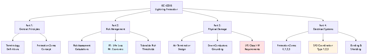
La série CEI 62305 divise la protection contre la foudre en quatre parties interconnectées, chacune traitant d'aspects spécifiques de la protection globale.
Objectif: Établit les concepts fondamentaux, la terminologie et les exigences de protection applicables à toutes les applications de protection contre la foudre.
Définitions clés:
Système de protection contre la foudre (LPS): Système complet de terminaison d'air, de conducteurs de descente, d'électrodes de mise à la terre, de composants de liaison et de dispositifs de protection contre les surtensions assurant une protection contre les coups directs et les effets indirects.
Zone de protection: Espace tridimensionnel où le champ électromagnétique de la foudre est atténué à des niveaux sans danger pour l'équipement protégé. Les zones imbriquées offrent une protection de plus en plus efficace.
Distance de séparation: Distance minimale entre les composants de protection contre la foudre et les systèmes protégés afin d'éviter la formation d'étincelles dangereuses (side-flash) lors des coups de foudre.
Niveau de protection contre la foudre (LPL): Classification I-IV définissant les paramètres de courant de foudre minimum et maximum que le système de protection doit gérer. Détermine le rayon de la sphère de roulement, la taille des mailles et les valeurs nominales des composants.
Objectif: Fournit une méthodologie pour calculer le risque de foudre sur les structures et déterminer la justification économique des systèmes de protection.
Processus d'évaluation des risques:
Étape 1 : Identifier les types de risques
- R1 : Risque de perte de vies humaines
- R2 : Risque de perte de service au public
- R3 : Risque de perte du patrimoine culturel
- R4 : Risque de perte de valeur économique
Étape 2 : Calculer les composantes du risque
Risque lié aux grèves directes sur la structure, aux grèves à proximité de la structure, aux grèves sur les services connectés et aux grèves à proximité des services. Chaque composante comprend la probabilité d'occurrence d'une grève et la probabilité de pertes consécutives.
Étape 3 : Déterminer le risque tolérable
L'annexe A de la norme CEI 62305-2 définit les niveaux de risque tolérables :
- R1 (perte de vie) : 10-⁵ par an (1 chance sur 100 000 par an)
- R2 (perte de service) : 10-³ par an
- R4 (perte économique) : Déterminé par une analyse économique
Étape 4 : Comparer le risque calculé au risque tolérable
Si le risque calculé dépasse le seuil tolérable, des mesures de protection sont nécessaires. La norme fournit des facteurs d'efficacité des mesures de protection, ce qui permet une conception itérative optimisant le coût par rapport à la réduction du risque.
Considérations spécifiques à l'énergie solaire: L'empreinte d'un grand réseau augmente la probabilité d'un impact (composante de la zone de collecte). Les systèmes électroniques et de surveillance des onduleurs, qui ont une grande valeur, augmentent l'ampleur des pertes. Les sites éloignés peuvent avoir une réponse d'urgence limitée, ce qui augmente le risque d'incendie pour la sécurité des personnes.
Objectif: Spécifie la terminaison d'air, le conducteur de descente et la conception de l'électrode de mise à la terre afin d'éviter tout dommage physique dû à une fixation directe de la foudre.
Exigences de base:
Placement des terminaisons d'air: Utilise la méthode de la sphère roulante dont le rayon dépend de la classe LPS (20 m pour la classe I, 60 m pour la classe IV). Tout point de la structure touché par la sphère roulante doit être protégé.
Nombre et espacement des conducteurs de descente: Au moins deux conducteurs de descente pour les structures avec périmètre <50m, four conductors for perimeter >50m. Espacement maximal entre les conducteurs : 10 m pour la classe I, 25 m pour la classe IV.
Résistance de l'électrode de terre: Cible <10Ω pour une performance fiable. La norme fournit des méthodes de calcul pour différents types d'électrodes (tiges, anneaux, électrodes de fondation).Exigences en matière de cautionnement: Tous les systèmes métalliques et les composants structurels de la structure doivent être reliés au LPS afin d'éviter les différences de tension dangereuses pendant les grèves.
Objectif: La protection contre les surtensions concerne les équipements électroniques sensibles - onduleurs, systèmes de surveillance, équipements SCADA - vulnérables aux champs électromagnétiques et aux surtensions conduites.
Concept de zones de protection: Divise la structure en zones de protection imbriquées avec une intensité de champ électromagnétique décroissante :
Zone 0: Protection extérieure LPS, champ électromagnétique de foudre complet
Zone 1: Structure intérieure avec LPS externe, champ réduit
Zone 2: A l'intérieur d'une pièce ou d'une armoire blindée, champ encore réduit
Zone 3: Blindage au niveau de l'équipement, champ minimal
Coordination des DOCUP: Les dispositifs de protection contre les surtensions situés aux limites des zones assurent une protection échelonnée. SPD de type 1 au niveau du branchement (zone 0→1), type 2 au niveau du tableau de distribution (zone 1→2), type 3 au niveau de l'équipement sensible (zone 2→3).
Application solaire: Des SPD DC sont nécessaires à l'entrée de l'onduleur, des SPD AC à la sortie de l'onduleur. Des disjoncteurs supplémentaires protègent les circuits de surveillance et les systèmes de communication contre les surtensions induites.
La norme CEI 62305-3 définit quatre niveaux de protection contre la foudre correspondant à des efficacités de protection et à des paramètres de conception différents. Le choix dépend des résultats de l'évaluation des risques et de considérations économiques.
Classe I (protection maximale - efficacité 98%)
Application: Installations critiques, hôpitaux, structures contenant des matériaux explosifs, patrimoine culturel irremplaçable, lieux à forte densité de foudre (>10 éclairs/km²/an).
Paramètres de conception:
- Rayon de la sphère roulante : 20 mètres
- Taille des mailles (conducteurs horizontaux) : 5m × 5m maximum
- Angle de protection : 25° à h=20m
- Courant de foudre minimal : 200 kA (capture des coups du 99e percentile)
- Courant de pointe de la première course : 200 kA
- Énergie spécifique : 10 MJ/Ω
Applications solaires typiques: Installations à grande échelle dans les régions à fort éclairement, systèmes solaires plus stockage avec batteries au lithium, panneaux sur les hôpitaux ou les centres de données.
Classe II (protection renforcée - efficacité du 95%)
Application: Bâtiments commerciaux, installations industrielles à risque moyen, structures où le public se rassemble, la plupart des installations solaires commerciales.
Paramètres de conception:
- Rayon de la sphère roulante : 30 mètres
- Taille des mailles : 10 m × 10 m au maximum
- Angle de protection : 35° à h=20m
- Courant de foudre minimal : 150 kA
- Courant de pointe de la première course : 150 kA
- Énergie spécifique : 5,6 MJ/Ω
Applications solaires typiques: Systèmes commerciaux sur toiture de 50 à 500 kW, systèmes solaires communautaires au sol, réseaux d'installations industrielles.
Classe III (protection standard - efficacité 90%)
Application: Structures commerciales et industrielles standard, bâtiments résidentiels dans des zones de foudre modérée à élevée, installations solaires typiques.
Paramètres de conception:
- Rayon de la sphère roulante : 45 mètres
- Taille des mailles : 15 m × 15 m au maximum
- Angle de protection : 45° à h=20m
- Courant de foudre minimal : 100 kA
- Courant de pointe de la première course : 100 kA
- Énergie spécifique : 2,5 MJ/Ω
Applications solaires typiques: Toitures commerciales de 10 à 100 kW, systèmes résidentiels dans les zones à fort éclairement, la plupart des installations d'abris de voiture et d'auvents.
Classe IV (protection de base - efficacité 80%)
Application: Structures à faible risque, bâtiments agricoles, petites installations résidentielles dans les régions à faible éclairement (<3 flasheskm²year).Paramètres de conception:
- Rayon de la sphère roulante : 60 mètres
- Taille des mailles : 20 m × 20 m au maximum
- Angle de protection : 55° à h=20m
- Courant de foudre minimal : 100 kA
- Courant de pointe de la première course : 100 kA
- Énergie spécifique : 2,5 MJ/Ω
Applications solaires typiques: Systèmes résidentiels <10kw in low-lightning areas, small commercial arrays where economic analysis doesn't justify higher protection.
Facteur 1 : probabilité de grève
Calculer la fréquence annuelle attendue des grèves :
Nd = Ng × Ae × Cd × 10-⁶
Où ?
- Ng = Densité de l'éclair au sol (éclairs/km²/an d'après les cartes isocérauniques)
- Ae = Surface de collecte équivalente de la structure
- Cd = Coefficient environnemental (1,0 isolé, 0,5 urbain)
Exemple: Réseau de 100 m × 50 m dans la région Ng=6 :
Ae = (100+6×20) × (50+6×20) = 220 × 170 = 37 400 m² = 0,0374 km².
Nd = 6 × 0,0374 × 0,5 = 0,112 coups/an (coup tous les 9 ans)
Facteur 2 : conséquences de l'échec
- Risque pour la sécurité des personnes : Requiert la classe I ou II
- Matériel de grande valeur (>$500k) : Classe II au minimum
- Standard commercial : Classe III acceptable
- Résidentiel de faible valeur : La classe IV peut suffire
Facteur 3 : analyse économique
Coût annuel de la protection (capital amorti + entretien) par rapport à la perte annuelle attendue :
- Si le coût de la protection < 0.1 × expected annual loss: Economically justified
- If protection cost > la perte annuelle attendue : Envisager une classe de protection inférieure
| Paramètres | Classe I | Classe II | Classe III | Classe IV |
|---|---|---|---|---|
| Efficacité de la protection | 98% | 95% | 90% | 80% |
| Sphère roulante (m) | 20 | 30 | 45 | 60 |
| Maillage (m) | 5×5 | 10×10 | 15×15 | 20×20 |
| Courant de pointe (kA) | 200 | 150 | 100 | 100 |
| Application solaire typique | Échelle des services publics | Commercial | Petit commerce | Résidentiel |
🎯 Conseil de pro: Lors du choix entre des classes adjacentes (par exemple, classe II ou III), calculez le coût supplémentaire de la protection - souvent seulement 10-20% de matériau en plus, mais offrant 5% de meilleure efficacité de protection, ce qui permet d'éviter un coup dommageable pendant toute la durée de vie du système.

La norme CEI 62305-4 introduit le concept de zone de protection, qui divise les structures en volumes imbriqués dont les niveaux de champ électromagnétique sont progressivement réduits. Cela permet de coordonner la protection contre les surtensions en adaptant la sensibilité à l'intensité du champ.
Zone de protection contre la foudre (LPZ) 0A: Volume exposé aux coups de foudre directs et au champ électromagnétique de la foudre (LEMP). Le système de terminaison aérienne définit la limite entre la zone LPZ 0A et les zones intérieures. Niveau de menace : Courant et champ de foudre complets.
Zone de protection contre la foudre (LPZ) 0B: Volume protégé contre les frappes directes mais exposé à une LEMP totale ou partielle. Exemple typique : intérieur d'une structure avec terminaison d'air externe mais sans blindage électromagnétique. Niveau de menace : Pas de coups directs, champ électromagnétique partiel, surtensions conduites totales sur les services d'entrée.
Zone de protection contre la foudre (LPZ) 1: Volume où les courants de surtension sont limités par des disjoncteurs à la limite de la zone et où le champ électromagnétique est atténué par le blindage de la structure. L'enveloppe métallique du bâtiment ou les conducteurs en grille assurent le blindage. Niveau de menace : Ampleur réduite de la surtension, champ électromagnétique atténué.
Zone de protection contre la foudre (LPZ) 2+: Volumes avec une réduction supplémentaire du champ électromagnétique et une limitation des surtensions. Réalisé par des salles blindées intérieures, des armoires métalliques ou des étages SPD supplémentaires. Niveau de menace : Réduction supplémentaire des surtensions et des champs, adaptée à l'électronique sensible.
Des liens aux frontières: Tous les systèmes conducteurs traversant les limites de la zone doivent être reliés à la barre d'équipotentialité située à la limite. Cela inclut :
- Conducteurs d'alimentation (avec SPD)
- Lignes de communication (avec SPD de signalisation)
- Tuyaux et conduits métalliques
- Acier de construction
- Chemins de câbles et goulottes
Installation du DOCUP: Les dispositifs de protection contre les surtensions s'installent aux limites des zones, protégeant contre les surtensions conduites sur les circuits entrant dans des zones de protection plus élevées.
Continuité du blindage: Le blindage électromagnétique doit être continu et ne pas présenter de lacunes supérieures à λ/10, λ étant la longueur d'onde de la plus haute fréquence concernée (typiquement 1 MHz pour la foudre, λ = 300 m, λ/10 = 30 m).
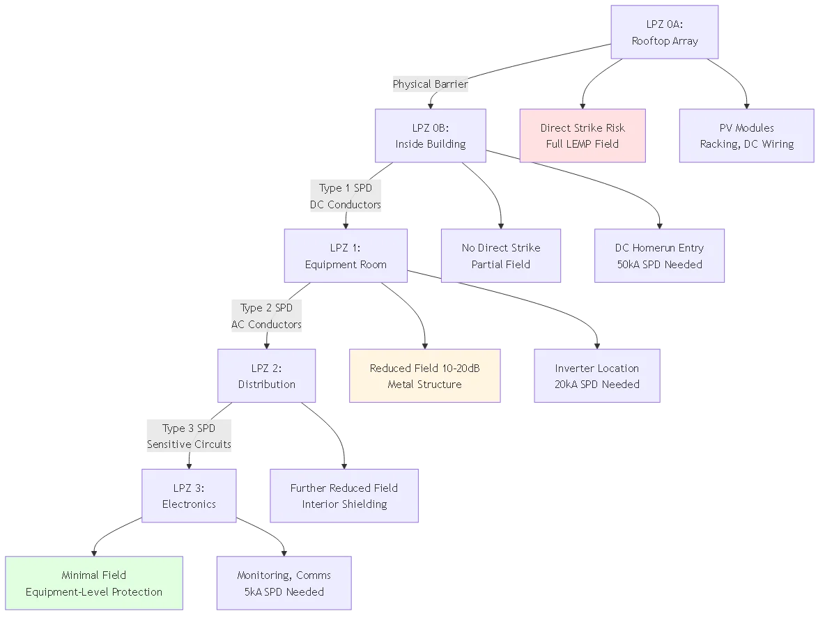
Configuration typique d'un réseau commercial en toiture:
LPZ 0A: Espace sur le toit comprenant les panneaux photovoltaïques, les rayonnages et le câblage externe. Exposition totale aux coups directs et au champ électromagnétique.
Limite du LPZ 0B: Toit/parois d'un bâtiment offrant un abri physique mais un blindage électromagnétique minimal.
LPZ 0B→1 transition: Entrée du conduit de courant continu dans le bâtiment. Installer un SPD DC de type 1 à cette limite pour protéger les conducteurs DC contre les surtensions.
LPZ 1: Salle d'équipement intérieure abritant l'onduleur, la distribution CA, l'équipement de surveillance. La structure métallique du bâtiment fournit un blindage électromagnétique réduisant le champ de 10 à 20 dB.
Transition LPZ 1→2: Sortie CA de l'onduleur entrant dans le panneau électrique principal. Installer un SPD CA de type 2 à cette limite.
LPZ 2: Zone de distribution électrique principale. Réduction supplémentaire sur le terrain à partir des murs intérieurs, des conduits.
LPZ 2→3 transition: Circuits alimentant des équipements sensibles de surveillance, de communication ou de contrôle. Installer des disjoncteurs de type 3 aux entrées de l'équipement.
Stratégie de protection: Chaque transition de zone incorpore un SPD approprié au niveau de menace, limitant progressivement les amplitudes de surtension à des niveaux tolérables par l'équipement dans la zone protégée.
Le choix du dispositif de protection contre les surtensions doit tenir compte de l'emplacement de la zone de protection, de la tension de tenue de l'équipement connecté et de la coordination avec les dispositifs de protection contre les surtensions en amont et en aval.
SPD de type 1 (essai de classe I selon IEC 61643-11)
Application: Limite LPZ 0→1, entrée de service, endroits exposés à un courant de foudre partiel (coup direct sur une ligne de service proche, induction par des coups proches).
Exigences du test: Forme d'onde de 10/350 μs, courant d'impulsion de 25-100 kA. Cette forme d'onde de longue durée simule le courant de foudre réel.
Paramètres de protection:
- Courant de décharge nominal (In) : 25-50 kA (8/20 μs)
- Courant d'impulsion (Iimp) : 25-100 kA (10/350 μs)
- Niveau de protection de la tension (Up) : Typiquement 2,5-4,0 kV pour les systèmes 1000V DC
- Suivre l'interruption du courant : Doit éteindre le courant de défaut CA après la conduction du SPD
Application solaire: SPD DC à l'entrée de la boîte combinée des branches, SPD DC à l'entrée DC de l'onduleur, SPD AC à la sortie AC de l'onduleur (équivalent à l'entrée de service).
SPD de type 2 (essai de classe II)
Application: LPZ 1→2 limite, panneau de distribution, emplacements de sous-panneaux où le SPD de type 1 fournit une protection en amont contre les effets directs.
Exigences du testForme d'onde de 8/20 μs, courant de décharge de 20-40 kA. Durée plus courte que la foudre mais suffisante pour les surtensions induites et les transitoires de commutation.
Paramètres de protection:
- Courant de décharge nominal (In) : 20-40 kA
- Courant de décharge maximal (Imax) : 40-80 kA
- Niveau de protection de la tension (Up) : 2,0-3,0 kV pour les systèmes 1000V
- Temps de réponse : <25 nsApplication solaire: SPD CA au panneau de distribution principal (si Type 1 à l'entrée de service), SPD CC à l'onduleur si Type 1 au combinateur, protection du circuit de surveillance.
Type 3 SPD (Class III test)
Application: LPZ 2→3 boundary, equipment-level protection for sensitive electronics requiring lower voltage protection than Type 1/2 provide.
Exigences du test: Combination wave (1.2/50 μs voltage, 8/20 μs current), lower energy than Type 1/2.
Paramètres de protection:
– Nominal discharge current (In): 5-10 kA
– Voltage protection level (Up): 1.0-1.5 kV for 1000V systems
- Temps de réponse : <25 ns
- fine protection for equipment with low surge immunityApplication solaire: Monitoring equipment inputs, communication circuits (Ethernet, RS-485), control circuits to motor drives or trackers.
Upstream coordination: Ensure Type 1 SPD withstands energy that would otherwise reach Type 2/3 devices. Type 1 must clamp surge below Type 2 maximum rating.
Selectivity: If fault occurs, only the SPD nearest the source should operate, leaving upstream protection intact. Achieved through different clamping voltages and response times.
Backup protection: If Type 1 fails (from exceeded rating or end-of-life), fuse or disconnect must clear fault before damaging protected equipment or causing fire.
Installation separation: IEC 62305-4 recommends minimum 10-meter conductor length between SPD types (or 5m with decoupling inductance) preventing interaction during surge events.
System parameters:
– Array: 100kW rooftop, 300 modules, 10 strings
– Voc: 950V DC maximum
– Location: Ng = 5 flashes/km²/year
– Protection class: LPS Class II
SPD selection:
String combiner (LPZ 0A→0B):
– Type 1 DC SPD required (partial lightning current exposure)
– Iimp: 25 kA minimum (Class II requirement)
– UCPV: 1000V minimum (Voc × 1.2 factor)
– Up: <3.5 kV (inverter withstand typically 6 kV)
- Quantity: 1 per string = 10 SPDsInverter DC input (LPZ 0B→1):
– Type 1 or Type 2 DC SPD depending on distance from combiner
– If <10m from combiner: type 2 acceptable (in = "40" ka)
- if>10m: Type 1 required (Iimp = 25 kA)
– Up: <2.5 kV (lower than combiner SPD for coordination)Inverter AC output (LPZ 1→2):
– Type 2 AC SPD (service entrance equivalent)
– In: 40 kA per phase
– Voltage: 480V three-phase system
– Up: <2.0 kV L-N, <3.5 kV L-PE
IEC 62305-2 provides detailed risk assessment formulas. Practical application for solar installation:
For 50m × 30m commercial building with 75kW rooftop array:
RA: Risk from direct strike to structure (array on roof)
RB: Risk from strike near structure (induced surges)
RC: Risk from strike to utility line (conducted surges)
RD: Risk from strike near utility line (induced on service)
Total risk R = RA + RB + RC + RD
Direct strike to structure (NA):
Collection area Ae = (L+6H) × (W+6H)
– Building: 50m × 30m × 10m height
– Ae = (50+60) × (30+60) = 110 × 90 = 9,900 m² = 0.0099 km²
– NA = Ng × Ae × Cd = 5 × 0.0099 × 0.5 = 0.025 strikes/year
Strike near structure (NB):
NB = Ng × (250m radius circle area – Ae)
NB = 5 × (0.196 – 0.0099) = 0.93 strikes/year (affects electronics via induced surges)
Strike to connected service (NC):
Assumes 100m utility line, overhead construction
Ac = 1000 × 100 = 100,000 m² = 0.1 km²
NC = Ng × Ac × Ce = 5 × 0.1 × 1.0 = 0.50 strikes/year
For each risk component, multiply strike probability by loss probability factors from IEC 62305-2 tables.
Example for RA (direct strike):
RA = NA × PA × LA
Où ?
– PA = probability of damage (depends on LPS class, construction, surge protection)
– LA = consequent loss (life loss, equipment damage, service loss)
Without LPS: PA = 1.0 (unprotected), LA = 0.01 (office building, limited occupancy)
RA = 0.025 × 1.0 × 0.01 = 0.00025
With Class III LPS: PA = 0.1 (90% protection efficiency), same LA
RA = 0.025 × 0.1 × 0.01 = 0.000025
Tolerable risk for life loss: RT = 10⁻⁵ = 0.00001
Without protection: R ≈ 0.00025 (combined all components)
R > RT → Protection required
With Class III LPS + Type 1/2 SPDs: R ≈ 0.000008
R < RT → Adequate protectionConclusion: Class III protection system economically justified, reduces risk below tolerable threshold.

Problème: Installing Type 2 SPD at service entrance (LPZ 0→1 boundary) instead of required Type 1. Type 2 devices lack 10/350 μs withstand capability, failing during direct strike current exposure.
Scénarios courants:
– Using residential-grade AC SPDs (Type 3) at commercial service entrance
– DC SPD at combiner box rated only for 8/20 μs, not 10/350 μs
– Mixing SPD types without verifying energy coordination
Correction: Verify SPD test class matches IEC 61643-11 requirements for installation location. Type 1 mandatory at LPZ 0→1, Type 2 at LPZ 1→2, Type 3 at LPZ 2→3. Check manufacturer datasheets for test waveform (10/350 or 8/20 μs).
Problème: Applying rolling sphere method without accounting for protection class selection. Using 60m radius (Class IV) when Class II required based on risk assessment.
Scénarios courants:
– Defaulting to NEC requirements (essentially Class IV) for commercial installations requiring Class II
– Not performing risk assessment to determine appropriate protection level
– Using protection angle method beyond its valid range (h/H > 0.6)
Correction: Conduct IEC 62305-2 risk assessment determining required protection class. Apply corresponding rolling sphere radius: 20m (Class I), 30m (Class II), 45m (Class III), 60m (Class IV). Document risk calculation justifying class selection.
Problème: Failing to bond all metallic systems at protection zone boundaries. Unbonded systems develop dangerous voltage differences during strikes, causing arcing and equipment damage.
Scénarios courants:
– DC conduit entering building not bonded to grounding system
– Module racking not bonded to building structure
– Communication cables lacking signal line SPDs at zone boundary
– Separate electrical and lightning protection grounds without bonding
Correction: Install equipotential bonding bar at each zone boundary. Bond all conductive systems crossing boundary: power conductors (with SPDs), signal lines (with signal SPDs), metallic pipes/conduits, structural elements. Use minimum 6 AWG bonding conductors, compression terminals, and anti-oxidant compound.
Problème: Single ground rod attempting to serve entire lightning protection system. IEC 62305-3 requires multiple distributed electrodes for effective energy dissipation.
Scénarios courants:
– Relying on electrical service ground rod (one 8-foot rod)
– Not installing grounding ring for large structures
– Ground rods spaced too closely (overlapping resistance spheres)
Correction: Minimum two ground rods for structures with perimeter <50m, four rods for >50m. Space rods ≥2× rod length apart (16 feet minimum for 8-foot rods). Implement grounding ring for arrays exceeding 50kW. Target <10Ω combined resistance verified by fall-of-potential testing.
Problème: Installing protection components without documented design basis or class designation. Prevents verification of code compliance and limits liability protection.
Scénarios courants:
– Designer specifies “lightning protection per NEC” (NEC doesn’t define protection classes)
– Contractor uses available components without engineering analysis
– No as-built drawings showing air termination coverage or SPD locations
Correction: Prepare IEC 62305-compliant design documentation including: risk assessment calculation determining required protection class, rolling sphere analysis showing air termination coverage, SPD coordination plan with type and location specified, grounding system layout with resistance calculations. Provide to building authority for permit approval and maintain for insurance certification.
IEC 62305 compliance can be verified through third-party certification providing insurance discounts and demonstrating due diligence.
TÜV (Technischer Überwachungsverein): German inspection association offering lightning protection system certification per IEC 62305. Reviews design documentation and inspects installed systems. Certification valid 3-5 years with annual re-inspection.
UL (Underwriters Laboratories): North American certification organization. While UL 96A addresses lightning protection, it predates IEC 62305. New installations increasingly reference IEC rather than UL standards.
National Lightning Safety Institute (NLSI): US-based organization providing lightning protection design review and installation inspection. Issues certificates of compliance for IEC 62305-compliant systems.
Design review: Examiner verifies risk assessment calculation, protection class selection justification, rolling sphere coverage analysis, SPD coordination plan, grounding design calculations.
Installation inspection: Inspector verifies conductor sizes meet minimums, air termination covers all exposure points per rolling sphere, grounding resistance <10Ω, bonding continuity <0.2Ω, SPD test class matches installation location.Documentation: Certification file includes design calculations, as-built drawings, test results, maintenance schedule. Required for insurance underwriting and building authority approval in some jurisdictions.
Premium reduction: Many commercial property insurers offer 5-15% premium reduction for certified lightning protection systems. Savings often recover certification cost in 2-3 years.
Claim support: Certified systems demonstrate due diligence. If lightning damage occurs despite protection, certification supports claim that system was properly designed/installed, shifting liability to equipment manufacturer rather than installer/owner.
Required coverage: Some insurers require IEC 62305 certification for solar installations exceeding $500k value or in high-lightning regions (Ng >8). Without certification, coverage may be denied or limited.
IEC 62305 is the international standard series for lightning protection system design published by the International Electrotechnical Commission. It consists of four parts covering general principles, risk assessment, physical protection, and electrical system protection. For solar systems, IEC 62305 provides comprehensive methodology absent from electrical codes like NEC Article 690—addressing direct strike interception through air termination design, surge protection coordination for DC and AC circuits, grounding system requirements for energy dissipation, and electromagnetic field management protecting sensitive electronics. The standard introduces the protection zone concept dividing installations into nested volumes with progressively reduced lightning threat, enabling coordinated SPD selection. It defines four Lightning Protection System classes (I-IV) corresponding to 98%-80% protection efficacy, allowing designers to match protection level to risk assessment results. While not legally mandatory in most jurisdictions, IEC 62305 compliance demonstrates engineering best practice, supports insurance underwriting, and increasingly required for building permits on commercial solar installations exceeding 50kW.
LPS Class I (98% protection, 20m rolling sphere) applies to critical facilities and high-lightning regions. Class II (95% protection, 30m sphere) suits commercial buildings and most commercial solar 50-500kW. Class III (90% protection, 45m sphere) covers standard commercial and residential systems in moderate lightning areas. Class IV (80% protection, 60m sphere) applies to low-risk structures in minimal lightning regions. Selection depends on IEC 62305-2 risk assessment calculating strike probability and consequence. Residential systems <10kw typically use class iii or iv unless high lightning density (>5 flashes/km²/year) or life safety concerns dictate Class II. Commercial installations 10-100kW generally require Class II or III depending on occupancy, equipment value, and lightning exposure. Utility-scale systems >500kW typically specify Class II minimum due to large footprint increasing strike probability and high equipment concentration. Each class defines corresponding design parameters: Class II uses 30m rolling sphere for air termination coverage, 10m×10m mesh maximum, 150kA minimum protection current. Higher classes cost 10-20% more than adjacent lower class but provide 5% better protection efficacy.
IEC 62305-2 provides risk assessment methodology calculating strike probability and comparing to tolerable risk thresholds. Process involves: (1) Calculate expected annual strike frequency using local ground flash density (Ng), structure collection area, and environmental factors. Example: 100m×50m array in Ng=5 region expects 0.11 strikes/year. (2) Determine risk type—R1 for life loss, R4 for economic loss. Each has tolerable threshold: R1 = 10⁻⁵ (1 in 100,000 annually), R4 determined by cost-benefit analysis. (3) Calculate total risk from four components: direct strikes to structure, strikes near structure, strikes to entering services, strikes near services. Each component multiplies strike probability by damage probability and consequent loss. (4) Compare calculated risk to tolerable threshold. If R > RT, protection required; if R < RT, protection optional but may be economically justified. For most commercial solar installations, risk assessment shows protection economically beneficial—cost of LPS system ($5,000-25,000) significantly less than expected annual loss from unprotected strikes. Residential systems may fall below mandatory threshold but protection still advisable in lightning-prone regions.
The protection zone concept divides structures into nested volumes (LPZ 0, 1, 2, 3) with decreasing electromagnetic field intensity from lightning. LPZ 0A (outside, full exposure) transitions to LPZ 0B (inside structure, partial field) then LPZ 1 (reduced field via building shielding) and higher zones with further field reduction. At each zone boundary, install appropriate surge protective devices and bonding components. Implementation for typical commercial solar: LPZ 0A contains rooftop array exposed to direct strikes. Building roof creates LPZ 0B boundary—install Type 1 DC SPD where DC conductors enter building (40-50kA discharge current, 10/350μs test waveform). Interior equipment room becomes LPZ 1 with metal structure providing 10-20dB field attenuation—install Type 2 AC SPD at inverter output (20-40kA, 8/20μs test). Sensitive monitoring equipment occupies LPZ 2 with additional shielding—install Type 3 SPDs on communication circuits (5-10kA). Bond all metallic systems (conduits, pipes, structural steel) crossing each boundary to equipotential busbar at that boundary. This staged approach progressively limits surge magnitudes from 100kA+ at LPZ 0 to <5ka at sensitive equipment, matching protection to threat level.
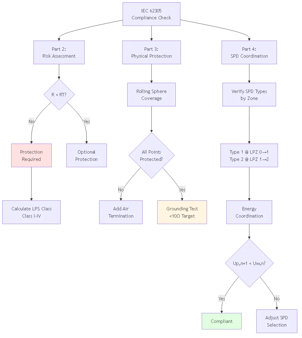
SPD type selection depends on location within protection zone structure and test class per IEC 61643-11. Type 1 (Class I test) required at LPZ 0→1 boundary where partial lightning current exposure possible—service entrance, DC homerun entry from rooftop array, connections to overhead utility lines. Must withstand 10/350μs test waveform (25-100kA impulse current) simulating actual lightning. Type 2 (Class II test) installs at LPZ 1→2 boundary for distribution panels, inverter locations with upstream Type 1 protection, sub-panels. Tested to 8/20μs waveform (20-40kA) adequate for induced surges after Type 1 has limited direct effects. Type 3 (Class III test) provides equipment-level protection at LPZ 2→3 for sensitive electronics requiring lower clamping voltage—monitoring systems, communication equipment, control circuits. Energy coordination requires voltage protection level of downstream SPD (Up,n+1) less than withstand voltage of protected equipment (Uw,n). Install 10-meter minimum conductor length between SPD types or use decoupling inductance preventing interaction. Common mistake: installing residential Type 3 devices at commercial service entrance requiring Type 1. Verify manufacturer datasheet specifies correct test waveform for intended location.
Compliance testing involves three phases: design verification, installation inspection, and performance testing. Design verification reviews risk assessment calculations ensuring protection class selection justified, rolling sphere analysis confirming all exposure points covered, SPD coordination verifying energy ratings match zone requirements. Inspection during installation checks conductor sizes (2 AWG copper minimum for lightning protection, 6 AWG for bonding), air termination placement, bonding connections have star washers penetrating coatings, torque specifications met (7-9 N⋅m module frames, 15-20 N⋅m ground clamps). Performance testing after completion measures grounding resistance using fall-of-potential method (target <10Ω), verifies bonding continuity between components (<0.2Ω resistance), confirms SPD installation per manufacturer requirements. Testing frequency: initial commissioning, annually during maintenance, after known lightning strikes, after any system modifications affecting protection. Engage third-party certification body (TÜV, NLSI) for formal compliance certificate supporting insurance underwriting—costs $2,000-8,000 depending on system size but provides premium discounts recovering cost in 2-3 years. Document all testing with photos, resistance measurements, and SPD specifications for building authority approval and future reference.
IEC 62305 compliance typically adds 15-30% to lightning protection costs compared to minimum NEC requirements, but this incremental investment provides substantially better protection and insurance benefits. Example commercial 100kW rooftop system: Basic NEC compliance (essentially Class IV protection) costs $8,000-12,000 including grounding electrodes, equipment bonding, and Type 2 SPDs. IEC 62305 Class II system costs $12,000-18,000—requires additional air termination devices for 30m rolling sphere coverage vs 60m NEC equivalent, Type 1 SPDs at LPZ boundaries vs Type 2 only, larger grounding conductors (2 AWG vs 6 AWG), and more electrodes achieving <10Ω vs <25Ω. However, benefits include: 95% vs 80% protection efficacy potentially avoiding one damaging strike over 25-year system life ($50,000+ loss), 5-15% insurance premium reduction ($500-2,000 annual savings), improved permit approval and inspection pass rates, third-party certification supporting liability defense. For utility-scale installations >500kW, IEC compliance becomes economically compelling—incremental cost $0.02-0.04/watt adds $10,000-40,000 to $1-2M total system cost (0.5-2% premium) while reducing lightning damage risk by 15-18 percentage points. Residential systems see higher percentage cost impact (30-40%) but absolute dollars remain modest ($1,500-3,000 incremental for Class III compliance).
IEC 62305 transforms lightning protection from reactive damage response to proactive risk management—calculating acceptable loss probability and engineering protection systems achieving target risk reduction. The four-part standard series provides comprehensive methodology addressing direct strike interception (Part 3), electromagnetic field management (Part 4), surge protection coordination (Part 4), and economic justification (Part 2) specific to solar installations’ unique challenges.
Principaux enseignements :
1. Risk assessment determines protection requirements—IEC 62305-2 calculation methods evaluate strike probability, equipment value, and life safety considerations, producing quantitative justification for protection class selection rather than arbitrary code minimums.
2. Protection zone concept enables coordinated surge protection—dividing structure into nested LPZ volumes with staged SPD selection (Type 1 at LPZ 0→1, Type 2 at 1→2, Type 3 at 2→3) progressively limits surges matching equipment withstand capabilities.
3. LPS class selection balances cost vs efficacy—Class I (98%, $0.04/W) through Class IV (80%, $0.01/W) allows designers to optimize protection investment against lightning exposure, with most commercial solar requiring Class II or III.
4. Physical and electrical protection must coordinate—air termination captures strikes, down conductors route current safely, grounding dissipates energy, and SPDs protect electronics from residual surges—all four elements required for comprehensive protection, individual components insufficient.
5. Third-party certification provides economic benefits—$2,000-8,000 certification investment often recovers in 2-3 years through insurance premium reduction (5-15%) while demonstrating due diligence supporting liability defense after damage events.
Investment in IEC 62305-compliant protection—incremental 15-30% above basic code requirements—costs far less than unprotected lightning damage typically exceeding $25,000 residential, $50,000 commercial, and $500,000+ utility-scale per event. The standard provides engineering foundation transforming lightning protection from insurance gamble to calculated risk management.
Ressources connexes :
- Solar Panel Lightning Protection Grounding Methods
- Protection contre la foudre Conception des terminaisons aériennes
- DC SPD Selection and Coordination
Ready to implement IEC 62305-compliant lightning protection for your solar installation? Contact our lightning protection engineering team for comprehensive risk assessment, protection class determination, LPS design with rolling sphere analysis, SPD coordination planning, and certification support. We provide turnkey solutions from initial risk calculation through third-party certification and insurance approval.
Dernière mise à jour : février 2026
Auteur : L'équipe technique de SYNODE
Révisé par : Lightning Protection Standards Department
Mot-clé ciblé : lightning protection for solar system
URL Slug : lightning-protection-solar-systems-iec-62305-standards
Titre méta : Protection contre la foudre pour les systèmes solaires : Normes IEC 62305
Meta Description : Master lightning protection for solar system design with IEC 62305 standards: protection zones, lightning risk assessment, LPS classes, component selection, and compliance methods.
Niveau de contenu : Niveau 3 (contenu de soutien)
Entonnoir de conversion : Début de l'entonnoir (sensibilisation)
Nombre de mots cible : 2800-4000 mots
Diagrammes de la sirène cible : 3
Veuillez les configurer dans les paramètres de Rank Math, puis supprimez cette case avant de publier.
IEC 62305 is the international standard series for lightning protection system design covering general principles, risk assessment, physical protection, and electrical system protection. For solar systems, it provides comprehensive methodology addressing direct strike interception, surge protection coordination for DC and AC circuits, grounding requirements, and electromagnetic field management. The standard introduces the protection zone concept and defines four LPS classes (I-IV) corresponding to 98%-80% protection efficacy. While not legally mandatory in most jurisdictions, IEC 62305 compliance demonstrates engineering best practice and increasingly required for commercial solar installations exceeding 50kW.
LPS Class I (98% protection, 20m rolling sphere) applies to critical facilities. Class II (95% protection, 30m sphere) suits commercial solar 50-500kW. Class III (90% protection, 45m sphere) covers standard commercial and residential systems. Class IV (80% protection, 60m sphere) applies to low-risk structures. Selection depends on IEC 62305-2 risk assessment. Residential systems <10kw typically use class iii or iv. commercial 10-100kw generally require ii iii. utility-scale>500kW typically specify Class II minimum. Each class defines design parameters with higher classes costing 10-20% more but providing 5% better protection efficacy.
IEC 62305-2 risk assessment involves: Calculate expected annual strike frequency using local ground flash density, structure collection area, and environmental factors. Determine risk type—R1 for life loss (threshold 10⁻⁵), R4 for economic loss. Calculate total risk from direct strikes, nearby strikes, and service strikes. Compare calculated risk to tolerable threshold. If R > RT, protection required. For most commercial solar, risk assessment shows protection economically beneficial—LPS system cost ($5,000-25,000) significantly less than expected annual loss from unprotected strikes.
Protection zones divide structures into nested volumes (LPZ 0, 1, 2, 3) with decreasing electromagnetic field intensity. LPZ 0A (outside, full exposure) transitions to LPZ 0B (inside structure) then LPZ 1 (reduced field via building shielding) and higher zones. At each boundary, install appropriate SPDs and bonding. For commercial solar: LPZ 0A contains rooftop array. Install Type 1 DC SPD where conductors enter building (LPZ 0B→1). Interior equipment room becomes LPZ 1—install Type 2 AC SPD at inverter output (LPZ 1→2). Sensitive monitoring in LPZ 2—install Type 3 SPDs. Bond all metallic systems crossing boundaries.
Type 1 (Class I test, 10/350μs, 25-100kA) required at LPZ 0→1 boundary—service entrance, DC homerun entry from rooftop. Type 2 (Class II test, 8/20μs, 20-40kA) installs at LPZ 1→2—distribution panels, inverter locations with upstream Type 1. Type 3 (Class III test) provides equipment-level protection at LPZ 2→3 for sensitive electronics. Energy coordination requires downstream SPD voltage protection level less than equipment withstand voltage. Install 10-meter minimum conductor length between SPD types. Verify manufacturer datasheet specifies correct test waveform for intended location.
Compliance testing involves design verification, installation inspection, and performance testing. Design verification reviews risk assessment calculations, rolling sphere analysis, SPD coordination. Inspection checks conductor sizes (2 AWG copper minimum), air termination placement, bonding connections with star washers, torque specifications. Performance testing measures grounding resistance using fall-of-potential method (target <10Ω), verifies bonding continuity (<0.2Ω). Test at commissioning, annually, after lightning strikes, after modifications. Third-party certification (TÜV, NLSI) costs $2,000-8,000 but provides insurance premium discounts recovering cost in 2-3 years.
IEC 62305 compliance adds 15-30% to lightning protection costs vs minimum NEC but provides substantially better protection. Commercial 100kW example: Basic NEC costs $8,000-12,000, IEC Class II costs $12,000-18,000. Benefits include 95% vs 80% protection efficacy, 5-15% insurance premium reduction ($500-2,000 annual savings), improved permit approval. For utility-scale >500kW, incremental cost $0.02-0.04/watt adds $10,000-40,000 (0.5-2% of total) while reducing lightning damage risk by 15-18 percentage points. Investment recovers through avoided damage and insurance savings.