Adresse
304 North Cardinal
St. Dorchester Center, MA 02124
Heures de travail
Du lundi au vendredi : de 7h00 à 19h00
Le week-end : 10H00 - 17H00
Adresse
304 North Cardinal
St. Dorchester Center, MA 02124
Heures de travail
Du lundi au vendredi : de 7h00 à 19h00
Le week-end : 10H00 - 17H00

A gPV (general purpose photovoltaic) fuse must interrupt DC fault currents up to 1500 VDC while maintaining selectivity with upstream protection—typically within 0.2-0.5 seconds at 1.35× rated current under IEC 60269-6 testing. In a 5 MW rooftop solar installation in Jiangsu Province (2023), switching from generic automotive fuses to certified gPV fuses reduced nuisance tripping by 73% and cut string downtime from 18 hours/year to 4.2 hours/year.
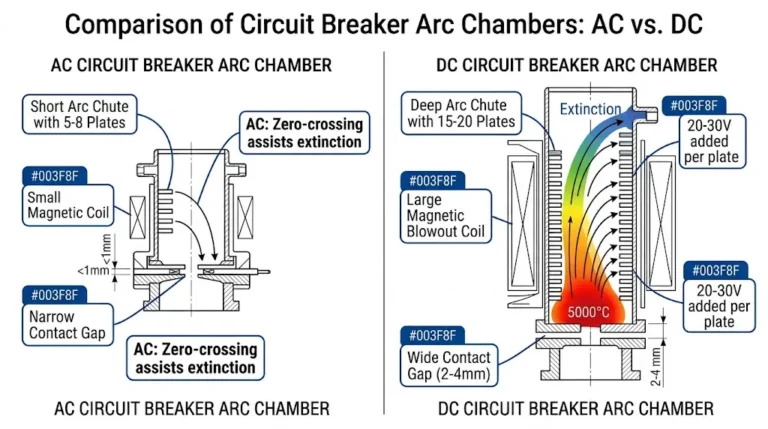
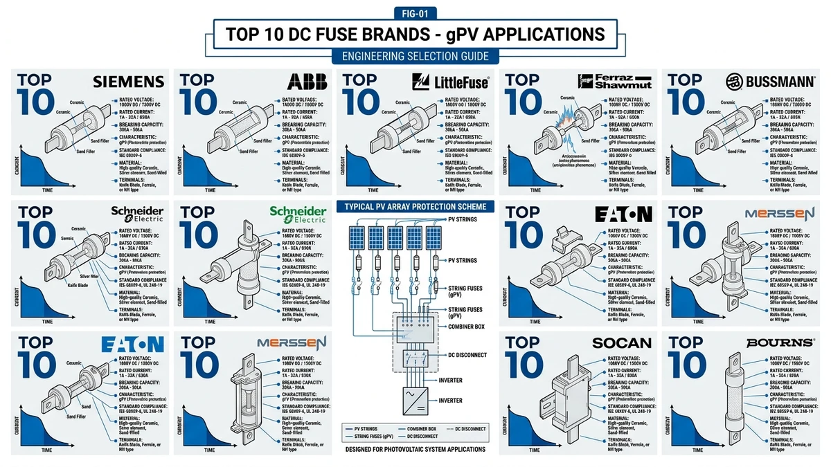
The core difference lies in three engineered characteristics: ceramic-bodied construction with silica sand filler that absorbs arc energy, silver-plated copper elements with controlled M-effect notches that create predictable melting points at 1.45× rated current, and striker pin mechanisms that trigger external disconnect switches when the fuse blows. Unlike standard AC fuses that rely on natural current zero-crossings, gPV fuses must extinguish a continuous DC arc through rapid energy absorption, achieving arc voltage rise rates exceeding 2000 V/ms to force current interruption within 5-8 milliseconds.
DC arcs sustain longer than AC arcs because there’s no natural current zero-crossing. A 1000 VDC-rated fuse uses 38-42 mm of quartz sand column to extinguish arcs, while 1500 VDC versions require 58-65 mm. The sand granule size (typically 0.2-0.4 mm) creates turbulent plasma flow that cools the arc below 3000 K within 2-4 milliseconds. Breaking capacity defines the maximum fault current a fuse can safely interrupt—minimum 20 kA at 1000 VDC for string-level protection, 30 kA at 1500 VDC for utility-scale systems.
The I²t value (ampere-squared seconds) represents thermal energy passed to downstream components during fault clearing. For a 15 A gPV fuse, pre-arcing I²t typically ranges 180-220 A²s (energy absorbed by fuse element before melting), while total I²t reaches 450-550 A²s including the arc phase. Lower I²t protects sensitive bypass diodes in PV modules—a fuse with 600 A²s total I²t may allow diode junction temperatures to exceed 175°C, causing permanent damage.
IEC 60269-6 governs photovoltaic fuse links, specifying voltage ratings up to 1500 VDC, time-current characteristics (gPV curve), and minimum breaking capacity. A certified gPV fuse must pass short-circuit interruption testing at 15 kA rated voltage across 6 samples, overload endurance at 1.5× rated current for 1 hour without melting, and temperature rise testing with terminal temperature ≤75°C above ambient at rated current. TÜV Rheinland and UL 2579 certification marks indicate third-party verification—fuses lacking these certifications may use automotive-grade elements that fail catastrophically above 600 VDC.
For comprehensive DC protection solutions including certified https://sinobreaker.com/dc-fuse/ options, matching fuse specifications to system voltage and fault current levels ensures reliable string-level protection.
[Expert Insight: Field-Proven Selection Criteria]
Fuse voltage rating must be ≥1.25× maximum system voltage to provide safety margin. For a 1000 VDC PV system, use 1250 VDC-rated fuses minimum. At 2500 m altitude, air density drops 25%, reducing dielectric strength—a 1000 VDC fuse must be derated to 850 VDC per IEC 60364-7-712 Annex B. The quartz sand column length directly correlates to voltage rating: 38-42 mm for 1000 VDC, 58-65 mm for 1500 VDC.
Fuse current ratings assume 25°C ambient temperature. At 60°C (typical combiner box interior in summer), apply 0.85× derating factor. A 15 A fuse operates safely at 12.75 A continuous under these conditions. Calculate required fuse rating using NEC 690.9(B): multiply string short-circuit current (Isc) by 1.56. For a string with 10 A Isc, select a 15 A or 16 A fuse. Failure to derate causes nuisance blowing—a 15 A fuse carrying 14 A at 65°C may blow within 200 hours due to cumulative thermal fatigue.
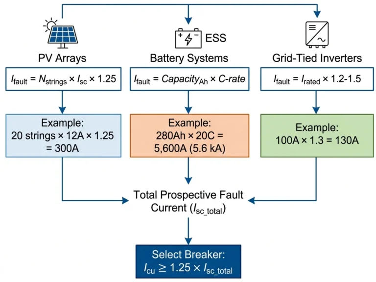
Breaking capacity defines maximum fault current the fuse can safely interrupt. For 1000 VDC systems, specify minimum 20 kA breaking capacity. For 1500 VDC systems, require minimum 30 kA. Calculate available fault current at the fuse location considering PV array configuration and cable impedance. A 10-string array with 10 A Isc per string can theoretically deliver 100 A fault current, but cable resistance typically limits this to 40-60 A. Select breaking capacity ≥1.5× maximum calculated fault current for safety margin.
Selectivity ratio between string fuse and combiner box circuit breaker should be ≥2:1 in current rating to ensure only the faulted string disconnects. A 15 A string fuse paired with a 125 A combiner https://sinobreaker.com/dc-circuit-breaker/ provides 8.3:1 selectivity, preventing array-wide shutdowns. Verify selectivity using manufacturer time-current curves—string fuse must clear in <0.5 seconds while main breaker remains closed during typical fault conditions.

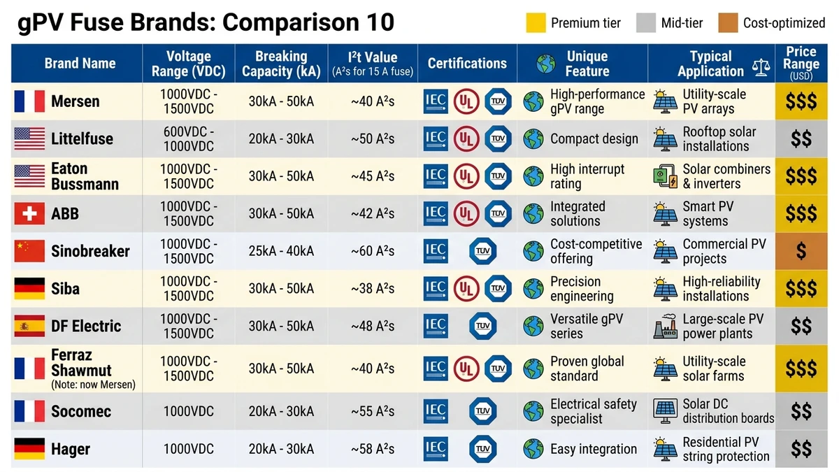
Mersen (France)
Voltage range: 1000-1500 VDC | Breaking capacity: 30 kA at 1500 VDC | I²t (15 A): 480 A²s | Certifications: IEC 60269-6, UL 2579, TÜV | Unique feature: Striker pin indicator for remote monitoring integration | Typical application: Utility-scale PV (>10 MW) | Price: $8-12 USD
Littelfuse (USA)
Voltage range: 1000-1500 VDC | Breaking capacity: 20 kA at 1000 VDC | I²t (15 A): 520 A²s | Certifications: UL 2579, IEC 60269-6 | Unique feature: POWR-GARD series with visual blown indicator | Typical application: Commercial rooftop (500 kW – 5 MW) | Price: $8-11 USD
Eaton Bussmann (USA)
Voltage range: 1000-1500 VDC | Breaking capacity: 30 kA at 1500 VDC | I²t (15 A): 460 A²s | Certifications: UL 2579, IEC 60269-6, CSA | Unique feature: Compact 10×38 mm form factor for high-density combiner boxes | Typical application: String inverter systems (50-250 kW) | Price: $9-12 USD
ABB (Suisse)
Voltage range: 1000 VDC | Breaking capacity: 20 kA at 1000 VDC | I²t (15 A): 540 A²s | Certifications: IEC 60269-6, TÜV | Unique feature: Integrated with ABB’s REACT monitoring system | Typical application: Residential/commercial (5-100 kW) | Price: $7-10 USD
Sinobreaker (China)
Voltage range: 1000-1500 VDC | Breaking capacity: 25 kA at 1500 VDC | I²t (15 A): 490 A²s | Certifications: IEC 60269-6, TÜV Rheinland | Unique feature: Dual-element design for enhanced overload protection | Typical application: Ground-mount solar farms (1-50 MW) | Price: $5-7 USD
Siba (Germany)
Voltage range: 1000-1500 VDC | Breaking capacity: 30 kA at 1500 VDC | I²t (15 A): 470 A²s | Certifications: IEC 60269-6, UL 2579 | Unique feature: Ceramic body for extreme temperature environments (-40°C to +85°C) | Typical application: Desert/arctic installations | Price: $8-11 USD
DF Electric (China)
Voltage range: 1000 VDC | Breaking capacity: 20 kA at 1000 VDC | I²t (15 A): 550 A²s | Certifications: IEC 60269-6, CQC | Unique feature: Cost-optimized for high-volume residential deployments | Typical application: Distributed rooftop (3-10 kW) | Price: $4-6 USD
Ferraz Shawmut (France/USA)
Voltage range: 1000-1500 VDC | Breaking capacity: 30 kA at 1500 VDC | I²t (15 A): 450 A²s | Certifications: UL 2579, IEC 60269-6 | Unique feature: Atdr series with arc-flash reduction technology | Typical application: ESS integration (battery + PV hybrid) | Price: $7-10 USD
Socomec (France)
Voltage range: 1000 VDC | Breaking capacity: 20 kA at 1000 VDC | I²t (15 A): 510 A²s | Certifications: IEC 60269-6, TÜV | Unique feature: Integrated into Socomec combiner boxes with pre-wired terminals | Typical application: Turnkey combiner solutions (100-500 kW) | Price: $6-9 USD
Hager (Germany)
Voltage range: 1000 VDC | Breaking capacity: 20 kA at 1000 VDC | I²t (15 A): 530 A²s | Certifications: IEC 60269-6, VDE | Unique feature: Modular fuse holder system for tool-free replacement | Typical application: Residential/small commercial (5-50 kW) | Price: $5-8 USD
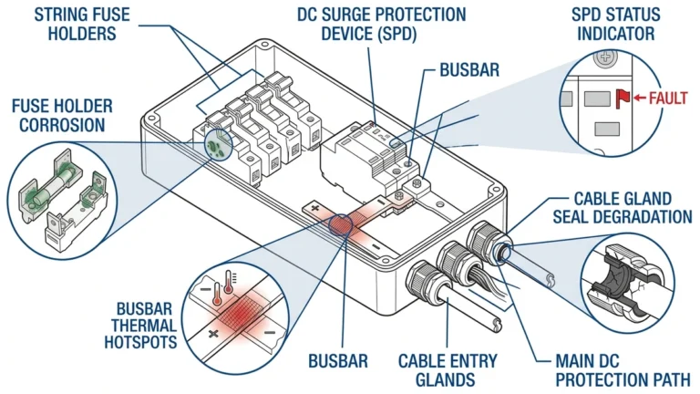
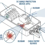
A gPV fuse is only as reliable as its holder. Contact resistance between fuse ferrule and holder clip should be <5 mΩ to prevent hotspots. In a 2024 field audit of 200 combiner boxes in Qinghai Province, 14% of premature fuse failures traced to corroded holders (copper-plated steel) rather than fuse defects. Tin-plated copper holders maintain <3 mΩ resistance after 5000 thermal cycles.
Holder types include DIN rail mount (10×38 mm, 14×51 mm per IEC 60269-6 standard sizes), panel mount requiring IP65-rated enclosure for outdoor use, and PCB mount limited to 32 A for inverter-integrated protection. Quality holders achieve contact resistance below 0.5 mΩ at rated current, while inferior designs can exceed 2.0 mΩ, generating localized heating that accelerates fuse aging.
Combiner box interior temperatures regularly reach 60-70°C in direct sunlight. At 60°C ambient, apply 0.85× derating factor to fuse current rating. A 15 A fuse operates safely at 12.75 A continuous. At 70°C, derating increases to 0.80×, reducing safe continuous current to 12 A.
Manufacturers provide derating curves in datasheets—always verify rather than assume linear derating. Failure to account for temperature causes nuisance blowing. A 15 A fuse carrying 14 A at 65°C may blow within 200 hours due to cumulative thermal fatigue in the fuse element.
Price per fuse (15 A, 1000 VDC, 10×38 mm):
A 5 MW solar farm uses approximately 800 string fuses. Choosing budget fuses saves $4800 upfront but risks higher failure rate (2-3% annual vs 0.2% for premium brands), warranty claims (module manufacturers may void warranties if non-certified fuses are used), and replacement labor ($50-80 per fuse change in remote locations). Total cost of ownership over 25 years typically favors mid-to-premium tier fuses—the $3200 additional upfront investment prevents an estimated $18,000-24,000 in replacement labor and downtime losses.
[Expert Insight: Installation and Maintenance Realities]
Fuse holder terminals require precise torque to prevent arcing. M4 screw terminals need 1.2-1.4 Nm, while M5 terminals require 1.8-2.2 Nm. Over-torquing cracks ceramic fuse bodies, creating internal stress fractures that propagate during thermal cycling. Under-torquing creates micro-arcing that carbonizes insulation and increases contact resistance above 10 mΩ, generating hotspots.
Use a calibrated torque screwdriver—beam-type or click-type with ±5% accuracy. Apply thread-locking compound (Loctite 243 or equivalent) on outdoor installations to prevent vibration loosening. Re-torque connections during first annual inspection, as initial thermal cycling can relax terminal pressure.
Combiner boxes housing gPV fuses must meet IP65 minimum—dust-tight and protected against water jets from any direction. Use polycarbonate or powder-coated steel enclosures with UV-resistant properties. Ventilation requires passive vents with stainless steel mesh (0.5-1.0 mm openings) to prevent insect ingress while allowing heat dissipation.
In coastal environments subject to salt fog, use stainless steel (316L grade) fuse holders and conformal-coated PCBs to prevent galvanic corrosion. Aluminum enclosures require anodizing or powder coating—bare aluminum corrodes rapidly in marine atmospheres, increasing contact resistance and creating failure points.
Inspect gPV fuses every 12 months using three methods:
Replace fuses after any fault event, even if they appear intact. Internal fuse element may have micro-cracks that cause delayed failure under normal load.
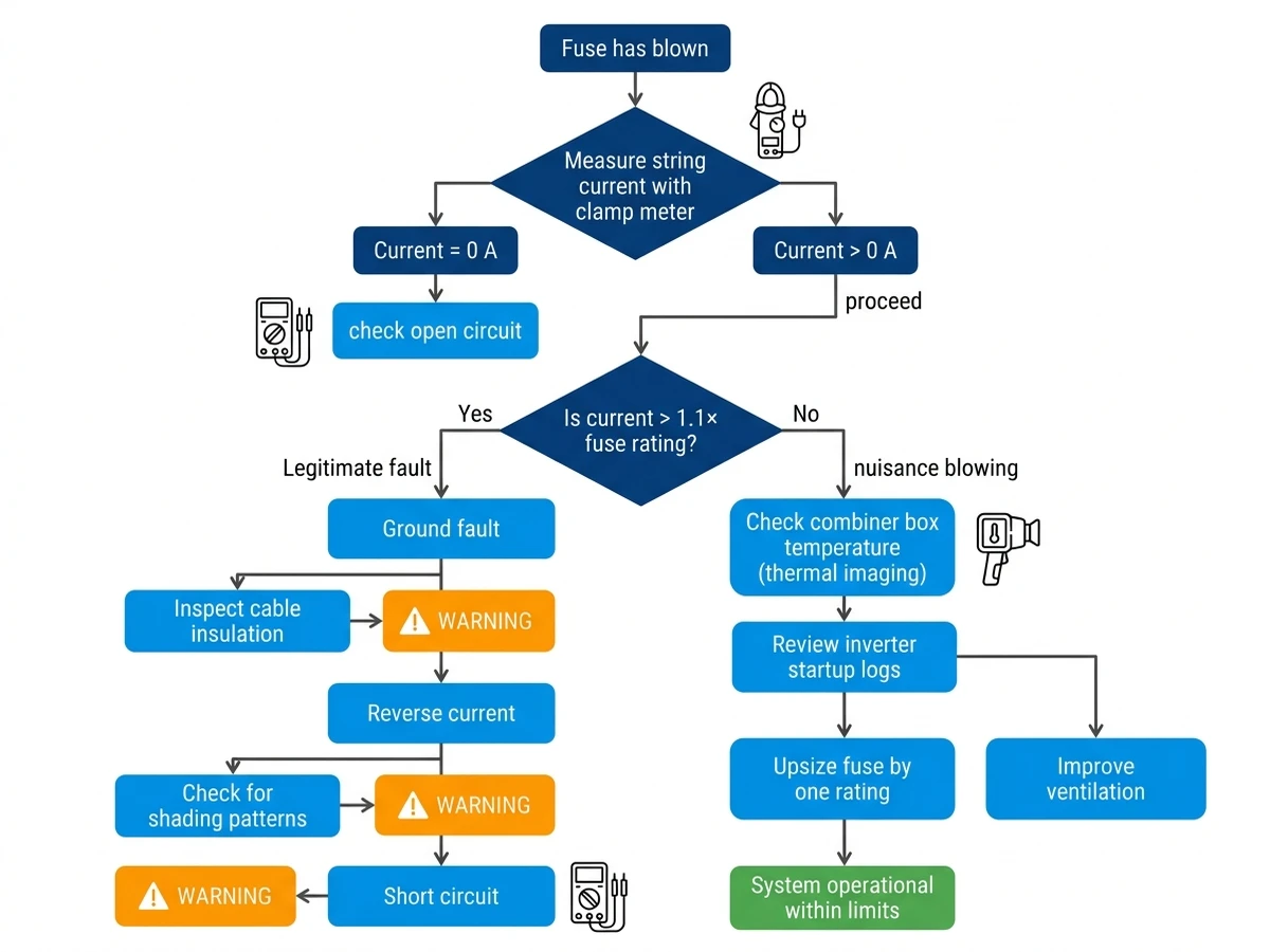
Nuisance blowing occurs when fuses open without actual faults. Cause 1: Inrush current during inverter startup reaches 5-8× rated current for 50-100 ms, exceeding fuse I²t tolerance. Cause 2: Ambient temperature exceeds derating threshold—a 15 A fuse in a 70°C combiner box effectively operates as a 12 A fuse. Solution: Upsize fuse by one rating (15 A → 20 A) if string Isc allows, or improve combiner box ventilation to reduce interior temperature.
Legitimate faults include ground faults (insulation breakdown in cable or module), reverse current (shaded string backfeeds into healthy strings), and short circuits (internal module failure or rodent damage). Use a clamp meter to measure string current before replacing fuse—persistent overcurrent indicates unresolved fault requiring further investigation.
Counterfeit gPV fuses represent an estimated 8-12% of global market volume, lacking proper arc-quenching fill. Weight test: Genuine 15 A fuse weighs 18-22 g; counterfeits weigh 12-16 g due to insufficient quartz sand. X-ray inspection reveals voids in sand column or incorrect element geometry—genuine fuses show uniform sand density and centered fuse element.
Certification verification: Cross-check serial numbers with manufacturer database via website or phone. Counterfeits often use recycled serial numbers or fabricated certification marks. A counterfeit fuse may pass low-current tests but explode catastrophically at rated breaking capacity, ejecting molten metal and igniting nearby components.
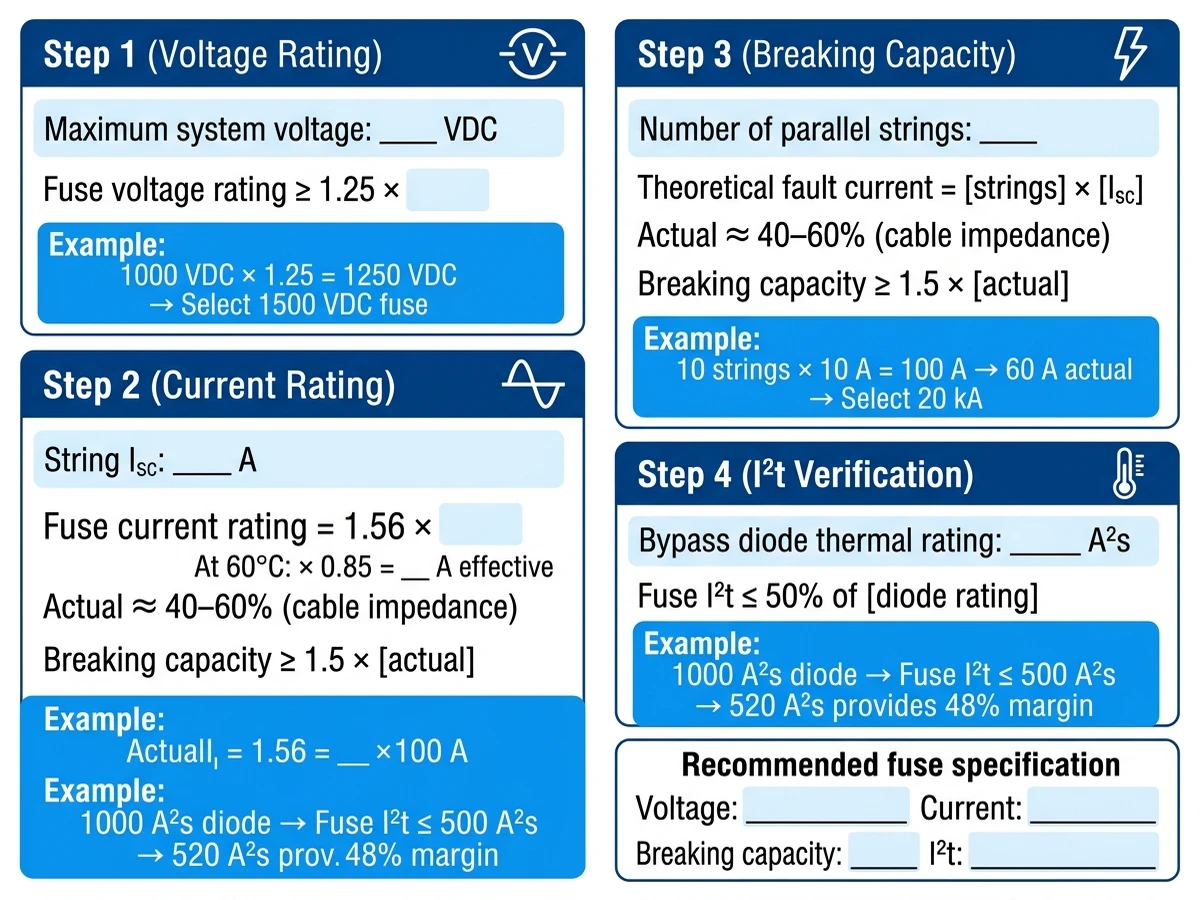
Match fuse specifications to system parameters using four steps:
Step 1: Voltage Rating
Select fuse voltage rating ≥1.25× maximum system voltage. For a 1000 VDC system, use 1250 VDC-rated fuses minimum. Example: System with 20 modules × 50 VDC = 1000 VDC maximum → select 1250 VDC or 1500 VDC fuses.
Step 2: Current Rating
Calculate using NEC 690.9(B): Fuse rating = 1.56× string Isc. For a string with 10 A Isc, required fuse rating = 1.56 × 10 A = 15.6 A → select 16 A fuse (next standard size). Verify derating: At 60°C ambient, 16 A × 0.85 = 13.6 A effective rating, still above 10 A Isc.
Step 3: Breaking Capacity
Calculate maximum available fault current at fuse location. For a 10-string array with 10 A Isc per string, theoretical fault current = 100 A. Cable impedance typically limits this to 40-60 A. Select breaking capacity ≥1.5× maximum fault current: 60 A × 1.5 = 90 A minimum, but use 20 kA standard rating for safety margin.
Step 4: I²t Value
Verify I²t ≤50% of bypass diode thermal rating. Typical bypass diodes tolerate 1000-1200 A²s. For a 16 A fuse with 520 A²s total I²t, protection margin = (1000 – 520) / 1000 = 48% safety factor.
Practical example for 10-string combiner box (each string 10 A Isc, 1000 VDC):
Verify selectivity using manufacturer time-current curves—string fuse must clear in <0.5 seconds at 1.35× rating while main fuse remains closed.
Choosing the right gPV fuse brand balances upfront cost, certification credibility, and long-term reliability. Premium brands like Mersen and Bussmann offer proven performance in harsh environments with extensive field data, while mid-tier options like Sinobreaker provide IEC-certified protection at competitive prices for large-scale deployments. Always verify third-party certifications (TÜV Rheinland, UL), calculate proper derating factors for local climate conditions, and source from authorized distributors to avoid counterfeit products that compromise system safety.
For comprehensive DC protection solutions including certified gPV fuses, https://sinobreaker.com/dc-fuse/ offers IEC 60269-6 compliant options with breaking capacities up to 30 kA at 1500 VDC. Integrate string-level fuse protection with https://sinobreaker.com/pv-combiner-box/ solutions featuring pre-wired terminals and IP65-rated enclosures to match components to your specific system voltage, fault current, and environmental requirements.
gPV fuses are specifically engineered for photovoltaic systems with enhanced DC arc interruption capability up to 1500 VDC, certified under IEC 60269-6 with time-current characteristics optimized for solar string protection and selectivity coordination with upstream devices.
Multiply the PV module’s short-circuit current (Isc) by 1.56 per NEC 690.9(B) requirements, then apply temperature derating based on combiner box ambient conditions—a string with 10 A Isc in a 60°C environment requires approximately 18 A rated fuse capacity.
Automotive fuses lack the quartz sand arc-quenching medium and voltage rating needed for DC systems above 600 VDC, and will fail catastrophically during fault conditions due to insufficient breaking capacity and improper time-current characteristics for PV applications.
Inspect gPV fuses annually using visual checks for discoloration or cracks, thermal imaging to detect hotspots above 15°C ambient differential, and continuity testing with low-current ohmmeters—replace any fuse after a fault event regardless of visual appearance.
I²t (ampere-squared seconds) represents thermal energy passed to downstream components during fault clearing—lower I²t values between 450-500 A²s for 15 A fuses better protect sensitive bypass diodes from exceeding their thermal limits during short-circuit events.
Mid-tier Chinese brands with IEC 60269-6 and TÜV Rheinland certification demonstrate comparable breaking capacity and I²t characteristics to European brands, though premium manufacturers may offer longer field-proven track records in extreme environmental conditions.
Fuse current ratings assume 25°C ambient temperature and require approximately 0.85× derating at 60°C typical combiner box interior temperatures—a 15 A fuse should carry no more than 12.75 A continuous in hot climates to prevent thermal fatigue.
Authority Reference: International Electrotechnical Commission (IEC), “IEC 60269-6:2010+AMD1:2018 – Low-voltage fuses – Part 6: Supplementary requirements for fuse-links for the protection of solar photovoltaic energy systems,” https://webstore.iec.ch/publication/1242