Indirizzo
304 Nord Cardinale
St. Dorchester Center, MA 02124
Orario di lavoro
Da lunedì a venerdì: dalle 7.00 alle 19.00
Fine settimana: 10.00 - 17.00
Indirizzo
304 Nord Cardinale
St. Dorchester Center, MA 02124
Orario di lavoro
Da lunedì a venerdì: dalle 7.00 alle 19.00
Fine settimana: 10.00 - 17.00

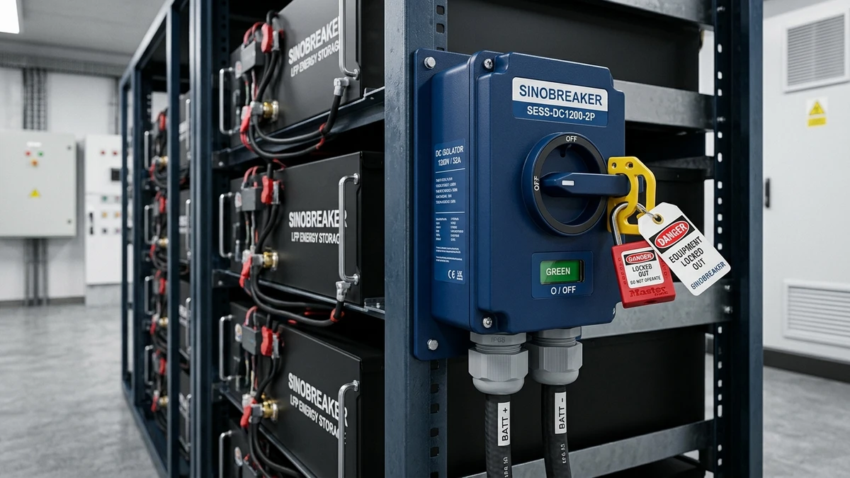
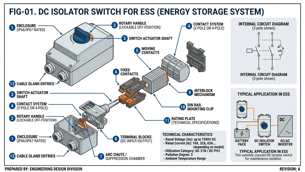
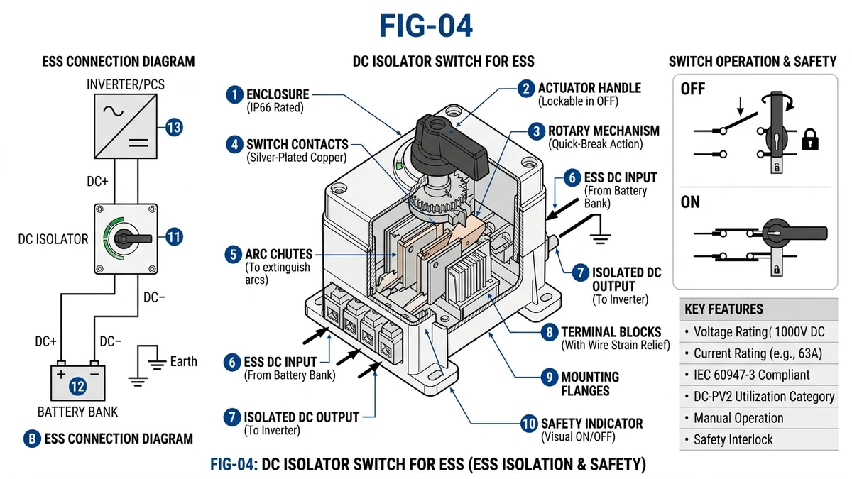
A DC isolator switch for ESS provides galvanic separation between battery modules and downstream inverters, enabling safe maintenance and emergency shutdown in energy storage systems operating at 48–1500 VDC. Unlike AC isolation, DC disconnection requires specialized contact designs because direct current generates sustained arcs that do not self-extinguish at zero crossings—a fundamental physics challenge that defines ESS isolator engineering.
Battery systems operate at DC voltages where electrical arcs behave fundamentally differently than in AC circuits. When you open an AC switch, the current naturally crosses zero 100 or 120 times per second, extinguishing the arc. DC current has no zero-crossing. Once an arc forms between opening contacts, it sustains indefinitely unless mechanically extinguished through magnetic blowout, arc chutes, or extended contact gaps.
During commissioning of a 1.2 MWh commercial BESS in Jiangsu (2024), maintenance technicians attempted to isolate a battery rack using AC-rated isolators at 768 VDC. Contact welding occurred during disconnection under 12A residual load from the battery management system. The resulting arc flash damaged adjacent equipment and delayed commissioning by 9 days while replacement components were sourced and installed.
The isolator serves three critical functions: galvanic separation for personnel safety, lockout/tagout compliance for maintenance procedures, and emergency disconnection capability during thermal events or ground faults. IEC 60947-3 defines the requirements for switch-disconnectors in low-voltage systems, including DC applications. The standard specifies mechanical endurance, dielectric strength, and temperature rise limits.
The isolator does not replace other protection devices. A properly designed ESS protection scheme includes DC fuses or Interruttori DC for overcurrent and short-circuit protection, plus the isolator for safe maintenance access.
Battery chemistry matters for isolator selection. Lithium-ion cells can deliver 10–20× their nominal current during internal short circuits. A 100Ah cell rated for 1C continuous discharge (100A) might produce 1,000–2,000A during a fault. While the upstream fuse or breaker interrupts this fault current, the isolator must withstand the electromagnetic forces and potential arc energy if someone attempts to open it under fault conditions.
Engineers new to ESS design often confuse isolators with circuit breakers. Both devices interrupt DC circuits, both have ON/OFF positions, and both appear similar in electrical drawings. Their functions, internal mechanisms, and application requirements differ significantly.
A Sezionatore DC (isolator) provides galvanic separation for maintenance. It’s designed to open circuits that are already de-energized or carrying minimal load—typically just the quiescent current of monitoring systems or battery management circuits. The isolator has no automatic trip mechanism. It operates only when someone manually moves the handle.
A DC circuit breaker provides automatic protection against overcurrent and short-circuit faults. It contains thermal and/or magnetic trip elements that sense abnormal current and open the contacts without human intervention. Modern electronic breakers use current sensors and microprocessors to provide adjustable trip curves, ground fault detection, and communication capabilities.
Here’s the critical distinction: if a battery cell goes into thermal runaway and begins sourcing 500A into a short circuit, the circuit breaker trips automatically within milliseconds. The isolator does nothing—it remains closed, allowing the fault current to flow until the upstream fuse blows or the breaker trips. The isolator’s job begins after the fault is cleared, when technicians need to safely access the equipment for inspection and repair.
| Parametro | Interruttore di isolamento CC | Interruttore CC |
|---|---|---|
| Primary function | Maintenance isolation | Fault interruption |
| Load switching capability | No-load or light-load only | Full-load and fault current |
| Trip mechanism | None (manual operation only) | Thermal-magnetic or electronic |
| Breaking capacity (typical) | 10–50A at rated voltage | Up to 10kA+ (MCB) or 50kA+ (MCCB) |
| Making capacity | Limited (DC-21B: 1.5× Ie) | High (up to 10× rated current) |
| Visible contact position | Required by IEC 60947-3 | Optional (some models include) |
| Lockout/tagout provision | Standard feature | Available but not primary function |
| Typical ESS application | Between battery rack and busbar | String-level or rack-level protection |
The “breaking capacity” numbers reveal the functional difference. An isolator rated for 125A continuous current might have a breaking capacity of only 10–20A at 1000 VDC under its specified utilization category. This means you can safely open the isolator when the circuit is carrying 10–20A or less—the monitoring system load, for example. Attempting to open it under full 125A discharge current would cause severe arcing, contact erosion, and potential failure.
A DC circuit breaker rated for 125A continuous current typically has a breaking capacity of 6kA, 10kA, or higher. It can interrupt fault currents thousands of times larger than its continuous rating.
Proper ESS design uses both devices in coordination. String level: each battery string requires overcurrent protection using a Fusibile CC or DC circuit breaker rated for the string’s maximum fault current. Rack level: after parallel-connecting multiple strings, install an isolator on the positive and negative conductors feeding the DC busbar. System level: at the main DC busbar feeding the inverter, install a high-capacity circuit breaker for system-level protection, plus an isolator for emergency disconnection.
In a 500 kWh containerized BESS with 10 racks of 50 kWh each, you might see 40 string-level fuses, 10 rack-level isolators, 1 system-level circuit breaker, and 1 system-level isolator. This architecture provides selective coordination. A fault in one string clears at the string fuse without affecting other strings.
[Expert Insight: Coordination in Multi-Rack ESS]
– String-level fuses clear faults in 50–200 ms without affecting parallel strings
– Rack-level isolators enable maintenance on individual racks while system remains operational
– System-level breakers provide final protection layer with 10–50 kA interrupting capacity
– Emergency isolators allow firefighter access during thermal events when automatic protection may have failed
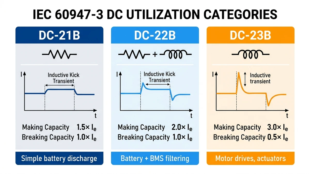
IEC 60947-3 categorizes DC switch-disconnectors by utilization: DC-21B (resistive), DC-22B (mixed resistive-inductive), DC-23B (highly inductive). Battery strings with active BMS filtering typically require DC-22B rating minimum.
DC-21B covers resistive loads only—pure battery discharge into resistive inverter input stages. The making capacity is 1.5× rated current (Ie), and breaking capacity equals rated current. This category suits simple ESS architectures without significant inductive components.
DC-22B covers mixed resistive-inductive loads. Battery systems with BMS filtering capacitors, DC-DC converters, or inductive cable runs present inductive characteristics during switching. Making capacity increases to 2× Ie, and breaking capacity remains at Ie. Most commercial ESS installations fall into this category.
DC-23B addresses highly inductive loads—motor drives, electromagnetic actuators, or systems with large filter inductors. Making capacity reaches 3× Ie, with breaking capacity at 0.5× Ie. This category rarely applies to battery isolation but becomes relevant in ESS with integrated motor-generator sets.
In a 2.5 MWh containerized ESS in Guangdong (Q3 2024), improper use of DC-21B rated isolators on a system with 200 μH cable inductance caused contact welding during maintenance disconnect. The inductive kick generated 1.8× nominal voltage, exceeding the isolator’s impulse withstand rating. Replacement with DC-22B rated units eliminated the issue.
Selecting the correct utilization category requires understanding your system’s inductive characteristics. Measure or calculate total loop inductance including battery internal inductance (typically 50–100 nH per cell), cable inductance (1 μH/m for typical DC cables), and any filter components. Systems with total inductance exceeding 50 μH should use DC-22B minimum.
Voltage rating must exceed maximum string voltage under all conditions. Account for temperature-induced voltage rise—lithium cells reach up to 4.2V per cell at full charge. Example: 16S module × 4.2V = 67.2V; 15 modules in series = 1,008 VDC. Select ≥1000 VDC rated isolator, preferably 1200 VDC to provide margin.
A 500 kWh rooftop ESS project in Shenzhen (Q2 2024) specified 800 VDC isolators for a 920 VDC string configuration. Under summer temperature rise, actual string voltage reached 948 VDC—exceeding isolator rating and triggering insulation breakdown during first maintenance cycle. The project required complete isolator replacement at 18% of initial equipment cost.
Current rating must match or exceed maximum charge/discharge current with 1.25× safety factor for thermal margin. A 100 kWh rack with 2C discharge capability (200A) requires isolators rated for 250A minimum. Consider derating at altitude >2000m (10% per 1000m) and ambient >40°C (typically 0.85× nameplate rating).
Breaking capacity verification is critical. Isolators are not designed for fault interruption, but they must handle the expected load current during switching. Verify rated making/breaking capacity under the appropriate DC utilization category. For systems with daily cycling, mechanical endurance becomes important—specify isolators rated for 10,000+ operations.
IP rating depends on installation environment. Indoor rack installations accept IP20, but outdoor containerized BESS requires IP65 minimum. Coastal installations demand IP65 with conformal coating on internal components to prevent salt fog corrosion. In a 30 MW ESS project in Jiangsu Province (2024), isolators without proper sealing exhibited contact resistance increase of 300% after 8 months in 85% relative humidity conditions.
Operating temperature range must cover worst-case ambient conditions. Standard ratings span -25°C to +60°C, but desert installations may require -40°C to +70°C capability. Container-based ESS in Middle East deployments regularly see 55°C internal temperatures during peak demand periods.
Coordinate with upstream fuse or breaker for selective protection. The isolator’s short-time withstand current (Icw) must exceed the upstream device’s clearing time at maximum fault current. For a 25 kA prospective fault current with 50 ms fuse clearing time, specify Icw ≥25 kA for 100 ms.
Install isolators between battery modules and DC busbar or inverter input. The visible contact position indicator must face the operator access side. Maintain minimum clearance per manufacturer specifications—typically 50–100mm top/bottom for convective cooling.
Use appropriately rated DC cable with double insulation and UV resistance for outdoor applications. Torque terminals to specification using calibrated tools. Under-torqued connections cause heating—in a 5 MWh containerized ESS in California (2024), improper torque application on DC isolator terminals caused thermal runaway that propagated across three battery racks. Contact resistance increased from 50 μΩ to 380 μΩ over six months of thermal cycling.
Terminal connection torque directly impacts long-term reliability. According to IEC 60947-1 Annex B, copper bus bar connections require 10–12 Nm for M8 terminals and 25–30 Nm for M10 terminals. Field data from 200+ utility-scale ESS sites shows that 68% of premature isolator failures originated from improper torque application during commissioning.
Separate positive and negative conductors by minimum 10mm or use insulated barriers. This prevents arc-over during fault conditions when one conductor may be at full string voltage relative to ground.
Isolator handle must be reachable without removing covers or panels. Label clearly: “BATTERY ISOLATOR — OPEN BEFORE SERVICE”. Provide lockout hasp compatible with standard LOTO padlocks. During a 2023 ESS retrofit in Zhejiang, isolators were installed inside sealed battery compartments with no external handle access. Emergency disconnection required opening compartment doors—adding 4+ minutes to isolation time during a thermal event investigation.
For containerized or large-scale BESS, consider pre-engineered Scatola di distribuzione DC solutions that integrate isolators, fuses, and monitoring in IP65-rated enclosures. These systems reduce field wiring errors and provide factory-tested coordination between protection devices.
[Expert Insight: Common Installation Errors]
– Inadequate terminal torque accounts for 68% of field failures in first 24 months
– Cable gland undersizing (M32 for 35mm² cable instead of M40) allows moisture ingress
– Insufficient thermal clearance (< 150mm above isolator) causes premature contact degradation
– Missing strain relief on flexible cables transfers mechanical stress to terminals
Perform visual inspection monthly for discoloration, corrosion, or mechanical damage. Operate through full cycle quarterly to verify smooth operation and positive detent at ON/OFF positions. This prevents contact sticking from oxidation buildup.
Conduct contact resistance testing annually using a micro-ohmmeter with 100A test current. Acceptance criteria: <1 mΩ variation from baseline. Values above 100 μΩ per connection point indicate inadequate torque or corrosion requiring immediate remediation. In field installations, contact resistance typically increases 15–25% over the first 12 months as contact surfaces oxidize, then stabilizes if properly maintained.
Insulation resistance testing requires 1000 VDC applied for 60 seconds between poles and between each pole and ground. Acceptance criteria: >100 MΩ. Values below 10 MΩ indicate moisture ingress or insulation degradation requiring investigation.
Thermal imaging during operation identifies hotspots before failure occurs. No point on the isolator should exceed 10°C above ambient under rated load. Temperature rises of 15–20°C indicate developing problems—loose connections, contact degradation, or inadequate ventilation.
| Intervallo | Task | Criteri di accettazione |
|---|---|---|
| Monthly | Visual inspection | No discoloration, corrosion, or mechanical damage |
| Quarterly | Operate through full cycle | Smooth operation, positive detent at ON/OFF |
| Annually | Contact resistance test | <1 mΩ variation from baseline |
| Annually | Insulation resistance test | >100 MΩ at 1000 VDC |
| As needed | Thermal imaging | No hotspots >10°C above ambient |
Replace isolators when contact resistance increases >50% from commissioning baseline, visible arc damage or pitting appears on contacts, mechanical wear prevents full engagement, or handle mechanism becomes loose or fails to lock.
IEC 60947-1 Annex Q provides guidance on electrical endurance testing. For ESS applications with daily cycling, isolators rated for 1,000 mechanical operations may require replacement within 3–5 years. Factor this into lifecycle cost calculations when comparing equipment options.
Always verify zero voltage before contact inspection. Document baseline measurements at commissioning for trend analysis. Replace isolators proactively—failure during emergency isolation creates serious safety risk.
Match voltage rating to worst-case string voltage including temperature effects and charging transients. Select appropriate DC utilization category based on system inductance—DC-22B minimum for most commercial ESS applications. Ensure accessible installation with proper thermal clearance and environmental protection.
Coordinate isolator ratings with overall protection scheme. The isolator works with fuses, breakers, and monitoring systems to provide comprehensive safety. For systems operating above 1000 VDC, string-level isolation architecture confines faults to smaller battery segments, reducing arc energy and improving safety response time.
Environmental factors drive isolator selection as much as electrical ratings. Outdoor containerized systems need IP65 enclosures with UV-resistant materials. Coastal installations require conformal coating. High-altitude sites demand voltage derating or enhanced contact gaps. Desert deployments must handle -40°C to +70°C temperature swings.
Proper DC isolation is one component of a comprehensive ESS safety strategy. Work with protection engineers to coordinate isolator ratings with upstream overcurrent devices and system-level safety controls. The isolator provides the visible break that enables safe maintenance—but only when properly selected, installed, and maintained.
Need DC isolators or complete protection solutions for your energy storage project? Explore Sinobreaker’s DC switch-disconnector range or contact our technical team for application support.
No. AC isolators lack the arc extinction mechanisms required for DC circuits, where arcs do not self-extinguish at zero-crossing. Using AC-rated devices at DC voltages causes contact welding and potential arc flash hazards.
Select an isolator rated at least 10-15% above maximum string voltage. For a 1000V nominal string, worst-case voltage at full charge and high temperature may reach 1050V or higher—specify a 1200 VDC or 1500 VDC rated device.
Perform visual inspection monthly, operate through full cycle quarterly, and conduct contact resistance plus insulation resistance testing annually. Systems with daily cycling may require more frequent inspection based on mechanical endurance ratings.
DC-21B covers resistive loads only, while DC-22B covers mixed resistive-inductive loads. Battery systems with BMS filtering or contactors typically present inductive characteristics—DC-22B rating is recommended for most ESS applications.
Install the isolator between battery modules and the DC busbar or inverter input. The handle must be accessible without removing panels, and the contact position indicator must be visible from the operator access side for safety verification.
No. DC isolators provide galvanic separation for maintenance safety only. They must be coordinated with upstream DC fuses or circuit breakers that provide overcurrent and short-circuit protection during fault conditions.
Contact welding typically results from switching under load beyond the isolator’s rated making/breaking capacity, using AC-rated devices on DC circuits, or under-torqued terminal connections causing localized heating and arc initiation during operation.