Indirizzo
304 Nord Cardinale
St. Dorchester Center, MA 02124
Orario di lavoro
Da lunedì a venerdì: dalle 7.00 alle 19.00
Fine settimana: 10.00 - 17.00
Indirizzo
304 Nord Cardinale
St. Dorchester Center, MA 02124
Orario di lavoro
Da lunedì a venerdì: dalle 7.00 alle 19.00
Fine settimana: 10.00 - 17.00

The 40 amp DC circuit breaker occupies a critical middle ground in DC electrical protection—large enough for significant solar charge controllers, RV main feeds, and marine equipment, yet small enough for cost-effective residential installations. This amperage rating appears frequently in renewable energy and mobile power systems, making proper sizing and application knowledge essential.
This comprehensive guide explores load calculation methods, wire sizing requirements, voltage drop considerations, and application-specific installation techniques for 40A DC breakers in solar photovoltaic, recreational vehicle, and marine electrical systems.
The 40A threshold represents typical capacity boundaries for several applications:
Solar Charge Controllers:
– 30A MPPT controller with 125% NEC safety factor: 37.5A → 40A breaker
– 2400W solar array at 48V: 2400W ÷ 48V = 50A × 0.8 efficiency = 40A output
– 1600W array at 48V: 33A × 1.25 = 41A → 40A minimum
RV Electrical Systems:
– 12V converter output: 480W ÷ 12V = 40A
– Main 12V distribution feed from battery
– Large appliance circuits (refrigerator, air conditioning fan)
Marine Applications:
– Freshwater pressure pump: 300W ÷ 12V = 25A × 1.25 = 31A → 40A breaker
– Navigation electronics suite: Combined 400W load
– Bow thruster control circuit (low-duty cycle)
Industrial/Telecom:
– 48V telecom equipment racks: 1500-1800W typical
– DC UPS systems output circuits
– Battery backup distribution
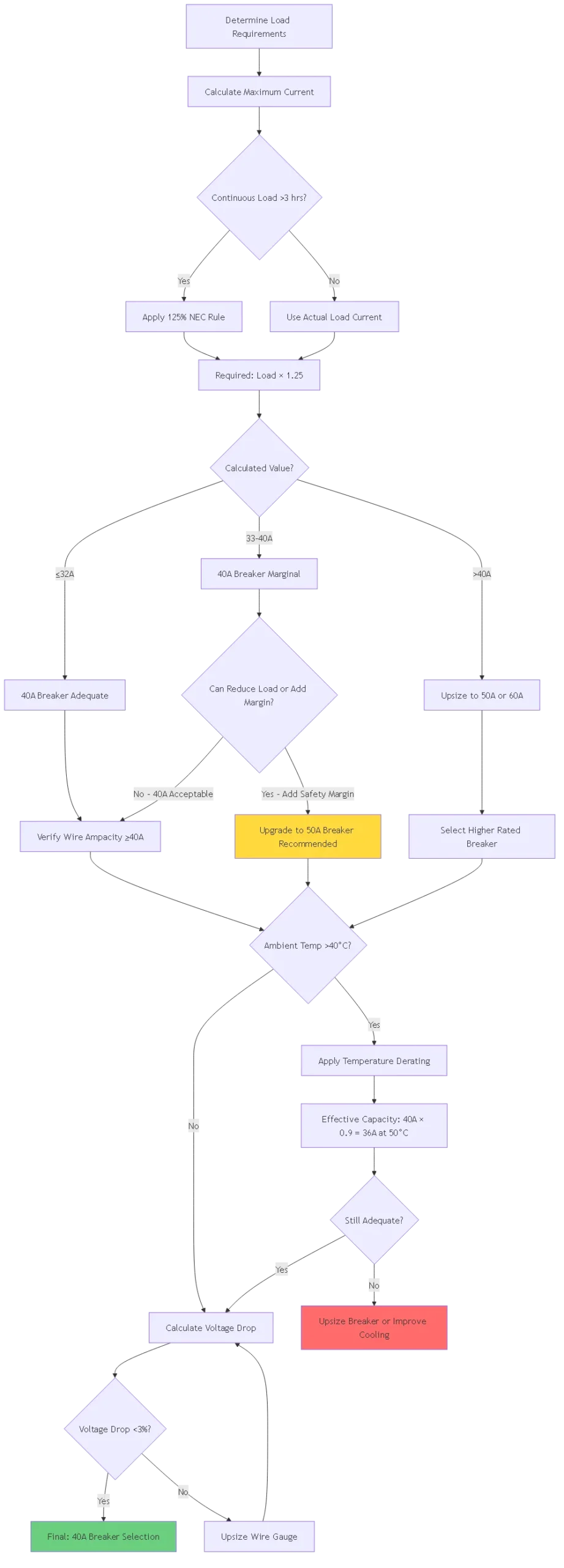
NEC Article 210.19(A)(1) & 690.8(B) Requirements:
For loads operating continuously (≥3 hours), circuit protection must be rated at minimum 125% of the continuous current:
Required Breaker Rating = Continuous Load Current × 1.25Example 1: Solar Charge Controller Controller output: 30A continuous Required breaker: 30A × 1.25 = 37.5A Select: 40A breaker (next standard size up)
Example 2: RV Water Pump Pump current: 25A intermittent (<10 minutes per use) Required breaker: 25A (no 125% factor for intermittent) Select: 30A or 40A breaker (40A provides margin)
Why 125% Safety Factor:
1. Heat accumulation over extended operation
2. Ambient temperature variations affecting trip point
3. Aging components (trip point drift lower)
4. Simultaneous loads on shared conductors
5. Voltage sag increasing current draw
Method 1: Nameplate Rating (Conservative)
Use equipment nameplate specifications:
Example: Solar Inverter
Nameplate: "Max DC Input Current: 35A at 48V"
Calculation: 35A × 1.25 = 43.75A
Select: 50A breaker
Note: Provides safety margin beyond 40A option
Method 2: Measured Current (Accurate)
Use DC clamp meter under actual operating conditions:
Procedure:
1. Clamp meter around positive conductor
2. Operate equipment at maximum expected load
3. Record peak current for 10 minutes
4. Use highest observed value × 1.25
Example Measurement: Peak: 32A observed Required breaker: 32A × 1.25 = 40A (exactly matched)
Method 3: Power-Based Calculation
Calculate from wattage and voltage:
Current (A) = Power (W) ÷ Voltage (V)Example: 48V Solar System Array power: 2000W System voltage: 48V nominal (44V low voltage cutoff) Worst-case current: 2000W ÷ 44V = 45.5A Required breaker: 45.5A × 1.25 = 56.9A → Select 60A
Note: 40A insufficient for this application
Critical Voltage Consideration:
Always calculate current at LOWEST system voltage:
❌ WRONG Calculation:
2000W ÷ 48V = 41.7A × 1.25 = 52A → 60A breaker
✓ CORRECT Calculation: 48V LiFePO4 battery: – Nominal: 51.2V (16 cells × 3.2V) – Discharge cutoff: 40V (16 cells × 2.5V)
Current at cutoff: 2000W ÷ 40V = 50A Required: 50A × 1.25 = 62.5A → 70A breaker minimum
Using 40A breaker would trip prematurely as battery depletes!
Multiple loads on same circuit require summation:
Example: RV 12V Distribution Circuit
- Interior LED lights: 8A
- Water pump: 25A (when running)
- Refrigerator: 12A
- Furnace fan: 8A (when running)
Worst-case scenario (all on): Total: 8 + 25 + 12 + 8 = 53A
Reality check – Not all operate simultaneously: – Lights: Always possible – Water pump: Intermittent (1-2 min bursts) – Refrigerator: 30% duty cycle – Furnace: Occasional
Realistic simultaneous load: Lights (8A) + Refrigerator (12A) + one other (25A) = 45A Required: 45A × 1.25 = 56.25A → 60A breaker
Alternative: 40A breaker with load management (prevent simultaneous operation)
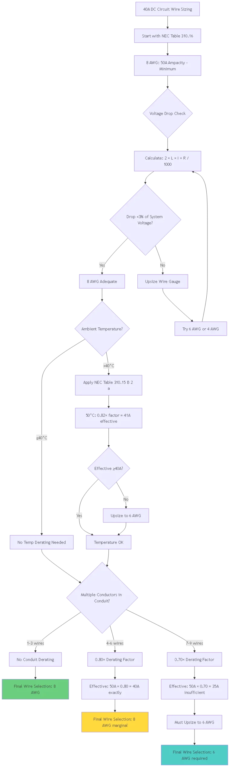
NEC Table 310.16 (75°C Copper Conductor, 30°C Ambient):
| Dimensione del filo | Ampacità | Suitable for 40A Breaker? | Note |
|---|---|---|---|
| 12 AWG | 25A | ❌ NO | Undersized – fire hazard |
| 10 AWG | 35A | ❌ NO | Below 40A requirement |
| 8 AWG | 50A | ✅ YES | Minimum size for 40A breaker |
| 6 AWG | 65A | ✅ YES | Preferred (25% margin) |
| 4 AWG | 85A | ✅ YES | Oversized (long runs, future) |
Critical Rule: Wire ampacity must equal or exceed breaker rating.
Why 8 AWG Minimum:
Breaker rating: 40A
Wire must carry: ≥40A continuously
8 AWG capacity: 50A (meets requirement with 25% margin)
10 AWG capacity: 35A (FAILS - breaker won't protect wire!)
At DC voltages (especially 12V), voltage drop significantly impacts performance:
Formula della caduta di tensione:
Voltage Drop (V) = 2 × Length (ft) × Current (A) × Wire Resistance (Ω/1000ft) / 1000Acceptable Drop Limits: – Feeders: 2% maximum (NEC 215.2(A)(1)) – Branch circuits: 3% maximum (NEC 210.19(A)) – Combined: 5% maximum total system
Esempio di calcolo:
Application: 48V Solar Charge Controller
Current: 40A
Distance: 15 feet from battery to controller
Wire: 8 AWG copper (0.628Ω per 1000 ft)
Drop = (2 × 15 × 40 × 0.628) / 1000 = 0.754V Percentage: 0.754V / 48V = 1.57% (ACCEPTABLE)
If using 10 AWG (1.0Ω per 1000 ft): Drop = (2 × 15 × 40 × 1.0) / 1000 = 1.2V Percentage: 1.2V / 48V = 2.5% (marginal, but acceptable for this circuit)
12V System Example (Voltage Drop Critical):
Application: RV 12V Main Feed
Current: 40A
Distance: 20 feet
Wire: 8 AWG (0.628Ω per 1000 ft)
Drop = (2 × 20 × 40 × 0.628) / 1000 = 1.00V Percentage: 1.00V / 12V = 8.3% (EXCESSIVE!)
Solution – Upsize to 4 AWG (0.249Ω per 1000 ft): Drop = (2 × 20 × 40 × 0.249) / 1000 = 0.40V Percentage: 0.40V / 12V = 3.3% (acceptable)
Conclusion: 12V systems require larger wire than 48V for same power!
| Tensione del sistema | Attuale | Max Distance for 3% Drop | Minimum Wire Size |
|---|---|---|---|
| 12V | 40A | 5 feet | 8 AWG |
| 12V | 40A | 10 feet | 6 AWG |
| 12V | 40A | 20 feet | 4 AWG |
| 24V | 40A | 10 feet | 8 AWG |
| 24V | 40A | 20 feet | 6 AWG |
| 24V | 40A | 40 feet | 4 AWG |
| 48V | 40A | 20 feet | 8 AWG |
| 48V | 40A | 40 feet | 6 AWG |
| 48V | 40A | 80 feet | 4 AWG |
Approfondimento chiave: Higher voltage systems tolerate longer wire runs before requiring upsizing.
Ambient Temperature Correction Factors (NEC Table 310.15(B)(2)(a)):
| Ambient Temp | Correction Factor | 8 AWG Effective Capacity |
|---|---|---|
| 30°C (86°F) | 1.00 | 50A |
| 40°C (104°F) | 0.91 | 45.5A |
| 50°C (122°F) | 0.82 | 41A |
| 60°C (140°F) | 0.71 | 35.5A (insufficient for 40A!) |
Conduit Fill Derating (NEC Table 310.15(B)(3)(a)):
| Numero di conduttori | Fattore di declassamento | 8 AWG Effective Capacity |
|---|---|---|
| 1-3 | 1.00 | 50A |
| 4-6 | 0.80 | 40A |
| 7-9 | 0.70 | 35A (insufficient for 40A!) |
Combined Derating Example:
Scenario: 8 AWG wire in conduit (5 current-carrying conductors) at 50°C ambientTemperature derating: 0.82 Conduit derating: 0.80 Combined: 0.82 × 0.80 = 0.656
Effective ampacity: 50A × 0.656 = 32.8A
Result: 8 AWG insufficient for 40A breaker under these conditions Solution: Upsize to 6 AWG (65A × 0.656 = 42.6A – adequate!)
Scenario: 30A MPPT charge controller to battery bank
System Specifications:
Controller: 30A maximum output, 48V
Battery: LiFePO4, 51.2V nominal
Distance: 8 feet
Ambient: 30°C (controlled indoor)
Sizing Calculation:
Step 1: Apply NEC 125% rule
30A × 1.25 = 37.5A minimum breaker
Select: 40A breaker ✓
Step 2: Wire sizing Minimum: 8 AWG (50A capacity > 40A breaker) ✓
Step 3: Voltage drop check Drop = (2 × 8 × 30 × 0.628) / 1000 = 0.30V Percentage: 0.30V / 51.2V = 0.59% (excellent) ✓
Step 4: Temperature derating Ambient 30°C: No derating needed (1.00×) ✓
Final Specification: – Breaker: 40A DC, 80V rating minimum – Wire: 8 AWG copper, THWN-2 rated – Length: Keep <10 feet to maintain low voltage drop
Alternative – Oversizing for Safety:
If upgrading to 50A breaker instead:
- Provides 67% margin over 30A load (vs 33% with 40A)
- Allows future controller upgrade without rewiring
- Wire still 8 AWG (adequate for 50A breaker at this distance)
- Cost difference: ~$15-20 more for breaker
Recommendation: 40A adequate, 50A better for future-proofing
Scenario: 12V DC converter feeding house battery and loads
System Specifications:
Converter: 45A output at 13.6V (float charge)
House Battery: 12V lead-acid, 200Ah
Loads: Combined 35A maximum simultaneous
Distance: 12 feet from converter to distribution panel
Ambient: 40°C (summer interior temperature)
Sizing Calculation:
Step 1: Continuous load analysis
Converter operates continuously while on shore power
45A × 1.25 = 56.25A minimum
Select: 60A breaker (40A insufficient!)
Wait – Check actual load: Maximum simultaneous loads: 35A Converter capacity: 45A Actual requirement: 45A × 1.25 = 56.25A
Decision point: 40A breaker will trip if converter runs at capacity!
Options: A) Use 60A breaker (protects full converter capacity) B) Use 40A breaker + load management (limit loads to 32A)
If Choosing 40A Breaker (Budget Option):
Step 2: Wire sizing for 40A
Minimum: 8 AWG
Step 3: Voltage drop (12V system – critical!) Drop = (2 × 12 × 40 × 0.628) / 1000 = 0.60V Percentage: 0.60V / 12V = 5.0% (marginal, but within 5% total system limit)
Better option – Upsize to 6 AWG: Drop = (2 × 12 × 40 × 0.395) / 1000 = 0.38V Percentage: 0.38V / 12V = 3.2% (acceptable)
Step 4: Temperature derating 40°C ambient: 0.91× factor 8 AWG: 50A × 0.91 = 45.5A effective (adequate for 40A breaker) 6 AWG: 65A × 0.91 = 59A effective
Final Specification (with load management): – Breaker: 40A DC, 32V rating – Wire: 6 AWG copper (better voltage drop) – Load management: Limit simultaneous loads to 32A maximum – Install placard: “Max Load 32A – Do Not Exceed”
Recommended Approach:
Use 50A or 60A breaker instead of 40A:
- Protects full converter capacity
- No load management needed
- Wire: 6 AWG still adequate
- Future-proof installation
Scenario: Bow thruster solenoid control (intermittent duty)
System Specifications:
Thruster motor: 4000W at 12V (333A actual motor current - separate breaker)
Control solenoid: 35A inrush, 18A holding
Distance: 25 feet from control panel to thruster compartment
Duty cycle: <30 seconds per use, <2 minutes per hour
Ambient: 30°C average (bilge location)
Sizing Calculation:
Step 1: Intermittent load - No 125% factor required
Solenoid inrush: 35A momentary
Holding current: 18A continuous (but <3 hours = intermittent)
Select breaker based on inrush: 35-40A range
40A breaker adequate: – Won’t trip on 35A inrush (within tolerance) – Protects control circuit from short circuits – Allows future margin
Step 2: Wire sizing For control circuit (not motor circuit): 35A × 1.25 (safety margin) = 43.75A Select: 8 AWG minimum
Step 3: Voltage drop (12V, 25 feet) Drop = (2 × 25 × 35 × 0.628) / 1000 = 1.10V Percentage: 1.10V / 12V = 9.2% (EXCESSIVE for motor control!)
Problem: High voltage drop causes: – Reduced solenoid pull-in force – Possible failure to energize – Overheating of solenoid coil
Solution – Upsize wire: 4 AWG (0.249Ω per 1000ft): Drop = (2 × 25 × 35 × 0.249) / 1000 = 0.44V Percentage: 0.44V / 12V = 3.7% (acceptable)
Final Specification: – Breaker: 40A DC, 32V rating, thermal-magnetic – Wire: 4 AWG copper, marine tinned (corrosion resistance) – Installation: Liquid-tight flexible conduit through bilge – Terminals: Gold-plated or stainless steel (marine environment)
Tensione nominale:
– 12V systems: Minimum 32V DC rated breaker
– 24V systems: Minimum 50V DC rated breaker
– 48V systems: Minimum 80V DC rated breaker
Trip Type:
- Thermal-magnetic: Standard choice, $20-40
- Hydraulic-magnetic: Hot environments, $80-150
- Electronic: Precise settings, remote monitoring, $150-300
Environmental Rating:
- Indoor (NEMA 1): Standard duty
- Outdoor (NEMA 3R): Weather-resistant enclosure
- Marine (NEMA 4X): Corrosion-resistant, sealed
Step 1: Location Selection
Requirements:
- Accessible within 3 seconds (safety)
- Height: 4-6 feet above deck/floor
- Working clearance: 30" width × 36" depth
- Dry location preferred (even with weatherproof breaker)
- Temperature: Avoid engine compartments if possible
Fase 2: Preparazione del filo
For 8 AWG wire (most common 40A application):
1. Strip 3/8" insulation
2. Crimp compression lug (yellow size typically)
3. Use ratcheting crimper (not pliers!)
4. Tug test: Pull with 30 lbs force
5. Apply heat shrink over crimp
Step 3: Terminal Connection
Torque specifications for 40A breaker:
- 8 AWG terminals: 120-150 in-lbs
- 6 AWG terminals: 150-180 in-lbs
- 4 AWG terminals: 180-220 in-lbs
Procedure: 1. Insert lug fully into terminal 2. Torque in stages: 50% → 75% → 100% 3. Verify no movement 4. Mark with torque seal paint
Step 4: Testing
Pre-energization:
1. Continuity test (breaker closed): <0.001Ω
2. Insulation resistance (breaker open): >1MΩ
3. Visual inspection: No exposed conductors
Post-energization: 1. Voltage test: Input = Output (within 0.2V) 2. Load test: Run at 80% load for 30 minutes 3. Thermal scan: Breaker temp <40°C above ambient

Problem 1: Breaker Trips at 30-35A (Below 40A Rating)
Possibili cause:
1. High ambient temperature (thermal derating)
2. Scarsa ventilazione intorno all'interruttore
3. Loose connections generating heat
4. Aging breaker (trip point drift)
Fasi diagnostiche:
1. Measure actual current with DC clamp meter
2. Verify current actually <40A when tripping
3. Check ambient temperature at breaker location
4. Calculate derated capacity:
   - 50°C: 40A × 0.82 = 32.8A effective
   - 60°C: 40A × 0.71 = 28.4A effective
5. Thermal scan connections with IR camera
6. Check voltage drop across breaker:
   - Normal: 0.1-0.3V at 40A
   - Problem: >0.5V indicates bad contacts
Soluzioni:
– Improve ventilation (add fan if sealed enclosure)
– Relocate breaker to cooler location
– Retorque all connections
- Sostituire l'interruttore obsoleto
– Upsize to 50A breaker if environment cannot be improved
Problem 2: Voltage Drop Excessive (>0.5V Across Breaker)
Normal Performance:
40A breaker at 40A load: 0.2-0.3V drop acceptable
Internal resistance: ~0.005-0.007Ω typical
Power loss: 40² × 0.006 = 9.6W (acceptable)
Problem Indicators:
Voltage drop >0.5V at 40A
Equivalent resistance: 0.5V / 40A = 0.0125Ω (too high!)
Power loss: 40² × 0.0125 = 20W (excessive heat)
Cause:
– Corroded terminals (oxidation increases resistance)
– Loose connections (poor contact area)
– Internal contact degradation
– Undersized breaker for application
Soluzioni:
1. De-energize circuit completely
2. Remove wires from terminals
3. Clean terminals:
   - Wire brush or ScotchBrite pad
   - Electrical contact cleaner spray
4. Clean breaker terminals similarly
5. Apply anti-oxidant compound (Noalox)
6. Reconnect and torque properly
7. Re-test voltage drop
8. If still excessive: Replace breaker
Problem 3: Breaker Won’t Reset After Trip
Sintomi:
– Button pushed but won’t latch
– Clicks but immediately reopens
– Stuck in tripped position
Cause:
– Fault still present on circuit
– Mechanical failure of latch
– Thermal lockout (still too hot)
– Damaged trip mechanism
Procedura diagnostica:
1. Disconnect load completely from breaker output
2. Wait 15 minutes (thermal cooling)
3. Attempt reset with no load
4. If resets: Load problem (short circuit or overload)
5. If won't reset: Breaker mechanical failure
Load troubleshooting: 1. Measure resistance positive to negative (load disconnected) 2. Should be >100kΩ (infinite for most circuits) 3. If <1Ω: Short circuit in wiring or equipment 4. Inspect wiring for damage, chafing, pinched insulation
Monthly (Marine/RV) or Quarterly (Fixed Installation):
- Ispezione visiva della corrosione
– Test manual open/close operation
– Verify labels legible
- Verificare la presenza di calore o odori insoliti
Annualmente:
– Torque check all connections (150-180 in-lbs for 8 AWG)
– Insulation resistance test (>1MΩ)
– Voltage drop measurement at rated load
- Termografia sotto carico
– Clean terminals and re-apply anti-oxidant
5-Year Replacement Cycle:
- Ambienti marini: Sostituire ogni 5-7 anni
– RV/mobile: Replace every 7-10 years
– Fixed solar: Replace every 10-15 years
– High-cycle applications: Replace every 3-5 years
Blue Sea Systems 7226 – Surface Mount 40A
- Prezzo: $28-35
- Caratteristiche: IP67, ignition protected, trip-free
- Tensione: 32V DC (sistemi a 12V/24V)
- Il migliore per: Marine, RV exterior panels
Carling Technologies CA1-B0-24-640-1B1-C
- Prezzo: $35-45
- Caratteristiche: Hydraulic-magnetic, no thermal derating
- Tensione: 32V DC
- Il migliore per: High-temperature engine rooms
Eaton/Bussmann CHM Series 40A
- Prezzo: $25-35
- Caratteristiche: DIN rail mount, thermal-magnetic
- Tensione: 125V DC
- Il migliore per: Solar charge controller circuits
Victron Energy Mega-fuse 40A (Alternative to breaker)
- Prezzo: $8-12 per fuse + $60 holder
- Nota: Fuse instead of breaker (non-resettable)
- Il migliore per: Budget installations, backup protection
1. Is a 40A breaker enough for a 35A continuous load?
Yes, with proper application of the NEC 125% rule: 35A × 1.25 = 43.75A required capacity. A 40A breaker is insufficient by code for true continuous loads (>3 hours). However, if the load is intermittent or you can verify it never exceeds 32A continuous (40A ÷ 1.25), then 40A is adequate. For a legitimate 35A continuous load, upsize to a 50A breaker for code compliance and reliability. The 40A breaker may work but will run hot and trip nuisance in warm weather.
2. What wire size do I need for a 40 amp DC circuit breaker?
Minimum 8 AWG copper (50A ampacity exceeds 40A breaker requirement). However, consider voltage drop: For 12V systems longer than 10 feet, upsize to 6 AWG or even 4 AWG to keep voltage drop under 3%. For 48V systems, 8 AWG works well up to 20-25 feet. Always calculate voltage drop for your specific run length and system voltage—undersized wire wastes power and reduces equipment lifespan even if it meets ampacity requirements.
3. Can I use a 40A breaker to protect a 50A charge controller?
No, this is undersized. A 50A charge controller requires 50A × 1.25 = 62.5A minimum breaker rating per NEC 690.8. Select a 60A or 70A breaker. Using a 40A breaker will cause nuisance tripping when the controller operates near its rated capacity, especially during bulk charging phase. The breaker protects the wire from overcurrent, but it must be sized for the equipment’s maximum output, not your desired limitation.
4. How do I know if my 40A breaker is failing?
Warning signs: (1) Trips below 40A repeatedly, (2) Won’t reset after cooling period, (3) Excessive voltage drop across breaker (>0.5V at rated load), (4) Very hot to touch (>60°C above ambient), (5) Visible corrosion or discoloration, (6) Resistance test shows >0.01Ω when closed. Test with DC clamp meter to verify actual current, thermal camera to check connections, and voltmeter to measure voltage drop. If breaker fails any test, replace immediately—don’t wait for complete failure which may cause fire.
5. What’s the difference between a 40A automotive fuse and 40A breaker?
Fuses respond faster (<0.1 second) and more precisely (±10% vs ±20% for breakers) but must be replaced after operation. Breakers are resettable, handle repetitive overloads better, and provide time-delay protection (thermal trip 5-60 seconds). For critical safety circuits (battery disconnect, fire suppression), use fuse. For convenience circuits that may occasionally overload (pumps, motors), use breaker. Many systems use both: breaker as primary protection with fuse as backup. Fuses cost $5-15 but need spares; breakers cost $25-45 but last 10+ years.
6. Can I parallel two 40A breakers to get 80A capacity?
No, never parallel circuit breakers. Even “identical” breakers have slight internal resistance differences (±10%), causing unequal current distribution. One breaker will carry 45A while the other carries 35A, causing the overloaded breaker to trip first. When it opens, the remaining breaker suddenly sees 80A and trips immediately. Paralleling defeats overcurrent protection entirely. Instead, use a single breaker rated for the full current (80A) or parallel the conductors while using one appropriately rated breaker.
7. Do I need a DC-rated 40A breaker or can I use AC-rated?
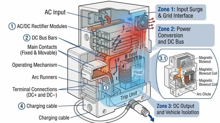
You MUST use DC-rated breakers for DC circuits. AC breakers rely on the natural zero-crossing of alternating current (120 times/second at 60Hz) to extinguish arcs. DC has no zero-crossing—arcs sustain indefinitely and can weld contacts together. DC breakers have larger contact gaps, magnetic blowout coils, and arc chutes to safely interrupt DC current. An AC breaker on DC will fail catastrophically during a fault condition, potentially causing arc flash, fire, or explosion. Always verify “DC” marking and voltage rating on the breaker label.
The 40 amp DC circuit breaker serves as a versatile mid-range protection device for solar charge controllers, RV distribution systems, and marine equipment. Proper sizing requires careful load analysis, NEC 125% rule application, and wire sizing verification.
Lista di controllo per la selezione:
– [ ] Calculate actual load current (including low-voltage scenarios)
– [ ] Apply 125% factor for continuous loads (>3 hours)
– [ ] Verify 40A adequate or upsize to 50A/60A
– [ ] Size wire minimum 8 AWG (upsize for voltage drop)
– [ ] Check ambient temperature derating (<40°C preferred) – [ ] Calculate voltage drop (<3% for branch circuits) – [ ] Select DC-rated breaker (never use AC breaker) – [ ] Choose voltage rating ≥ system maximum (32V for 12V, 80V for 48V) Wire Sizing Quick Guide:
- 12V systems: 6-4 AWG for runs >10 feet
- 24V systems: 8-6 AWG typical
- 48V systems: 8 AWG adequate for most installations <25 feet Installation Reminders:
– Mount in accessible location (within 3-second reach)
– Torque terminals properly (150-180 in-lbs for 8 AWG)
– Label circuit clearly with amperage and purpose
– Test before and after energization
– Thermal scan after 1 hour under load
When to Upsize to 50A or 60A:
– Load exceeds 32A continuous (40A ÷ 1.25)
– Ambient temperature >50°C (significant derating)
– Future equipment upgrades planned
– Load includes high inrush current (motors, inverters)
– Extra safety margin desired for critical circuits
The 40A rating provides an economical protection solution for many residential and mobile DC applications when properly sized and installed following NEC guidelines and manufacturer specifications.