Indirizzo
304 Nord Cardinale
St. Dorchester Center, MA 02124
Orario di lavoro
Da lunedì a venerdì: dalle 7.00 alle 19.00
Fine settimana: 10.00 - 17.00
Indirizzo
304 Nord Cardinale
St. Dorchester Center, MA 02124
Orario di lavoro
Da lunedì a venerdì: dalle 7.00 alle 19.00
Fine settimana: 10.00 - 17.00

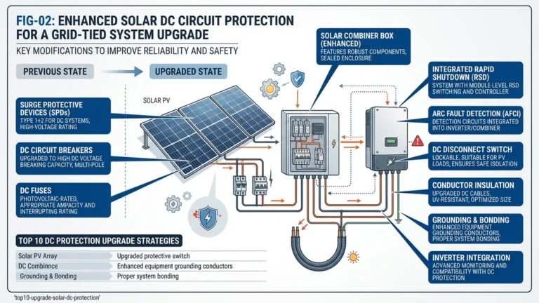
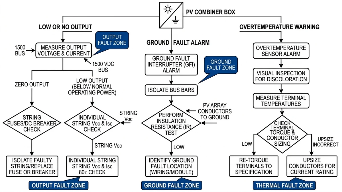
To diagnose a PV combiner box fault, map the symptom to its most likely fault zone first: output voltage drop points to string-level fuse or breaker failure, ground fault alarms indicate insulation breakdown, and overtemperature warnings typically trace back to loose terminals or an undersized conductor.
Before opening the enclosure, check the monitoring system for string current imbalance. A healthy string in a 1500 VDC system typically delivers within ±5% of its rated Isc. Any string reading below 80% of expected output warrants immediate investigation. In a 62 MW ground-mount installation in Hebei Province (2023), maintenance crews using this threshold caught three failed fusibili gPV during routine monitoring before any inverter-level alarm triggered.
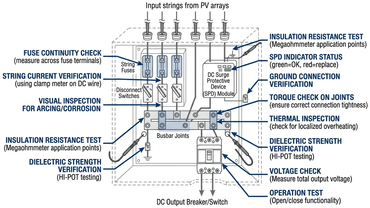
Once on-site, inspect the enclosure exterior for discoloration, deformation, or moisture ingress. Thermal imaging is the most efficient first tool — terminal hotspots above 40°C above ambient temperature indicate resistive faults from loose connections or corroded busbars.
Isolate the combiner box using the main Sezionatore DC before opening. With the box de-energized, test each string fuse for continuity. Per IEC 60269-6, gPV fuses rated for photovoltaic applications must withstand reverse current and sustained overload conditions — a blown fuse with no visible cause often points to a recurring overcurrent event rather than a one-time fault.
Check the surge protection device status indicator; a tripped SPD with no storm event logged suggests a sustained overvoltage condition on the DC bus. Cross-reference string open-circuit voltage against the module datasheet — values deviating more than 10% from calculated Voc indicate either cell degradation or a wiring fault upstream.
For wiring reference during reassembly or fault tracing, the Guida al cablaggio della scatola combinatore FV covers terminal sequencing and torque specifications that directly affect connection integrity.
When one string drops out while the rest of the combiner remains productive, start with the string protection path before assuming a module or inverter problem.
Reverse current occurs when a shaded or degraded string drops below the combined back-voltage of parallel strings in the combiner. Current flows backward through the weak string at magnitudes that can reach 2–3× the string’s rated short-circuit current (Isc). IEC 62548-1 specifies that string protection devices must interrupt this reverse current before sustained thermal damage occurs. A gPV fuse rated to IEC 60269-6 is designed for this duty; a standard gG fuse is not.
Thermal fatigue also accumulates over years of daily cycling. In a 35 MW ground-mount installation in Gansu Province (2023), maintenance crews found that roughly 60% of blown string fuses showed terminal discoloration consistent with long-term thermal cycling rather than a single overcurrent event.
Step 1 — Isolate the string. Open the main DC disconnect and confirm zero voltage at the combiner bus before touching internal components.
Step 2 — Identify the suspect string. Cross-reference monitoring data for strings showing zero or abnormally low current output.
Step 3 — Inspect the fuse or breaker visually. Look for discoloration, swollen fuse bodies, or tripped breaker indicators. A blown DC fuse will often show carbon tracking on the fuse holder.
Step 4 — Measure string open-circuit voltage (Voc). Verify the string Voc is within ±5% of the expected value before replacing the protective device. A reading below 80% of expected Voc suggests a module-level or wiring fault, not just a blown fuse.
Step 5 — Check for reverse current conditions. Measure current direction on adjacent strings. If neighboring strings are pushing current back through the weak string path, investigate shading, soiling, or module degradation before installing a new fuse.
Step 6 — Replace with the correct device. Match the replacement to the original specification: voltage rating aligned with system architecture, current rating per string design, and a gPV or equivalent DC-rated interrupting class. Refer to the PV combiner box wiring guide for fuse holder compatibility and termination torque.
Step 7 — Monitor post-replacement. Log string current for at least 48 hours. A repeat trip within one thermal cycle usually means the root cause remains.
[Expert Insight]
– If a replacement fuse opens again within the same sunny day, do not keep swapping parts; compare the suspect string current profile against neighboring strings hour by hour to catch intermittent shading or connector heating.
– On breaker-fed strings, manually operate the handle several times after isolation; a stiff or inconsistent mechanism often signals internal contact damage even if the breaker has not visibly tripped.
– Photograph fuse holders before removal so heat tinting and carbon marks are documented for later root-cause review.
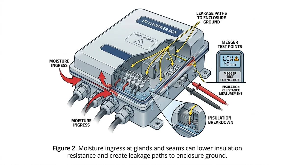
Ground-fault alarms that appear intermittently, especially after rain or morning condensation, usually point to insulation resistance loss rather than a hard short.
Water is the primary driver of insulation resistance failure in combiner boxes. When enclosure seals degrade after years of UV exposure and thermal cycling, condensation forms on busbars, terminal blocks, and fuse holders. In a 32 MW ground-mount installation in Anhui Province (2023), technicians traced a recurring ground fault alarm to a single combiner box where failed cable gland seals allowed seasonal humidity to drop IR values below 0.5 MΩ.
Contamination compounds the problem. Dust and salt deposits absorb moisture and form a conductive film across insulation surfaces, especially in coastal and desert installations.
Step 1 — Isolate the combiner box completely. Open the DC switch disconnector and verify zero voltage on all terminals with a calibrated meter.
Step 2 — Disconnect all string inputs and the DC output cable to avoid back-feeding the megger through the inverter or fuse network.
Step 3 — Apply 500 VDC test voltage for systems up to 1000 V, or 1000 VDC for 1500 V systems, between the combined positive/negative conductors and the enclosure earth. Maintain for 60 seconds.
Step 4 — Record the stabilized IR value.
Acceptance thresholds per IEC 62446-1:
Step 5 — If IR is marginal (0.5–1 MΩ), dry the enclosure with a heat gun, re-seal cable glands, and retest after 24 hours. If IR stays low after drying, the insulation material or connected component is already compromised and should be replaced.
Proper reassembly and routing practices help reduce insulation stress. The PV combiner box wiring guide is a useful reference.
If a combiner passes fuse checks but still shows vulnerability after storm activity or unexplained DC-side disturbances, the next component to evaluate is the SPD.
A surge protective device degrades a little with every surge event because its MOV depends on zinc oxide grain boundaries that change under heat stress. Each transient shifts the varistor voltage downward and increases leakage current. A 50 MW ground-mount installation in Yunnan Province (2023) found that SPDs in ridge-line combiner boxes showed leakage currents exceeding 1 mA DC at rated voltage after just 18 months.
Once leakage current at continuous operating voltage exceeds 1 mA, thermal runaway risk rises sharply.
Selecting the wrong Uc rating is a frequent installation error. Uc must be at least 1.1 × the maximum continuous operating voltage of the PV string circuit. Undersizing Uc causes premature thermal stress; oversizing reduces clamping effectiveness.
| Tensione del sistema | Minimum Uc Required | Recommended Up (Protection Level) | Typical MOV Diameter |
|---|---|---|---|
| 600 VDC | 660 VDC | ≤ 2.0 kV | 20 mm |
| 1000 VDC | 1100 VDC | ≤ 2.5 kV | 32 mm |
| 1500 VDC | 1650 VDC | ≤ 4.0 kV | 40 mm |
For replacement, always match or exceed the original Uc rating and verify the discharge current rating, typically 20 kA for Type 2 SPDs in string combiner applications. Sinobreaker’s surge protection device range covers all three voltage tiers with IEC 61643-11 certification.
Replacement acceptance criterion: measure leakage current Ileak at Uc using a DC insulation tester. Accept if Ileak < 0.5 mA. Reject and replace if Ileak ≥ 1 mA or if Vn has drifted > 10% from the nameplate value.
[Expert Insight]
– Replace SPD modules in matched sets on the same polarity path when one unit shows severe drift; mixed-age modules can leave uneven protection margins.
– After any nearby lightning event, check not only the SPD status window but also the grounding conductor termination, since a loose PE path can make a healthy SPD look ineffective.
– Keep a record of installation date and lightning season exposure by site zone; ridge rows, end rows, and isolated structures usually age faster than interior rows.
Heat damage inside a combiner box usually develops at connection points first, so thermal and visual evidence here often explains nuisance trips, output loss, or enclosure odor.
Infrared thermography is the primary diagnostic tool for this fault zone.
Step 1 — Establish baseline load. Perform the scan only when strings are producing at least 70% of rated current, since thermal differentials are unreliable at low irradiance.
Step 2 — Scan all busbar joints, terminal blocks, and cable lugs. Flag any point showing a temperature rise of 10°C or more above ambient as a warning condition; a rise of 25°C or more above ambient requires immediate isolation and inspection.
Step 3 — Document hotspot coordinates against the combiner layout. Cross-reference with the string current log to confirm the hotspot aligns with a loaded conductor rather than a background heat source.
Step 4 — Re-scan after corrective action to confirm the anomaly has cleared.
In a 22 MW rooftop installation across eight logistics warehouses in Zhejiang Province (2023), quarterly IR scans identified 14 terminal hotspots averaging 38°C above ambient, all traced to under-torqued lugs installed during commissioning.
Torque values vary by conductor cross-section and terminal type. Typical field reference values:
Always use a calibrated torque wrench. Re-torque all terminals at the 12-month service interval because thermal cycling causes creep relaxation in copper and aluminum conductors.
Arc tracking leaves carbonized trails across insulation surfaces that permanently reduce surface resistivity. If carbon tracking is visible on any busbar insulator, terminal block housing, or enclosure wall, replace the affected component before returning the combiner box to service. For replacement component selection, refer to the Fusibile CC e Interruttore CC resources, then verify reinstallation against the PV combiner box wiring guide.
Once the immediate fault is cleared, a fixed maintenance cadence helps prevent the same failure mode from returning later.
Visual inspection only. Confirm no physical damage to the enclosure, no moisture ingress, and no visible discoloration on terminals or busbars. Check that the enclosure IP rating has not been compromised by cracked seals or missing cable glands.
Measure and log open-circuit voltage for each string. A deviation greater than 5% from expected value warrants further investigation. Inspect gPV fuses for signs of thermal stress. Verify that the surge protection device status indicator shows green.
Perform infrared thermography on all terminals and busbars under load. Torque-verify all connections to manufacturer specifications. Test each DC circuit breaker for correct trip response. Replace any fuse showing resistance drift above 10% from baseline reading. Review wiring condition against the original installation documentation.
Immediately after lightning or severe weather, inspect SPD cartridges for depletion, check enclosure seals for water intrusion, and re-verify string Voc values. In a 35 MW ground-mount installation in Shandong Province (2023), post-typhoon inspections identified SPD failures in 18% of combiner boxes before the next energization.
Replace all gPV fuses regardless of apparent condition, as electrochemical aging degrades current-limiting performance without clear visual indicators. Recalibrate or replace monitoring sensors, assess busbar plating for oxidation, and consider upgrading protection components if system voltage has changed since commissioning.
| Intervallo | Key Tasks |
|---|---|
| Monthly | Visual inspection, enclosure integrity |
| Quarterly | String Voc measurement, SPD status, fuse visual check |
| Annuale | IR thermography, torque check, breaker trip test |
| Post-storm | SPD replacement, seal inspection, Voc re-verification |
| 5-Year | Full component replacement, sensor recalibration |
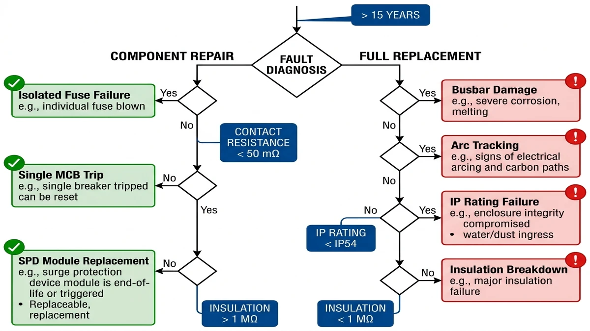
After diagnosis, the maintenance decision comes down to whether the box can be restored safely with parts or whether the enclosure itself has aged past economical repair.
Repair is viable when damage is isolated, the enclosure and busbar assembly are structurally sound, and the root cause is a single identifiable component. Typical repair candidates include:
In a 22 MW ground-mount installation in Hebei Province (2023), maintenance crews replaced individual fuses and SPD modules across 18 combiner boxes without a full enclosure swap, restoring full output within one working day.
Replace the entire unit when damage compromises enclosure integrity or the busbar system. Non-negotiable replacement triggers include:
For component interaction under fault conditions, the PV combiner box complete guide explains the major assemblies.
If recurring failures trace back to undersized or aging protection hardware, upgrading the protection scheme can reduce repeated part replacement.
Correctly specified string protection should reflect the system’s actual operating voltage, continuous current, and surge exposure. IEC 62548-1 requires string overcurrent protection devices to carry continuous current at no less than 1.25 × Isc per string, and in 1500 VDC systems that often places string protection in the 15 A to 20 A range depending on module configuration.
Sinobreaker’s gPV fuse series and DC MCB range are rated for 1000–1500 VDC photovoltaic applications, covering the voltage classes and breaking capacities most often flagged during troubleshooting. Pairing string-level fusing with a surge protection device rated to IEC 61643-31 adds a second layer of defense against transient overvoltages that fuses alone cannot absorb. In a 35 MW ground-mount installation in Hebei Province (2024), upgrading combiner boxes with correctly rated string fuses and SPDs reduced nuisance tripping by roughly 70% over the following six months.
For connection sequencing and protection coordination before specifying replacements, see the PV combiner box wiring guide.
The earliest sign is often string imbalance in the monitoring platform, such as one string producing far less current than adjacent strings under the same irradiance.
A failed fuse usually appears on monitoring as zero or sharply reduced string current, then should be confirmed by safe isolation and a continuity check.
Values below the maintenance threshold require investigation, and very low readings mean the affected circuit should be taken offline until the source of leakage is corrected.
They should be checked during routine maintenance and after lightning or severe weather, since degradation can occur even when the device has not visibly failed.
No. Carbonized tracking permanently weakens the insulation surface, so the affected part should be replaced rather than cleaned and reinstalled.
Full replacement is the safer option when enclosure sealing is compromised, busbars are heat-damaged, insulation has broadly deteriorated, or spare parts are no longer available.
Normal current can still create excessive heat if a lug is loose, oxidized, or improperly torqued, because resistance rises at the connection point.
For lightning and surge protection principles in PV systems, see https://www.iec.ch/.