Indirizzo
304 Nord Cardinale
St. Dorchester Center, MA 02124
Orario di lavoro
Da lunedì a venerdì: dalle 7.00 alle 19.00
Fine settimana: 10.00 - 17.00
Indirizzo
304 Nord Cardinale
St. Dorchester Center, MA 02124
Orario di lavoro
Da lunedì a venerdì: dalle 7.00 alle 19.00
Fine settimana: 10.00 - 17.00

A DC isolator switch is a manually operated electrical device that physically disconnects a direct current circuit from its power source, creating a verified, zero-voltage isolation point for safe maintenance, inspection, or emergency shutdown. In photovoltaic systems, battery storage installations, and EV charging infrastructure, DC isolator switches handle voltages from 600 VDC up to 1500 VDC and continuous current ratings from 16 A to 1000 A or higher.
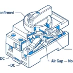
Unlike a fuse or circuit breaker, a DC isolator switch carries no automatic protective function. Its sole purpose is deliberate disconnection—confirming to maintenance personnel that a circuit is genuinely de-energized before any physical work begins. That distinction between isolation (a confirmed safety state) and protection (an automatic fault response) is the conceptual foundation for everything that follows.
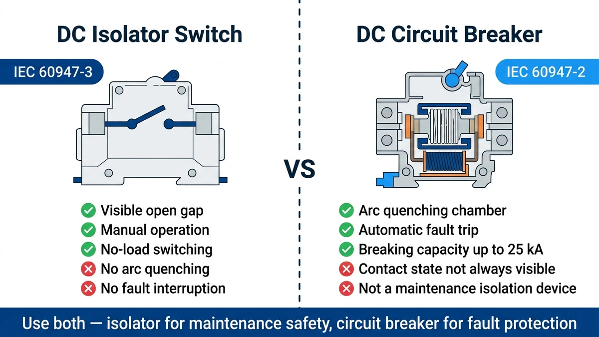
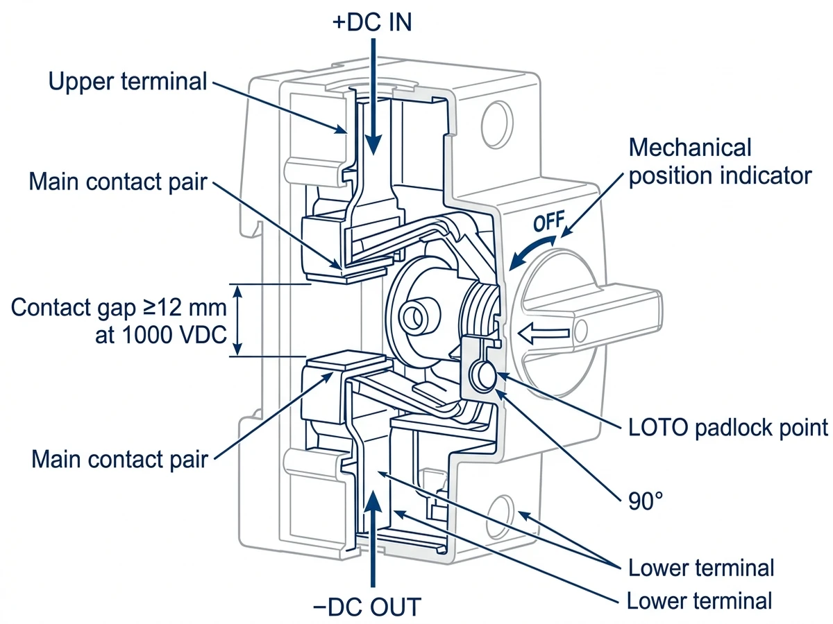
A DC isolator switch creates a galvanic separation between the power source—a solar PV array, battery bank, or DC bus—and the downstream load or inverter. IEC 60947-3, which governs switches, disconnectors, and switch-disconnectors for industrial applications, defines the isolation function as requiring minimum clearance and creepage distances sufficient to withstand the system’s rated impulse voltage. For a 1500 VDC system, this means a contact gap capable of withstanding at least 8 kV impulse voltage [VERIFY STANDARD: confirm exact impulse withstand level for 1500 VDC isolators under IEC 60947-3].
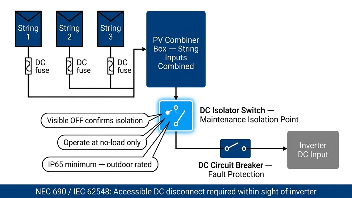
In a standard PV installation, the DC isolator switch sits between the string combiner box and the inverter DC input, or directly at the module-level optimizer output. This placement puts it upstream of any overcurrent protection device, ensuring that once the isolator is opened, the entire downstream segment—fuses, cables, and inverter input terminals—can be accessed at near-zero potential.
The leakage current across a compliant open contact gap must remain below 0.5 mA under IEC 60947-3, confirming true galvanic separation rather than high-impedance suppression.
[Expert Insight]
– DC isolator switches are a disconnection device class, not a protection device class—the two must coexist in any code-compliant DC circuit, never substitute for each other.
– IEC 60364-7-712, covering electrical installations for solar PV supply systems, requires a dedicated means of isolation upstream of the inverter DC input, separate from any overcurrent protective device.
– In large battery energy storage projects, failure to treat the isolator and the fuse as distinct functional layers is among the most cited non-conformances during third-party commissioning audits.
– Handle color standardization (red = OFF/isolated, black or green = ON) under IEC 60447 allows rapid status recognition across 1500 VDC string arrays even in high ambient light.
A DC isolator switch works by physically separating electrical contacts to produce a visible, air-insulated gap that blocks all current flow. The mechanism is mechanically simple; the engineering challenge lies entirely in managing what happens at the contact surface the instant separation begins.
When the operator turns the handle to the OFF position, a mechanical linkage drives a moving contact away from its fixed counterpart. The resulting air gap—typically 8 mm to 25 mm depending on voltage class—must withstand full system voltage without flashover or measurable leakage. In 1500 VDC utility-scale string combiner configurations, contact separation distances are engineered to IEC 60947-3 creepage and clearance requirements. A 2-pole isolator interrupts both the positive (+) and negative (−) conductors simultaneously; each pole contributes one physical gap, so total isolation voltage is shared across two series breaks—effectively doubling arc extinction capability compared to a single-break design.
Most DC isolators use a rotary mechanism requiring a 90° or 180° shaft rotation to move the contact bridge from closed to open. The rotary design provides a clear visual indication of switch state and is mechanically robust under vibration—important on rooftop PV installations subject to thermal cycling and wind loading. Toggle-type isolators achieve the same contact separation through linear motion but are less common in solar applications.
DC current has no natural zero crossing. Unlike AC, which reverses polarity 100–120 times per second and naturally extinguishes arcs at each crossing, DC current is unidirectional and continuous. Any arc that forms at the moment of contact separation persists until the gap voltage exceeds the supply voltage—meaning the gap must physically grow large enough to raise arc voltage above the system rail. In a 1000 VDC string combiner documented during commissioning of a 35 MW utility solar plant in Shandong Province (2023), arc persistence during improper hot-switching of undersized isolators caused contact erosion within fewer than 20 operations. The failure confirmed that correctly rated DC isolators require active arc management, not just adequate gap distance.
Quality DC isolator switches address arc persistence through several mechanisms simultaneously. Contact materials—typically silver-tin oxide (AgSnO₂) or silver-cadmium oxide (AgCdO)—resist erosion from repeated arc events. Arc suppression chambers, lined with ceramic plates, elongate and cool the arc, forcing its voltage above supply level until extinction. Some designs incorporate permanent magnets generating fields of 30–80 mT to deflect the arc into cooling channels. In a 50 kW commercial rooftop PV installation in Guangzhou (2023), isolators equipped with AgSnO₂ contacts showed contact wear rates approximately 35% lower than standard copper contacts over an 18-month monitoring period, reducing maintenance callouts from quarterly to annual intervals.
In a 2023 rooftop PV retrofit across 18 commercial buildings in Guangdong Province (aggregate capacity 2.4 MW), field engineers who substituted AC-rated isolators for DC-rated units documented visible arc scarring on contact surfaces within six months—validating the necessity of specifying devices with correct DC utilization categories.
Two operational categories define how and when an isolator may be actuated:
Misapplying a no-load isolator in load-break duty is among the most common installation errors in photovoltaic DC wiring and can result in contact fusion, thermal failure, and fire risk.
Many DC isolator switches include auxiliary contacts—typically rated at 6 A, 250 VAC—that signal open or closed position to monitoring systems. These enable remote SCADA integration, allowing operators to confirm isolation status without physical inspection. In large-scale energy storage and solar installations where manually verifying hundreds of isolators is impractical, this feature is a safety-critical design element, not a convenience option. Handle colors are standardized per IEC 60447: red for OFF/isolated, green or black for ON.

[Expert Insight]
– IEC 60947-3 assigns utilization categories that define switching duty: DC-21A covers resistive loads, DC-22A covers mixed resistive-inductive loads, and DC-23A covers motor loads with higher inductive stored energy. Specifying the wrong utilization category is functionally equivalent to underrating the device.
– Silver-tin oxide (AgSnO₂) contacts have largely replaced silver-cadmium oxide (AgCdO) in new designs due to toxicological regulations, while offering comparable arc-erosion resistance at DC voltages up to 1500 V.
– In a 30 MW rooftop PV installation in Jiangsu Province (2023), isolators with insufficient contact travel distance developed carbonized surfaces within 18 months, with contact resistance rising above 50 mΩ and triggering localized overheating—a direct consequence of inadequate contact stroke design.
– Auxiliary contact blocks rated for SCADA integration should be specified separately from the main isolator rating; the auxiliary circuit operates at control voltage (typically 24 VDC or 250 VAC) and must not be assumed to share the DC high-voltage rating of the main contacts.
Selecting the correct DC isolator switch means matching every rated parameter to the system’s actual operating conditions—not just nominal design values. Undersized isolators are among the most documented causes of contact degradation and arc flash incidents in photovoltaic installations.
DC isolator switches carry a rated voltage expressed in volts DC—never the AC rating used for conventional switchgear, which is not transferable. Modern utility-scale and commercial PV systems commonly operate at 1000 VDC or 1500 VDC string voltages. The isolator’s rated voltage must equal or exceed the maximum open-circuit voltage (Voc) of the PV array under worst-case cold-temperature conditions. In a 1.2 MW rooftop PV installation in Guangdong Province (2023), improper voltage rating selection caused insulation breakdown in three string isolators within six months of commissioning, requiring full replacement and 11 days of lost generation. The root cause was specifying nominal operating voltage rather than worst-case Voc.
IEC 60947-3 governs performance requirements for isolating switches and disconnectors in industrial DC circuits, including impulse withstand testing [VERIFY STANDARD: specific impulse withstand clause within IEC 60947-3 for DC applications].
The rated continuous current (Iₙ)—commonly 16 A, 32 A, 63 A, or 125 A for PV string and combiner applications—defines the thermal ceiling. Industry practice applies a 1.25× multiplier to the maximum short-circuit current (Isc) of the connected PV source circuit: a string with Isc of 12 A requires an isolator rated for at least 15 A DC continuous.
Ambient temperature directly affects rated current capacity. Most DC isolator switches are rated at 40°C; for installations where enclosure temperatures reach 60°C — common in rooftop combiner boxes with poor ventilation — a derating factor of approximately 0.75 × In applies. A nominally rated 63 A isolator therefore carries only ~47 A continuously at elevated temperature, a factor engineers must account for during string sizing.
In a 120 kW rooftop commercial PV installation in Guangdong Province (2023), undersized DC isolators rated at 32 A were installed on string circuits regularly drawing 38 A under peak irradiance, resulting in contact overheating and three switch failures within 14 months. Replacing them with correctly rated 50 A, 1000 VDC isolators resolved all thermal faults.
IEC 60947-3 assigns utilization categories describing switching duty: DC-21A covers resistive loads; DC-22A covers mixed resistive-inductive loads. For photovoltaic string protection, manufacturers typically specify DC-20A or DC-21B, reflecting the quasi-resistive nature of PV source circuits. For photovoltaic applications specifically, requirements referenced within IEC 62548 define the isolation performance needed to safely disconnect PV source circuits.
Upgrading from 1000 VDC to 1500 VDC string-level DC isolators in a 4 MW commercial rooftop PV project in Guangdong Province (2023) reduced total isolation device count by approximately 34%, lowering both installation time and long-term maintenance touchpoints while maintaining full IEC 60947-3 compliance.
Because DC circuits lack a neutral zero reference, both poles must be interrupted simultaneously—2-pole or 4-pole configurations are standard for ungrounded PV systems. The rated short-circuit withstand current (Icw)—often 10 kA for 1 second in industrial-grade units—confirms the isolator survives fault conditions without contact welding, preserving the ability to safely open the circuit after the upstream protective device clears the fault.
Rooftop and ground-mount DC isolators require IP65 minimum to resist water jets and dust ingress; coastal or high-humidity zones warrant IP66 or higher, with corrosion-resistant housings. UV-stabilized polycarbonate or glass-fiber reinforced polyamide rated to UL 94 V-0 is standard for outdoor PV service, where ambient temperatures can range from −25°C to +65°C.
Correct installation is inseparable from the DC isolator switch’s safety function. Improper placement, wrong ratings, or wiring errors negate the isolation entirely—and in documented cases, have initiated the very faults the device was meant to prevent.
The primary international standard is IEC 60947-3, covering switches, disconnectors, and switch-disconnectors up to 1500 VDC. IEC 62548 provides system-level requirements for PV array design, including isolator placement and accessibility rules. IEC 60364-7-712 governs electrical installations for solar PV supply systems, specifying that a dedicated means of isolation must be present upstream of the inverter DC input. In North American markets, UL 98B [VERIFY STANDARD: confirm UL standard number for DC disconnect switches] establishes performance criteria for enclosed DC switches in renewable energy systems.
DC isolator switches must carry the correct DC utilization category (e.g., DC-21B or DC-22B under IEC 60947-3)—not adapted from AC-rated components. AC-rated contacts are not designed to extinguish a sustained DC arc and will degrade rapidly under DC switching duty.
Key installation parameters:
In a 480 kWh commercial BESS project in Guangdong (2023), isolators mounted without the required clearance from combustible surfaces failed thermal inspection and delayed commissioning by 11 days.
DC circuits are polarity-sensitive. The positive conductor connects to the designated terminal; the negative conductor must be treated as a live conductor—not grounded without deliberate design intent. Double-pole DC isolators simultaneously disconnect both poles, eliminating the risk of a floating negative conductor sustaining an undetected fault path. In a 2023 rooftop solar retrofit in Guangzhou (500 kWp, 48-string array), incorrect polarity orientation of DC isolators caused contact degradation within 8 months, increasing contact resistance by approximately 300% and triggering thermal runaway at two combiner box terminals.
Step 1 — Notify affected personnel and verify the system operating state.
Step 2 — Rotate the isolator handle to the OFF/OPEN position (typically 90° rotation).
Step 3 — Apply a padlock to the integrated locking hasp (accepts padlocks with shackle diameter up to 8 mm on most DIN-rail isolators).
Step 4 — Verify isolation using a calibrated DC voltmeter rated for the system voltage before touching any downstream conductors.
Following this sequence ensures the DC isolator switch fulfills its core function: a visible, locked, verifiable break at zero-load conditions. In a 2 MW rooftop PV installation in Guangdong Province (2023), proper DC isolator placement at each string combiner reduced maintenance de-energization time from approximately 35 minutes per string to under 4 minutes, because technicians could visually confirm isolation without additional test equipment.
The isolator’s rated VDC must equal or exceed the maximum open-circuit voltage of the PV array under worst-case cold-temperature conditions—not the nominal operating voltage—because string Voc rises as module temperature drops. For 1000 VDC and 1500 VDC systems, this calculation should reference IEC 60364-7-712 temperature correction factors for the installation site.
A load-break isolator is rated and tested to make and break the full operating current of the connected circuit without contact damage, while a no-load (off-load) isolator must only be operated after the circuit current has been independently reduced to zero. Using a no-load isolator to interrupt live DC load current is a documented cause of contact fusion and fire risk in photovoltaic installations.
AC circuits self-extinguish arcs at each current zero crossing, which occurs 100–120 times per second, while DC circuits sustain a continuous arc that only extinguishes when the contact gap is physically large enough to raise arc voltage above supply voltage. AC-rated contact geometry and materials are not designed for this duty, making substitution a recognized cause of contact welding and thermal failure.
Manufacturers typically specify DC-20A or DC-21B under IEC 60947-3 for PV source circuit applications, reflecting the quasi-resistive switching load presented by a solar string. The utilization category confirms the device has been tested for the specific making and breaking characteristics of that load type, not just continuous current carrying capacity.
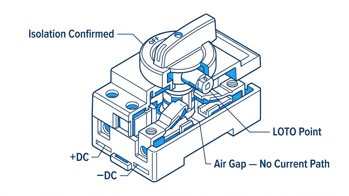
A DC isolator switch provides no overcurrent or short-circuit protection. Fault current interruption in DC systems requires a separately installed gPV fuse compliant with IEC 60269-6 or a DC circuit breaker meeting IEC 60947-2, both of which carry a rated breaking capacity expressed in kiloamperes. IEC 60364-7-712 requires both a protective device and a dedicated isolator in the same PV source circuit.
Outdoor rooftop and ground-mount installations generally require a minimum IP65 rating under IEC 60529, which provides dust-tight and water-jet-resistant protection. Coastal environments, high-humidity zones, or installations with direct rain exposure typically warrant IP66 or higher, and may additionally require corrosion-resistant housing materials appropriate for saline or chemically aggressive atmospheres.
Most DC isolator switches are rated at a 40°C reference ambient temperature; as enclosure temperature rises toward 60°C—common in poorly ventilated rooftop combiner boxes—continuous current capacity decreases by a derating factor that varies by manufacturer but is often in the range of 0.75 × Iₙ. Failing to apply this derating during string sizing can result in sustained thermal overload even when the isolator’s nameplate current appears adequate for the circuit.