Indirizzo
304 Nord Cardinale
St. Dorchester Center, MA 02124
Orario di lavoro
Da lunedì a venerdì: dalle 7.00 alle 19.00
Fine settimana: 10.00 - 17.00
Indirizzo
304 Nord Cardinale
St. Dorchester Center, MA 02124
Orario di lavoro
Da lunedì a venerdì: dalle 7.00 alle 19.00
Fine settimana: 10.00 - 17.00


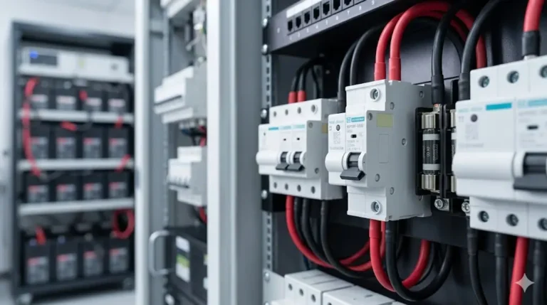
A solar fuse panel (also called a PV combiner box) consolidates multiple solar array strings into a single output while providing individual overcurrent protection for each string. This critical component prevents reverse current damage, enables string-level isolation, and ensures NEC-compliant installation for residential and commercial photovoltaic systems.
This comprehensive installation guide covers fuse panel selection, NEC 690 sizing requirements, busbar layout design, wire termination methods, grounding procedures, and professional mounting techniques for reliable long-term solar system performance.
Individual residential solar panels cannot be directly paralleled without protection:
Reverse Current Hazard:
Normal Operation (all panels producing):
String 1: 10A → Combiner → 40A total output
String 2: 10A ↗
String 3: 10A ↗
String 4: 10A ↗
Fault Condition (String 1 shaded/damaged): String 1: 0A ← 30A REVERSE CURRENT from other strings! String 2: 10A → Combiner → 30A output String 3: 10A ↗ String 4: 10A ↗
Result without fuse: String 1 panels overheat and fail Result with fuse: String 1 fuse opens, isolates fault
NEC Requirements for Fuse Panels:
– NEC 690.9(A): Overcurrent protection required if 3+ strings paralleled
– NEC 690.16: Current-limiting overcurrent devices for certain systems
– NEC 690.31(C): Accessible disconnecting means
– NEC 110.26: Working space clearances
– NEC 312: Enclosure requirements
Applicazioni comuni:
– Residential rooftop solar (4-12 string combiner)
– Commercial solar arrays (12-24 string combiner)
– Ground-mount solar farms (large multi-string combiners)
– Off-grid battery charging systems
– Grid-tie inverter input protection
Step 1: Determine String Short-Circuit Current (Isc)
Example Solar String:
8× 400W panels in series
Per panel Isc: 10.5A
String Isc: 10.5A (series = same current)
Step 2: Apply 156% Safety Factor (NEC 690.8(B)(1))
Required fuse rating ≥ String Isc × 1.56Calculation: 10.5A × 1.56 = 16.38A minimum
Select next standard fuse size: 20A gPV fuse
Why 156% Factor:
– 125% for continuous current (>3 hours)
– 125% for high irradiance conditions
– Combined: 1.25 × 1.25 = 1.56 (156%)
Step 3: Verify Wire Protection
String wire: 10 AWG (ampacity 40A at 75°C per NEC Table 310.16)
Fuse selected: 20A
Verification: 20A < 40A ampacity ✓ PASS
If fuse were 50A: 50A > 40A wire capacity ✗ FAIL (fire hazard!) Solution: Upsize wire to 8 AWG (50A ampacity)
Total Output Current Calculation:
System: 4 strings, 10.5A Isc each
Total output: 4 × 10.5A = 42A maximum
Output fuse sizing: 42A × 1.25 (continuous) = 52.5A minimum Select: 60A gPV fuse
Output wire sizing: 60A fuse requires minimum 6 AWG (65A ampacity) Voltage drop check: Calculate for actual run length
Series String Voltage Consideration:
String voltage: 8× 400W panels
Voc per panel: 49.2V
String Voc: 49.2V × 8 = 393.6V
Temperature correction (NEC 690.7): Cold temperature: -10°C (common winter low) Correction factor: 1.12 (from manufacturer datasheet) Maximum voltage: 393.6V × 1.12 = 440.8V
Required fuse voltage rating: ≥500V DC minimum Select: 600V DC rated gPV fuses (standard rating)

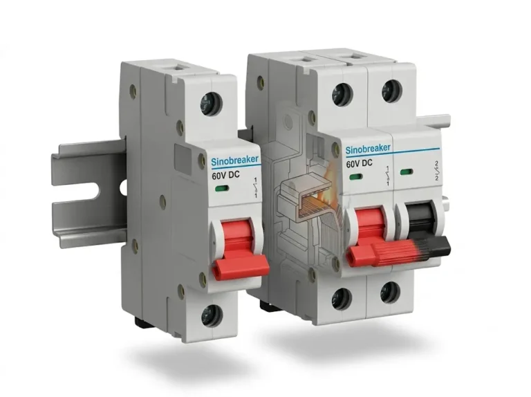
What “gPV” Rating Means:
g = Potere di interruzione a tutto campo (tedesco: ganzbereichsschutz)
PV = Applicazione fotovoltaica
gPV certification indicates: – Tested for DC photovoltaic reverse current interruption – Rated for high ambient temperature (70-90°C typical) – UV-resistant materials for outdoor mounting – Complies with IEC 60269-6 or UL 2579 standards – Approved for ungrounded PV systems
Why Standard DC Fuses Are Inadequate:
Standard DC Fuse (Not gPV):
- Rated for uni-directional current only
- Designed for forward current interruption
- Not tested for reverse current from paralleled sources
- Lower ambient temperature rating (40°C typical)
Solar Array Unique Conditions: – Reverse current from other strings (backfeed) – High ambient temperature (rooftop 70°C+ common) – Outdoor UV exposure for 25+ years – Ungrounded system voltage stress
Result: Standard DC fuse may fail catastrophically – Cannot interrupt reverse current safely – Overheats at high ambient temperature – UV degradation causes premature failure
gPV Fuse Specifications:
| Valutazione | Tensione | Interrupt Capacity | Ambient Temp | Costo |
|---|---|---|---|---|
| 10A gPV | 600 V CC | 20kA typical | 90°C | $8-12 |
| 15A gPV | 600 V CC | 20kA typical | 90°C | $8-12 |
| 20A gPV | 600 V CC | 20kA typical | 90°C | $10-15 |
| 30A gPV | 600 V CC | 20kA typical | 90°C | $12-18 |
Copper vs. Aluminum Busbars:
Copper (Preferred):
Advantages:
- Lower resistance (1.68 × 10⁻⁸ Ω·m)
- Better conductivity
- Easier to solder/terminate
- Corrosion-resistant with proper coating
Disadvantages: – Higher cost ($20-40 per busbar) – Heavier weight
Typical sizing for 4-string combiner: – 1/4″ thick × 2″ wide × 12″ long – Ampacity: 150-200A continuous
Aluminum (Budget Option):
Advantages:
- Lower cost ($10-20 per busbar)
- Lighter weight (1/3 of copper)
Disadvantages: – Higher resistance (2.82 × 10⁻⁸ Ω·m) – Requires larger cross-section for same ampacity – Oxidation requires anti-oxidant compound – Special crimping required (not solder-compatible)
Typical sizing for 4-string combiner: – 1/4″ thick × 3″ wide × 12″ long (larger than copper) – Ampacity: 150-200A continuous
Busbar Resistance Calculation:
Formula: R = ρ × L / AWhere: R = resistance (Ω) ρ = resistivity (Ω·m) L = length (m) A = cross-sectional area (m²)
Example: Copper busbar 12″ long, 1/4″ × 2″ L = 0.3048 m (12 inches) A = 0.00635 m × 0.0508 m = 0.000323 m² ρ = 1.68 × 10⁻⁸ Ω·m
R = (1.68 × 10⁻⁸ × 0.3048) / 0.000323 R = 0.0000159 Ω (15.9 microohms)
At 40A total current: Voltage drop = 40A × 0.0000159Ω = 0.00064V (negligible) Power loss = 40² × 0.0000159Ω = 0.025W (minimal heat)
NEMA Rating Requirements:
Rooftop Installation:
- Minimum: NEMA 3R (rainproof)
- Better: NEMA 4 (waterproof, hose-directed water)
- Best: NEMA 4X (waterproof + corrosion-resistant)
Ground-Mount Installation: – Minimum: NEMA 4 (splash/spray protection) – Better: NEMA 4X stainless steel (long-term durability)
Coastal/Marine Environments: – Required: NEMA 4X with 316 stainless steel – Reason: Salt spray causes rapid corrosion of standard enclosures
Material Selection:
Powder-Coated Steel (NEMA 3R):
- Cost: $80-150 for 12×16" combiner box
- Lifespan: 10-15 years
- Best for: Dry climates, protected mounting locations
Aluminum (NEMA 4): – Cost: $150-250 – Lifespan: 15-20 years – Best for: General outdoor use, moderate climates
304 Stainless Steel (NEMA 4X): – Cost: $300-500 – Lifespan: 20-30 years – Best for: Harsh environments, coastal areas (not direct saltwater)
316 Stainless Steel (NEMA 4X): – Cost: $500-800 – Lifespan: 30-40 years – Best for: Direct saltwater exposure, tropical marine environments
Thermal Management:
Solar fuse panels generate heat from:
1. Fuse internal resistance (I²R losses)
2. Busbar resistance
3. Connection resistance
4. Solar heating (black roof, 70°C ambient)
Ventilation Requirements:
- Passive vents: Top and bottom (25 sq in each minimum)
- Vent design: Labyrinth-style (prevents rain entry)
- Screen mesh: Insect/rodent protection
- Positioning: Fuse panel vertical (not horizontal) for convection
Active cooling (if needed): – 12V DC fan (10-15 CFM) – Thermostat-controlled (activates at 50°C) – Solar-powered option for off-grid installations
NEC 690.31(C) – Accessible Location Requirements:
Combiner/fuse panel must be:
- Readily accessible (no ladder required for operation)
- Near array but not in direct shadow path
- Within sight of array (visual confirmation of isolation)
- Protected from mechanical damage
- Minimum 3 feet from any opening (windows, vents)
Optimal Mounting Locations:
Rooftop Installations:
Preferred:
- North side of roof peak (shaded, cooler)
- Under eave overhang (rain protection)
- Near main service panel (shorter wire runs)
Avoid: – Direct south-facing (excessive heat) – Low roof areas (flooding, debris accumulation) – Under trees (falling branches, debris)
Ground-Mount Installations:
Preferred:
- Elevated pedestal (18-24" above grade)
- Concrete pad foundation (prevents settling)
- Near array edge (shorter string wiring)
Avoid: – Low-lying areas (flooding risk) – Direct soil contact (moisture, corrosion) – Under array panels (difficult access)
Hardware di montaggio:
Rooftop Mounting (on structural surface):
- Use 1/4" × 3" lag bolts
- Pre-drill pilot holes (3/16" for 1/4" bolt)
- Penetrate through roof membrane using proper flashing
- Seal all penetrations with butyl tape + sealant
- Use backing plate if mounting to single rafter
Ground Pedestal Mounting: – Pour 12″ × 12″ × 12″ concrete footing – Embed 1/2″ J-bolts in wet concrete (4 bolts) – Allow 7 days curing before loading – Use stainless steel hardware (corrosion resistance)
Proper Lug Selection:
Wire Size: 10 AWG (typical for 10-15A strings)
Required Lug: Copper compression lug, ring terminal
Sizing: 10 AWG wire → Yellow compression lug
Bolt hole: 1/4" or 5/16" (match busbar stud)
Incorrect lugs to avoid: – Crimp-on spade terminals (vibration-prone) – Solder terminals (heat failure in sun) – Barrel lugs (poor contact area)
Crimping Procedure:
Step 1: Strip wire insulation
- Length: 3/8" to 1/2" (match lug barrel length)
- Use wire stripper (not knife - prevents nicking)
- Inspect strands for damage
Step 2: Insert wire into lug – Strands fully inserted (no exposed copper outside barrel) – Wire insulation butts against lug shoulder
Step 3: Crimp lug – Use hydraulic compression crimper (not pliers!) – Crimp in center of barrel (not ends) – Apply full pressure (ratcheting crimper ensures complete crimp)
Step 4: Tug test – Pull wire with 30-40 lbs force – Wire should not pull out of lug – If fails: Discard and re-crimp with new lug
Step 5: Heat shrink – Slide heat shrink over crimped lug – Heat with heat gun (not lighter – uneven heating) – Shrink fully to create weather seal
Busbar Connection:
Torque Specifications:
- 1/4" busbar stud: 80-100 in-lbs
- 5/16" busbar stud: 120-150 in-lbs
- 3/8" busbar stud: 180-220 in-lbs
Connection sequence: 1. Place lug on busbar stud 2. Install split-lock washer (prevents loosening) 3. Install flat washer (distributes load) 4. Thread nut onto stud 5. Torque in stages: 50% → 75% → 100% 6. Verify no movement after torquing 7. Mark with torque seal paint (visual inspection indicator)
Polarity Management:
Critical: Positive and negative must not be reversed!
Labeling System:
- RED heat shrink: Positive (+) conductors
- BLACK heat shrink: Negative (-) conductors
- Wire labels: "String 1+", "String 1-", etc.
- Busbar labels: "POSITIVE BUS", "NEGATIVE BUS"
Physical separation: – Minimum 1.5″ spacing between positive and negative busbars – Use insulating barrier if closer spacing required – Color-code busbars: Red positive, Black negative
Verification before energizing: – Use multimeter to verify polarity at each connection – Measure string Voc with meter (verify expected voltage) – Check polarity at output terminals before connecting inverter
Equipment Grounding (NEC 690.43):
All metal enclosures and frames must be grounded:
Grounding Electrode Conductor Sizing (NEC Table 250.122):System Maximum Overcurrent Device → Minimum Ground Wire 15A fuses → 14 AWG 20A fuses → 12 AWG 30A fuses → 10 AWG 60A fuses → 10 AWG 100A fuses → 8 AWG 200A fuses → 6 AWG
Procedura di installazione:
Step 1: Ground busbar installation
- Mount copper ground busbar inside enclosure
- Use 6 AWG minimum conductor
- Minimum 4 connection points for string grounds
Step 2: Enclosure bonding – Green bonding screw threads into enclosure back – Connects ground busbar to enclosure metal – Ensures enclosure at ground potential
Step 3: Array frame grounding – Run grounding electrode conductor from ground busbar to array frame – Use listed grounding clamps (not self-tapping screws) – Bond each solar panel frame to grounding system
Step 4: System grounding electrode – Connect to existing building ground (preferred) – Or install dedicated ground rod (8 ft × 5/8″ copper-clad minimum) – Drive rod to full depth (only 1-2″ exposed) – Use approved ground rod clamp
Step 5: Grounding verification – Measure resistance from enclosure to ground: Should be <1Ω – Measure resistance from array frame to ground: Should be <1Ω – If >1Ω: Check connections, clean bonding surfaces, verify ground rod integrity
Ground Fault Protection:
For ungrounded PV systems (most residential):
- Ground fault protection device (GFPD) required per NEC 690.41(B)
- Typically integrated in inverter
- Fuse panel grounding ensures chassis protection only
- GFPD detects current leakage to ground (30-300mA threshold)

Lista di controllo per l'ispezione visiva:
Enclosure:
☐ Securely mounted (no movement when pushed)
☐ Gaskets intact (no gaps in seal)
☐ Drainage holes at bottom (outdoor installations)
☐ No visible damage or corrosion
☐ Door opens/closes smoothly with proper latch
Internal Components: ☐ All fuses proper rating and type (gPV-rated) ☐ Fuses seated fully in holders ☐ Busbars straight, no bends or cracks ☐ All connections tight (visual verification of torque seals) ☐ No exposed conductors (heat shrink intact) ☐ Labels present and legible on all circuits
Wiring: ☐ Correct wire gauge for ampacity ☐ Proper polarity (red/black color coding) ☐ No damaged insulation ☐ Wire support every 18″ (prevents sagging) ☐ Proper bend radius maintained (10× wire diameter minimum)
Continuity and Insulation Testing:
Test 1: Continuity (All Fuses Installed)
Equipment: Digital multimeter (resistance mode)
Procedure: 1. Disconnect array and inverter (de-energize completely) 2. Set meter to 200Ω range 3. Measure string positive to output positive: Should be <0.1Ω per string 4. Measure string negative to output negative: Should be <0.1Ω 5. If >1Ω: Check fuse installation, tighten connections
Test 2: Insulation Resistance (Megger Test) Equipment: 500V DC megohmmeter
Procedure: 1. Remove all fuses temporarily 2. Separate positive and negative busbars (disconnect jumpers if present) 3. Connect megger between positive busbar and ground 4. Apply 500V DC for 60 seconds 5. Reading should be >1MΩ (preferably >10MΩ) 6. Repeat test: negative busbar to ground 7. If <1MΩ: Moisture in enclosure or insulation damage
Test 3: Polarity Verification Equipment: Digital multimeter (voltage mode)
Procedure: 1. Reinstall all fuses 2. Disconnect inverter (output open) 3. Measure each string voltage at fuse holder: – Positive to negative: Should equal string Voc (390-440V typical) – Positive to ground: Should be half of Voc (ungrounded system) or full Voc (negative grounded) – Negative to ground: Should be half of Voc (ungrounded) or 0V (negative grounded) 4. Verify polarity correct before proceeding
Initial Energization Sequence:
Step 1: String-by-String Energization
1. Ensure inverter still disconnected
2. Install String 1 fuse only
3. Measure voltage at output busbar (should equal String 1 Voc)
4. Remove String 1 fuse
5. Install String 2 fuse only
6. Measure voltage (should equal String 2 Voc, within 5% of String 1)
7. Repeat for all strings individually
8. Verify all strings produce similar voltage (within 10% variance)
Purpose: Detect miswired strings before parallel operation
Step 2: All Strings Paralleled 1. Install all string fuses 2. Measure output voltage (should equal individual string Voc) 3. Measure current with DC clamp meter (should be sum of all string Isc) 4. Example: 4 strings × 10.5A = 42A maximum 5. Verify current within expected range (sunlight intensity dependent)
Step 3: Connect Inverter 1. Install output fuse 2. Connect output cables to inverter DC input terminals 3. Verify inverter polarity indicator (green LED or display) 4. If polarity error indicated: STOP, reverse connections 5. Energize inverter per manufacturer instructions 6. Verify inverter operation (converts DC to AC, feeds grid)
Performance Verification:
Test Under Full Sun Conditions:
1. Check time of day: 10 AM - 2 PM optimal (sun angle)
2. Clear weather required (no clouds)
3. Measure irradiance with pyranometer: Should be >800 W/m²
String Current Testing: 1. Use DC clamp meter on each string positive conductor (before fuse) 2. Current should be within 90-110% of rated Isc 3. Example: Rated Isc 10.5A → Expect 9.5-11.5A 4. If <90%: Shading, soiling, or panel degradation 5. If >110%: Measurement error or irradiance >1000 W/m²
String Voltage Testing: 1. Measure each string voltage at fuse terminals 2. Should be lower than Voc (inverter loading) 3. Typical: 350-400V under load (vs 400-440V Voc) 4. All strings should be within 5% of each other 5. If one string significantly lower: Check connections or panel issues
Thermal Testing: 1. Operate at full power for 1 hour 2. Use infrared thermometer or thermal camera 3. Measure temperature of: – Fuse bodies: Should be <50°C above ambient – Busbar connections: Should be <30°C above ambient – Wire terminations: Should be <40°C above ambient 4. If any component >70°C above ambient: Investigate high resistance connection

Quarterly Inspection (Every 3 Months):
Visual Inspection:
- Check enclosure for water infiltration (staining, rust)
- Verify gasket seal intact (no gaps, cracks, or hardening)
- Inspect fuse holders for discoloration (overheating indicator)
- Check wire insulation for UV damage (cracking, brittleness)
- Verify no insect/rodent nests inside enclosure
Thermal Scan: – Use infrared thermometer on sunny day at solar noon – Measure each fuse body temperature – Should be <40°C above ambient under full load – If >50°C: Check connection integrity
Performance Check: – Measure each string current with clamp meter – Compare to baseline (commissioning data) – Variation >10% indicates potential issue
Annual Comprehensive Service:
Electrical Testing:
- Insulation resistance test (megger): Should remain >1MΩ
- Ground continuity test: Should remain <1Ω
- String voltage balance check: Within 5% across all strings
- Torque verification: Re-torque all connections to specification
Physical Inspection: – Check busbar integrity (no corrosion or oxidation) – Inspect fuse contacts for pitting or wear – Clean ventilation screens (remove dust, debris) – Verify drainage holes clear (outdoor panels) – Test door latch and hinge operation
Documentation: – Record all measurements in maintenance log – Compare to baseline and previous inspections – Photograph any anomalies for trending – Update system one-line diagram if changes made
Problem 1: Individual String Fuse Blowing Repeatedly
Sintomi:
– One specific string fuse blows within hours/days
– Other strings operate normally
– Fuse replacement solves temporarily but re-occurs
Fasi diagnostiche:
Step 1: Measure String Voltage (Fuse Removed)
- Disconnect string at fuse panel
- Measure string Voc with multimeter
- Should be 390-440V typical (8-panel string)
- If significantly low or zero: Internal string problem
Step 2: Measure String Resistance – Disconnect both positive and negative – Measure resistance positive to negative – Should be >100kΩ (essentially infinite when not in sun) – If <1kΩ: Short circuit in string (damaged panel or wire)
Step 3: Inspect String Wiring – Visual inspection of all string cables – Look for damaged insulation, animal chewing, pinch points – Check wire routing (excessive heat exposure, UV damage) – Verify no wires touching sharp edges or moving parts
Step 4: Test Individual Panels – Disconnect string at first panel – Measure Voc of first panel only: Should be 45-50V – If good, reconnect and test next panel – Continue until faulty panel identified – Replace panel if shorted internally
Common Causes:
1. Panel internal short circuit (cell or junction box failure)
2. Damaged wire insulation (chewing by squirrels/rats common)
3. Water infiltration into junction box
4. Physical damage during roof work or cleaning
5. Manufacturing defect in panel
Solution:
– Isolate and bypass faulty panel (temporary)
– Replace damaged panel (permanent)
– Repair/replace damaged wiring
– Add rodent guards if animal damage detected
Problem 2: Low Output Current on All Strings
Sintomi:
– All strings producing <90% expected current – System power output reduced proportionally – Problem affects entire array uniformly Fasi diagnostiche:
Step 1: Check Irradiance
- Measure solar irradiance with pyranometer
- If <800 W/m²: Low sun angle, clouds, or haze (normal)
- Only diagnose issues when irradiance >900 W/m²
Step 2: Inspect Array for Soiling – Visual inspection of panel surfaces – Dust, pollen, bird droppings, leaves – Even thin film reduces output 5-20% – Clean panels with water and soft brush
Step 3: Check for Partial Shading – Walk array during problem time of day – Look for shadows from trees, buildings, equipment – Even small shadow on one panel affects entire string – Trim trees or relocate shading objects
Step 4: Verify Inverter Operation – Check inverter for derating due to high temperature – Inverters reduce power output above 40°C ambient – Improve ventilation or add cooling if needed
Step 5: Measure String Voltage Under Load – Should be 320-380V when inverter operating – If lower: Check for high resistance connections – Voltage drop indicates power loss
Common Causes:
1. Soiling (dust, pollen, bird droppings) – Most common
2. Partial shading from vegetation growth
3. Panel degradation (normal 0.5-1% per year)
4. Inverter thermal derating
5. Loose connections (high resistance losses)
Solution:
– Implement cleaning schedule (semi-annual minimum)
– Trim vegetation to eliminate shading
– Accept normal degradation (<1% per year) – Improve inverter cooling – Re-torque all connections Problem 3: Corrosion in Fuse Panel Enclosure
Sintomi:
– White or green powder on busbars
– Rust on mounting hardware
– Loose connections due to terminal corrosion
– Water staining inside enclosure
Cause:
– Damaged gasket allowing moisture entry
– Condensation from temperature cycling
– Coastal/marine salt spray
– Missing or blocked drainage holes
Preventive Measures:
For New Installations:
- Use NEMA 4X stainless steel in coastal areas
- Apply corrosion-inhibiting compound on all copper connections:
  - Noalox (aluminum)
  - DeoxIT Gold (copper/brass)
  - Boeshield T-9 (general protection)
- Install desiccant packs inside enclosure (replace annually)
- Use stainless steel hardware throughout
For Existing Installations Showing Corrosion: 1. Power down completely 2. Remove all fuses and disconnect wiring 3. Clean affected areas: – Wire brush for heavy corrosion – Scotch-Brite pad for light oxidation – Contact cleaner spray 4. Apply protective coatings 5. Replace damaged gaskets 6. Verify drainage holes clear and positioned correctly 7. Consider upgrading to higher-rated enclosure
Midnite Solar MNPV Combiner Series
- Prezzo: $200-600 (depending on string count)
- Caratteristiche: Pre-wired busbars, DIN-rail fuse holders, NEMA 3R
- Configurations: 2-16 string options
- Il migliore per: Residential and small commercial (<10kW) Solectria PV Combiners
- Prezzo: $400-1200
- Caratteristiche: Surge protection integrated, monitoring capabilities
- Configurations: 6-18 string capacity
- Il migliore per: Commercial solar (10-50kW)
SolarBOS Combiners
- Prezzo: $300-800
- Caratteristiche: Rapid shutdown integration, arc-fault detection
- Configurations: 4-12 string
- Il migliore per: Residential with rapid shutdown requirements
gPV Fuses:
- Mersen (formerly Ferraz Shawmut): $10-20 per fuse, gold standard
- Littelfuse: $8-15 per fuse, excellent reliability
- Eaton Bussmann: $10-18 per fuse, widely available
Busbars:
- Ilsco: Copper busbars with pre-drilled holes, $30-60
- Panduit: Tin-plated copper, corrosion-resistant, $40-80
- TE Connectivity: High-ampacity busbars, $50-100
Enclosures:
- Hoffman: NEMA 4X stainless, premium quality, $400-1000
- Hammond: NEMA 3R/4 powder-coated, mid-range, $150-400
- BUD Industries: NEMA 3R budget, basic protection, $80-200
1. Can I install a solar fuse panel myself or do I need a licensed electrician?
Regulations vary by jurisdiction. In most US states, a licensed electrician or solar installer certification is required for grid-tied systems due to NEC 690 complexity and utility interconnection requirements. DIY installation may be permitted for off-grid systems in some areas. However, improper installation creates fire and electrocution hazards—professional installation strongly recommended. Permitting and inspection also typically required, which assumes licensed contractor involvement. Check local building department requirements before proceeding.
2. What’s the difference between a combiner box and a solar fuse panel?
These terms are synonymous in residential solar—both refer to the enclosure that combines multiple PV strings with individual overcurrent protection. “Combiner box” emphasizes the combining function (parallel strings), while “fuse panel” emphasizes the protection function (fuses for each string). Some define combiner as fuse-only (no disconnect) and fuse panel as including disconnect capability, but this distinction isn’t standardized. Functionally identical for residential installations.
3. Why do solar fuses need to be gPV-rated instead of standard DC fuses?
gPV-rated fuses are specifically tested for photovoltaic reverse current interruption and high-temperature operation. Solar arrays present unique challenges: reverse current from other strings during faults, rooftop temperatures exceeding 70°C, and 25-year outdoor UV exposure. Standard DC fuses aren’t tested for reverse current (may fail catastrophically), have lower temperature ratings (nuisance blowing), and lack UV-resistant construction. NEC 690 and UL standards require gPV rating for code compliance. Using non-gPV fuses voids insurance and creates fire hazards.
4. How do I size the output fuse for the combined strings?
Calculate total short-circuit current (sum all string Isc values), then apply 125% continuous load factor per NEC 690.8(B). Example: 4 strings × 10.5A Isc = 42A total, × 1.25 = 52.5A minimum. Select next standard fuse size: 60A. Wire must be sized for fuse rating (60A requires 6 AWG minimum). Some systems omit output fuse if inverter has adequate internal protection and wire sizing allows—verify with inverter manufacturer and AHJ (authority having jurisdiction).
5. Can I install the fuse panel horizontally or does it need to be vertical?
Vertical orientation strongly preferred for thermal management—heat rises naturally, creating convection cooling through top vents. Horizontal mounting traps heat and reduces fuse life. If horizontal mounting unavoidable, use forced-air cooling (fan) and derate fuse capacity 10-15%. Some fuse holders are orientation-specific (gravity-retained fuses must be vertical). Check manufacturer specifications. For NEMA 3R/4 enclosures, vertical orientation also improves water drainage and prevents pooling.
6. How often should I replace fuses in a solar fuse panel?
Fuses don’t require routine replacement if properly sized—they should last system lifetime (20-25 years) without operating. Replace immediately after any blow event. Preventive replacement not needed unless: thermal imaging shows sustained overheating (>60°C above ambient), visible discoloration/corrosion, or fuse holder damage. Annual inspection recommended but replacement only if defects found. Carrying spare fuses (2× each rating) recommended for rapid replacement after fault events to minimize downtime.
7. What causes condensation inside a solar fuse panel and how do I prevent it?
Temperature cycling (hot day, cool night) causes air inside sealed enclosure to contract, drawing in humid air through micro-gaps. When interior cools below dew point, moisture condenses on metal surfaces. Prevention: (1) Use breather vents with desiccant in sealed enclosures, (2) Apply conformal coating to busbars, (3) Install desiccant packs (replace annually), (4) Ensure drainage holes at bottom, (5) Locate enclosure in temperature-stable area (avoid direct sun). Coastal installations especially prone—consider NEMA 4X with better sealing.
A properly installed solar fuse panel provides reliable string-level overcurrent protection and isolation for decades of photovoltaic system operation. Following NEC 690 sizing requirements, using gPV-rated components, and implementing professional wiring techniques ensures code-compliant, safe, and efficient solar array protection.
Installation Summary Checklist:
Pre-Installation:
– [ ] Calculate fuse sizes per NEC 690.9 (String Isc × 1.56)
– [ ] Select gPV-rated fuses with 600V DC minimum rating
– [ ] Determine enclosure NEMA rating for environment
– [ ] Plan location meeting NEC 690.31 accessibility requirements
– [ ] Obtain proper permits and schedule inspections
Mechanical Installation:
– [ ] Mount enclosure securely to structural surface
– [ ] Verify level and plumb orientation (vertical preferred)
– [ ] Install copper busbars with proper standoffs
– [ ] Mount fuse holders with correct spacing (1.5″ minimum)
– [ ] Ensure ventilation adequate for thermal management
Electrical Installation:
– [ ] Terminate all conductors with compression lugs (not crimp-on)
– [ ] Torque all connections to specification (mark with paint)
– [ ] Maintain correct polarity (red positive, black negative)
– [ ] Install complete grounding system (<1Ω resistance verified) – [ ] Label all circuits clearly (string ID, voltage, current) Testing and Commissioning:
– [ ] Perform continuity test (all paths <0.1Ω) – [ ] Insulation resistance test (>1MΩ to ground)
– [ ] Verify polarity before energizing
– [ ] Test strings individually before parallel operation
– [ ] Thermal scan after 1 hour full-sun operation (<70°C rise) Programma di manutenzione:
– [ ] Quarterly visual inspection and thermal scan
– [ ] Annual comprehensive testing and torque check
– [ ] Clean panels semi-annually (affects fuse panel loading)
– [ ] Replace gaskets every 5 years (prevent moisture)
– [ ] Keep spare fuses on-site (2× each rating)
Critical Safety Reminders:
– Always use gPV-rated fuses (standard DC fuses unsafe)
– Verify wire ampacity exceeds fuse rating (fire prevention)
– Maintain proper polarity (reversed connections damage equipment)
– Ground all metal enclosures per NEC 690.43
– Work during daylight only (array cannot be de-energized)
– Use insulated tools rated for voltage (600V+)
Prospettiva di investimento:
A quality solar fuse panel installation ($500-1500 installed) protects $10,000-50,000 of solar array investment. Cutting corners on components (non-gPV fuses, undersized wire, improper enclosure) or installation quality creates fire hazards, insurance voids, and premature system failure. Professional installation with code-compliant materials ensures 25+ years of reliable protection and full warranty coverage.
The fuse panel is a critical safety component—visible evidence of installation quality and engineering competence. A well-designed, properly installed combiner demonstrates professional solar installation and provides peace of mind for decades of clean energy production.
Regulations vary by jurisdiction. In most US states, a licensed electrician or solar installer certification is required for grid-tied systems due to NEC 690 complexity. DIY may be permitted for off-grid in some areas. Professional installation strongly recommended due to fire and electrocution hazards. Check local building department requirements.
These terms are synonymous in residential solar—both refer to the enclosure that combines multiple PV strings with individual overcurrent protection. ‘Combiner box’ emphasizes combining function (parallel strings), while ‘fuse panel’ emphasizes protection function. Functionally identical for residential installations.
gPV-rated fuses are specifically tested for photovoltaic reverse current interruption and high-temperature operation. Solar arrays present unique challenges: reverse current from other strings, rooftop temperatures exceeding 70°C, and 25-year outdoor UV exposure. Standard DC fuses aren’t tested for reverse current and may fail catastrophically. NEC 690 requires gPV rating.
Calculate total short-circuit current (sum all string Isc values), then apply 125% continuous load factor per NEC 690.8(B). Example: 4 strings × 10.5A Isc = 42A total, × 1.25 = 52.5A minimum. Select next standard fuse size: 60A. Wire must be sized for fuse rating (60A requires 6 AWG minimum).
Vertical orientation strongly preferred for thermal management—heat rises naturally, creating convection cooling. Horizontal mounting traps heat and reduces fuse life. If horizontal mounting unavoidable, use forced-air cooling and derate fuse capacity 10-15%. Vertical orientation also improves water drainage in outdoor enclosures.
Fuses don’t require routine replacement if properly sized—they should last system lifetime (20-25 years) without operating. Replace immediately after any blow event. Annual inspection recommended but replacement only if defects found. Carry spare fuses (2× each rating) for rapid replacement after fault events.
Temperature cycling (hot day, cool night) causes air contraction, drawing in humid air. Prevention: use breather vents with desiccant, apply conformal coating to busbars, install desiccant packs (replace annually), ensure drainage holes, locate in temperature-stable area. Coastal installations especially prone—consider NEMA 4X.