Indirizzo
304 Nord Cardinale
St. Dorchester Center, MA 02124
Orario di lavoro
Da lunedì a venerdì: dalle 7.00 alle 19.00
Fine settimana: 10.00 - 17.00
Indirizzo
304 Nord Cardinale
St. Dorchester Center, MA 02124
Orario di lavoro
Da lunedì a venerdì: dalle 7.00 alle 19.00
Fine settimana: 10.00 - 17.00

A DC Surge Protection Device (DC SPD) is an electrical safety component designed to limit transient overvoltages and divert surge currents in direct current systems, particularly solar photovoltaic installations. These devices protect expensive inverters, combiner boxes, and other DC equipment from voltage spikes caused by lightning strikes, utility switching operations, or internal system faults. Understanding DC SPD operation and proper application prevents costly equipment damage and dangerous fire hazards.
DC surge protection differs fundamentally from AC surge protection due to the unique characteristics of direct current systems. Unlike AC circuits where voltage crosses zero twice per cycle, DC circuits maintain constant polarity, making arc extinction more challenging. This characteristic requires specialized SPD designs incorporating components capable of interrupting DC arcs and safely dissipating surge energy without creating sustained short circuits.
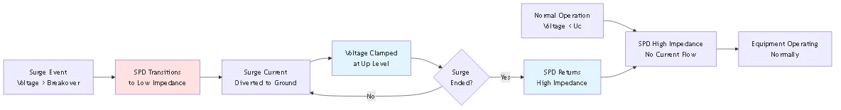
Surge protection devices operate as voltage-dependent switches, remaining in high-impedance state during normal operation and rapidly transitioning to low-impedance when detecting overvoltage conditions. This transition diverts surge current away from protected equipment, routing it safely to ground. The SPD must then return to high-impedance state after the surge passes, restoring normal circuit operation without creating short circuits.
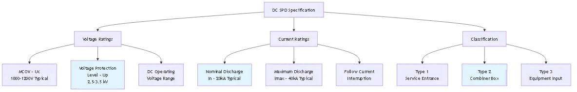
The primary function of any SPD is limiting the voltage experienced by protected equipment to levels below their damage threshold. This maximum voltage, called the voltage protection level (Up), represents the SPD’s most critical specification. For example, an inverter with a 1000V maximum input requires an SPD with Up below 1000V, typically 2.5-3.5 kV to provide adequate safety margin.
SPDs operate in microseconds, responding faster than conventional circuit protection devices. A lightning surge rises to peak current in 1-10 microseconds, too fast for circuit breakers or fuses. The SPD must clamp the voltage within the first microsecond to prevent damage to semiconductor components in inverters and charge controllers.
Energy absorption capacity determines how much surge energy the SPD can dissipate without failure. This parameter, measured in kilojoules (kJ), depends on component size and thermal mass. Repeated surge exposure degrades SPD components, eventually requiring replacement when protection capacity diminishes below safe levels.
💡 Approfondimento chiave: Think of a DC SPD as a lightning rod for your electrical circuit—it provides a preferential path for surge energy, protecting valuable equipment by sacrificing itself when necessary.
Metal Oxide Varistors (MOVs) form the core of most DC SPDs, providing voltage-dependent non-linear resistance. These ceramic semiconductor devices exhibit high resistance at normal operating voltage and rapidly decrease to low resistance when voltage exceeds a specific threshold. MOV technology offers excellent surge energy absorption, fast response time, and cost-effectiveness for PV applications.
The MOV structure consists of zinc oxide grains with intergranular boundaries forming microscopic PN junctions. At low voltages, these junctions block current flow. When surge voltage exceeds the junction breakdown voltage, all junctions conduct simultaneously, creating a low-resistance path. This avalanche effect occurs in nanoseconds, providing nearly instantaneous protection.
Silicon avalanche diodes (SADs) provide more precise voltage clamping than MOVs, offering tighter Up tolerances and longer service life. SADs work well for lower surge currents in sensitive electronics protection but cost more than MOV-based designs. Hybrid SPDs combine MOVs for high-energy surges with SADs for precision voltage limiting.
Gas discharge tubes (GDTs) handle extremely high surge currents but exhibit slower response times and higher clamping voltages than MOVs. GDTs find application in multi-stage SPD designs as the first stage to dissipate bulk surge energy before MOVs provide final voltage clamping. The GDT arc extinguishes naturally when surge current drops below the holding current.
| SPD Technology | Tempo di risposta | Surge Current Capacity | Primary Application |
|---|---|---|---|
| Metal Oxide Varistor (MOV) | < 25 nanoseconds | 20-100 kA | General PV surge protection |
| Silicon Avalanche Diode (SAD) | < 1 nanosecond | 1-5 kA | Sensitive electronics protection |
| Gas Discharge Tube (GDT) | 100-300 nanoseconds | 40-200 kA | First-stage high-energy protection |
| Hybrid (MOV + SAD) | < 25 nanoseconds | 10-40 kA | Premium protection systems |
IEC 61643-31 defines three SPD classes based on installation location and surge protection capability. Type 1 SPDs install at the service entrance, handling direct lightning strikes with maximum discharge currents up to 100 kA. These devices feature robust construction with spark gaps or heavy-duty varistors capable of surviving extreme surge energy.
Type 2 SPDs protect at distribution boards and combiner boxes, addressing induced surges from nearby lightning strikes and switching transients. Rated for 20-40 kA discharge current, Type 2 devices represent the most common selection for PV combiner box protection. They prevent surges propagating from combiner locations to inverters through DC cabling.
Type 3 SPDs provide point-of-use protection for individual equipment like inverters or charge controllers. With 5-10 kA ratings, these devices offer final voltage clamping close to sensitive electronics. Type 3 installation requires coordination with upstream Type 2 devices through proper conductor length separation.
The classification system ensures appropriate SPD selection matching threat levels at different system locations. External lightning protection systems require Type 1 capability, while internal distribution systems work effectively with Type 2 protection. Using undersized SPD types results in premature failure and inadequate equipment protection.
⚠️ Importante: Installing Type 2 SPDs where Type 1 devices are required creates serious safety hazards. Always evaluate lightning exposure and consult IEC 62305 lightning protection zone concepts when selecting SPD classifications.
The voltage protection level (Up) represents the maximum voltage appearing at equipment terminals during surge events. Up depends on SPD component technology, surge current magnitude, and connection lead inductance. Lower Up values provide better equipment protection but require more expensive SPD components with tighter manufacturing tolerances.
Maximum Continuous Operating Voltage (MCOV or Uc) defines the highest voltage the SPD can withstand continuously without degradation. For 1000V PV systems, typical MCOV ratings are 1000-1200 VDC, providing margin above normal operating voltages including temperature effects. Selecting SPDs with insufficient MCOV leads to premature aging and thermal runaway.
The ratio between Up and MCOV indicates protection quality. Premium SPDs achieve Up/MCOV ratios of 2.5:1 or better, meaning a 1000V MCOV device clamps at 2500V or less. Standard SPDs may exhibit 3.5:1 ratios. Closer ratios provide superior protection but require more sophisticated varistor formulations.
Temperature affects both MCOV and Up parameters. MOV resistance decreases with temperature, reducing both breakdown voltage and clamping voltage. Manufacturers specify ratings at 25°C with derating factors for elevated temperatures. Combiner boxes in desert climates may experience 70°C internal temperatures, requiring careful specification review.
Nominal discharge current (In) represents the surge current waveshape used for SPD testing and classification. IEC standards use 8/20 μs waveshape: current rises to peak in 8 microseconds and decays to 50% in 20 microseconds. This waveshape simulates typical lightning-induced surges in electrical systems. Type 2 SPDs are tested at In=20 kA, meaning they must survive multiple surges of this magnitude.
Maximum discharge current (Imax) defines the largest single surge the SPD can withstand without catastrophic failure. Imax typically rates 2-3 times higher than In. A Type 2 SPD with In=20 kA might specify Imax=40 kA, providing safety margin for extreme surge events. Exceeding Imax destroys the SPD, potentially creating open or short circuit conditions.
Surge current magnitude depends on lightning stroke characteristics and system impedance. Direct strikes to building structures produce 50-200 kA currents at the strike point, but distribution through multiple ground paths reduces individual circuit exposure. Induced surges from nearby strikes typically generate 5-20 kA currents in PV systems.
The number of surge operations an SPD survives before degradation depends on surge magnitude relative to In rating. An SPD may survive dozens of In-level surges but only one or two Imax surges. Frequent surge exposure in high-lightning-activity regions may require more frequent SPD inspection and replacement.
DC arc interruption presents significant challenges compared to AC protection. AC voltage naturally crosses zero 120 times per second (60 Hz), extinguishing any arc formation. DC maintains constant polarity, allowing arcs to sustain indefinitely once established. DC SPDs require additional arc-quenching features like magnetic blow-out coils or specialized spark gap designs.
PV systems generate voltage while exposed to sunlight, unlike AC circuits that depend on external utility supply. A failed SPD creating a short circuit in an AC system stops receiving current when the breaker trips. In a PV system, the arrays continue generating voltage and current, potentially sustaining arcs or overheating failed SPD components. This characteristic mandates SPD designs with internal disconnection capability.
DC system voltage varies with temperature and irradiance, affecting SPD selection. Open-circuit voltage (Voc) at cold temperatures may exceed 1.25 times standard test condition (STC) voltage. SPDs must have MCOV ratings exceeding maximum expected Voc, typically 1200V MCOV for systems nominally 1000V. AC SPDs experience relatively constant voltage magnitude.
Polarity considerations affect DC SPD installation. Positive-to-ground and negative-to-ground surges require protection, typically achieved with SPD modules on both conductors. Some DC systems use negative grounding for corrosion control, affecting the required SPD configuration compared to ungrounded or positive-grounded systems.
NEC Article 690.35 addresses surge protection requirements for PV systems. While not mandating SPD installation, the code provides specifications when SPDs are used. The SPD must be listed for DC application, with voltage and current ratings appropriate for the system. Installing non-DC-rated SPDs violates code and creates fire hazards.
SPD grounding conductor sizing follows NEC 690.35(C), requiring minimum #14 AWG for protected circuits under 30A and #10 AWG for circuits 30-60A. The grounding conductor should be as short and straight as possible, avoiding loops that add inductance. Each additional foot of lead length can add 30-50V to the voltage protection level due to inductive voltage drop.
Disconnection requirements per NEC 690.35(D) mandate that SPDs include internal disconnection or have external disconnect switches. This provision ensures that failed SPDs can be isolated without disrupting system operation. Many modern SPDs include thermal disconnectors that automatically separate failed varistors from the circuit.
Accessible SPD placement facilitates inspection and replacement. NEC doesn’t specify maximum mounting height, but practical maintenance requires locations reachable without special equipment. Combiner boxes and disconnect enclosures provide natural SPD mounting locations. Some installations use dedicated SPD enclosures near the combiner or inverter.
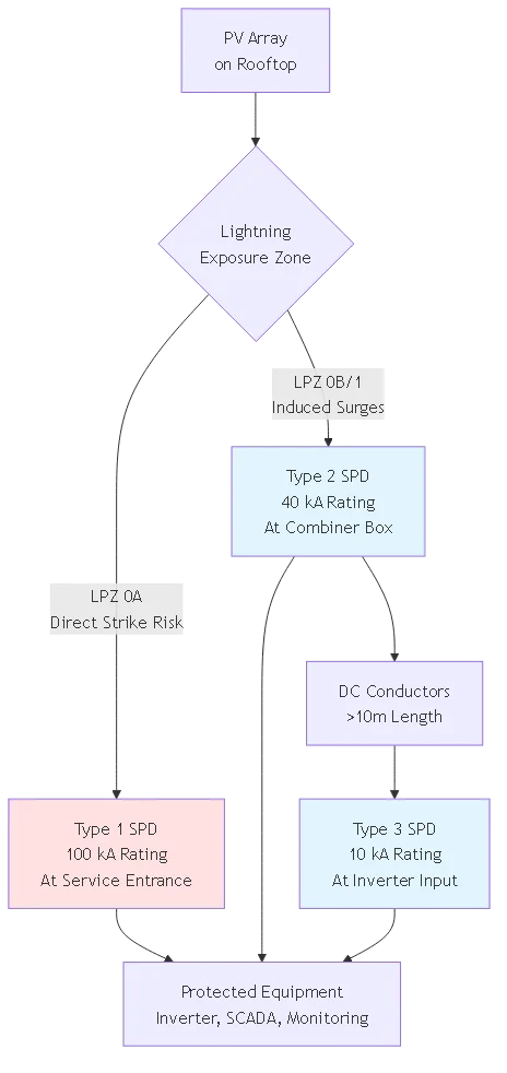
Multi-stage SPD protection uses Type 1 devices at service entrance, Type 2 at mid-level distribution, and Type 3 at equipment inputs. Proper coordination requires sufficient conductor length between stages, typically 10-15 meters, allowing impedance to divide surge current between stages. Insufficient separation causes stages to operate simultaneously, negating the staged protection benefit.
Energy coordination ensures upstream SPDs absorb bulk surge energy before downstream devices respond. The Type 1 SPD handles 80-90% of surge energy, Type 2 captures 10-15%, and Type 3 provides final cleanup. This division prevents any single SPD from overwhelming, extending service life across all protection stages.
Voltage coordination maintains Up levels at each stage consistent with protected equipment ratings. The Type 3 SPD Up must be lowest, protecting sensitive inverter electronics. Type 2 Up can be 10-20% higher, and Type 1 Up highest still. This cascading voltage protection ensures each stage activates at appropriate thresholds.
Installation errors like paralleling SPDs without proper derating can cause protection failure. Two identical SPDs in parallel don’t provide 2× protection capacity—unequal impedance causes one SPD to conduct more current and fail first. Manufacturers offer multi-channel SPDs with matched components for proper parallel operation.
🎯 Suggerimento per i professionisti: Document SPD installation dates and surge counter readings (if available) to track exposure history. Replace SPDs every 5-7 years in high-lightning areas even without visible failure indicators.
SPD degradation occurs gradually through repeated surge exposure or suddenly from exceeding Imax rating. Gradual degradation increases leakage current, raising SPD temperature. Thermal runaway occurs when leakage current heating further reduces MOV resistance, creating a positive feedback loop ending in thermal destruction.
Visual indicators provide SPD status feedback without requiring test equipment. Green LED or indicator windows show normal operation, yellow indicates degradation with remaining partial protection, and red or missing indicators signal failed status requiring immediate replacement. These indicators typically connect to internal thermal disconnectors or varistor degradation sensors.
Remote monitoring capability allows SCADA systems to track SPD status in utility-scale installations. Dry contacts or relay outputs signal SPD failure to monitoring systems, enabling proactive maintenance. Some advanced SPDs provide analog signals indicating cumulative surge energy absorbed, predicting remaining service life.
Catastrophic SPD failure can create short circuits if thermal disconnection fails. This scenario emphasizes the importance of proper SPD coordination with upstream overcurrent protection. The circuit breaker or fuse upstream of the SPD must be sized to clear SPD short circuit faults without creating arc flash hazards.
Problema: AC SPDs lack DC arc interruption capability, potentially sustaining arcs after surge events and creating fire hazards.
Scenari comuni:
– Installing residential AC SPDs in solar combiner boxes
– Assuming higher AC current ratings provide adequate DC protection
– Using whatever SPD is in stock without checking DC certification
Correzione: Always verify DC rating on the SPD label and listing information. UL 1449 Ed.4 requires separate DC ratings. Check for DC voltage rating equal to or exceeding system maximum Voc at lowest temperature.
Problema: Long grounding conductors add inductance, increasing the voltage protection level and reducing SPD effectiveness.
Scenari comuni:
– Routing SPD ground through conduit with other conductors
– Creating loops in grounding conductors for neat appearance
– Using undersized wire requiring longer routing paths
Correzione: Install SPD within 12 inches of busbar or connection point when possible. Route grounding conductor direct to grounding bus without loops. Use #6 AWG or larger for utility-scale systems even if code permits smaller.
Problema: SPD MCOV below system maximum Voc causes continuous varistor conduction, premature degradation, and thermal failure.
Scenari comuni:
– Selecting 600V SPD for systems with 600V STC rating (Voc may reach 750V cold)
– Ignoring temperature coefficient of PV module voltage
– Using utility-scale 1000V SPDs in 1500V systems
Correzione: Calculate maximum system Voc at -40°C using manufacturer temperature coefficients. Select SPD MCOV at least 1.1× maximum expected Voc. For 1000V STC systems, use 1200V or 1300V MCOV SPDs.
Problema: SPDs without internal thermal disconnect and no external isolation switch cannot be safely replaced during daytime when PV voltage is present.
Scenari comuni:
– Hard-wiring SPDs to busbars in combiner boxes
– Omitting dedicated SPD breaker or fuse
– Assuming SPD internal protection is sufficient
Correzione: Install fused disconnect or circuit breaker dedicated to SPD protection per NEC 690.35(D). Use SPD models with integral thermal disconnectors as first line of defense. Label disconnect clearly for maintenance personnel.
System voltage drives primary SPD selection: 600V systems require 600-800V MCOV SPDs, 1000V systems need 1000-1200V models, and 1500V systems demand 1500-1800V ratings. Always verify the MCOV exceeds maximum expected open-circuit voltage including temperature effects. Under-voltage rated SPDs fail prematurely from continuous overvoltage stress.
Installation location determines type classification: use Type 1 for service entrance with lightning protection systems, Type 2 for combiner boxes and mid-level distribution, Type 3 for final protection at inverter inputs. Most residential and small commercial PV installations use Type 2 SPDs exclusively. Large utility-scale plants may implement all three types in coordinated fashion.
Lightning exposure levels influence required current ratings. High-lightning areas (isokeraunic level >30 thunderstorm days/year) benefit from Imax ratings of 40-50 kA. Moderate exposure areas work adequately with 20-30 kA ratings. Coastal installations near salt water require corrosion-resistant SPD enclosures with NEMA 4X rating minimum.
Monitoring requirements affect SPD feature selection. Basic installations use visual indicators for manual inspection during maintenance visits. Advanced systems incorporate remote monitoring contacts integrated with SCADA systems. Critical installations may justify SPDs with surge counters recording event history for predictive maintenance.
Visual inspection schedules depend on lightning exposure and system size. Residential systems in moderate climates need annual inspections checking indicator status and looking for physical damage. High-exposure commercial installations benefit from semi-annual checks. Visual indicators showing degradation require immediate SPD replacement regardless of schedule.
Thermal imaging during inspections reveals SPDs with elevated operating temperatures indicating degradation. Normal SPD temperature should match ambient within 5-10°C. SPDs running 20-30°C above ambient show increased leakage current from MOV degradation. Temperature differences between SPD phases also indicate unequal degradation requiring replacement.
Post-surge inspections after known lightning events near the installation catch damage before complete SPD failure. Lightning within 500 meters warrants inspection regardless of visual indicator status. Check for discoloration, cracking, or melting of SPD housings. Test insulation resistance if indicators show normal but surge occurred nearby.
Replacement procedures require system shutdown in most cases since PV circuits remain energized during daylight. Schedule replacements for early morning or late evening when voltage is lowest. Use appropriate PPE including insulated gloves rated for system voltage. Verify new SPD specifications match original before installation.
Inverter replacement costs typically range from $0.20-0.40/watt for residential systems and $0.10-0.20/watt for utility-scale installations. A single 10 kW inverter replacement costs $2,000-4,000, while Type 2 SPD protection costs $150-300. The payback period for SPD investment is immediate when considering single lightning event protection.
Downtime costs exceed equipment costs in commercial installations. A commercial system producing $100-200/day in revenue loses $3,000-6,000 during a one-month repair delay. SPDs preventing damage eliminate these revenue losses. Insurance deductibles of $1,000-10,000 further improve SPD cost justification.
Extended equipment life provides secondary benefits. Inverters experiencing even non-destructive surge events accumulate damage over time, reducing reliability and shortening service life. SPD protection maintains clean power quality, extending equipment life 20-30% compared to unprotected installations.
Return on investment calculations should include avoided insurance claims and potential premium reductions. Some insurance carriers offer 5-10% premium discounts for installations with comprehensive surge protection. Over 20-year system life, these savings may equal or exceed initial SPD costs.
DC SPD stands for Direct Current Surge Protection Device. It protects solar PV systems and other DC equipment from voltage spikes caused by lightning strikes, switching transients, or grid disturbances. The SPD diverts surge current to ground while limiting voltage to safe levels, preventing damage to inverters, combiner boxes, and monitoring equipment. Unlike AC surge protectors, DC SPDs handle unique challenges of direct current including arc interruption and continuous voltage generation from PV arrays.
Type 1 SPDs protect against direct lightning strikes with 100 kA ratings and install at service entrances. Type 2 SPDs handle induced surges from nearby lightning with 20-40 kA ratings and install at combiner boxes or distribution panels. Type 3 SPDs provide final equipment protection with 5-10 kA ratings at inverter inputs. Most residential solar installations use Type 2 protection exclusively, while large commercial systems may implement all three types in coordinated layers.
Check the visual indicator on the SPD—green means operational, yellow indicates degradation, red signals failure. Inspect SPDs annually in moderate climates and semi-annually in high-lightning areas. Replace immediately if indicators show degradation or failure, if thermal imaging reveals elevated temperatures, or after nearby lightning strikes. Most SPDs last 5-7 years in typical installations but may require earlier replacement in high-surge environments or following extreme lightning events.
No. AC surge protectors lack DC arc interruption capability and cannot safely operate in DC circuits. DC maintains constant polarity unlike AC’s zero-crossing, allowing arcs to sustain indefinitely. AC-rated SPDs may fail catastrophically in DC applications, creating fire hazards. Always use SPDs specifically listed for DC use with appropriate voltage ratings. Check for UL 1449 Ed.4 DC certification and voltage ratings exceeding your system’s maximum open-circuit voltage.
For 1000V nominal systems (measured at Standard Test Conditions), select SPDs with 1200V or 1300V MCOV rating. This provides margin for voltage increase at cold temperatures—PV module voltage rises approximately 0.33% per degree below 25°C. At -10°C, a 1000V STC system may reach 1120V. Add safety margin for measurement uncertainty and module manufacturing tolerances. 600V nominal systems need 800V MCOV minimum, and 1500V systems require 1800V MCOV SPDs.
Install Type 2 SPDs at PV combiner boxes between the fuses and main circuit breaker, connecting positive and negative conductors to ground through the SPD. For systems without combiners, install SPDs at the inverter DC input terminals. Mount SPDs as close as possible to the connection point with grounding leads under 12 inches. Utility-scale systems add Type 1 SPDs at service entrance and Type 3 protection at inverter inputs, maintaining 10-15 meter separation between stages for proper coordination.
NEC Article 690.35 does not mandate SPD installation but provides requirements when SPDs are used. However, NEC 690.56(B) requires documentation of available fault current which often reveals lightning vulnerability prompting SPD specification. Many jurisdictions and insurance companies effectively require surge protection through permitting conditions or policy requirements. Industry best practice considers SPDs essential protection, not optional, given the high cost of unprotected equipment damage versus low SPD investment costs.
Ready to protect your solar investment with properly specified DC SPDs? Contact SYNODE’s technical team for system-specific SPD recommendations matching your installation’s voltage, lightning exposure, and protection requirements. We provide complete surge protection solutions meeting NEC Article 690 and IEC 61643 standards, backed by our electrical engineering expertise and 20+ years in PV protection equipment manufacturing.
Related Articles:
– DC SPD Wiring Diagram: Installation Best Practices
– Type 2 DC SPD Specifications and Selection Guide
– PV Surge Protection System Design Strategies
Parola chiave di riferimento: – **Primary Focus Keyword**: `what is dc spd`
URL Slug:
Meta Titolo: What is DC SPD? Surge Protection Device Fundamentals
Meta descrizione: What is DC SPD? Complete guide to DC surge protection devices: MOV technology, Type 1/2/3 classifications, voltage protection levels, and NEC requirements for solar PV systems.
Livello di contenuto: Livello 2 (Contenuto standard)
Funnel di conversione: Bottom of Funnel (Decision)
Conteggio parole obiettivo: 2800-4000 parole
Diagrammi della sirena target: 3
Configurarli nelle impostazioni di Rank Math, quindi eliminare questa casella prima della pubblicazione.
DC SPD stands for Direct Current Surge Protection Device. It protects solar PV systems and other DC equipment from voltage spikes caused by lightning strikes, switching transients, or grid disturbances. The SPD diverts surge current to ground while limiting voltage to safe levels, preventing damage to inverters, combiner boxes, and monitoring equipment.
Type 1 SPDs protect against direct lightning strikes with 100 kA ratings and install at service entrances. Type 2 SPDs handle induced surges from nearby lightning with 20-40 kA ratings and install at combiner boxes or distribution panels. Type 3 SPDs provide final equipment protection with 5-10 kA ratings at inverter inputs.
Check the visual indicator on the SPD—green means operational, yellow indicates degradation, red signals failure. Inspect SPDs annually in moderate climates and semi-annually in high-lightning areas. Replace immediately if indicators show degradation or failure, if thermal imaging reveals elevated temperatures, or after nearby lightning strikes.
No. AC surge protectors lack DC arc interruption capability and cannot safely operate in DC circuits. Always use SPDs specifically listed for DC use with appropriate voltage ratings. Check for UL 1449 Ed.4 DC certification and voltage ratings exceeding your system’s maximum open-circuit voltage.
For 1000V nominal systems, select SPDs with 1200V or 1300V MCOV rating. This provides margin for voltage increase at cold temperatures. At -10°C, a 1000V STC system may reach 1120V. 600V nominal systems need 800V MCOV minimum, and 1500V systems require 1800V MCOV SPDs.
Install Type 2 SPDs at PV combiner boxes between the fuses and main circuit breaker, connecting positive and negative conductors to ground through the SPD. For systems without combiners, install SPDs at the inverter DC input terminals. Mount SPDs as close as possible with grounding leads under 12 inches.
NEC Article 690.35 does not mandate SPD installation but provides requirements when SPDs are used. However, many jurisdictions and insurance companies effectively require surge protection through permitting conditions or policy requirements. Industry best practice considers SPDs essential protection given the high cost of unprotected equipment damage.