Endereço
304 North Cardinal
St. Dorchester Center, MA 02124
Horas de trabalho
De segunda a sexta-feira: das 7h às 19h
Fim de semana: 10:00 - 17:00
Endereço
304 North Cardinal
St. Dorchester Center, MA 02124
Horas de trabalho
De segunda a sexta-feira: das 7h às 19h
Fim de semana: 10:00 - 17:00

O disjuntor CC de 40 A ocupa um meio-termo crítico na proteção elétrica CC - grande o suficiente para controladores de carga solar significativos, alimentações principais de veículos recreativos e equipamentos marítimos, mas pequeno o suficiente para instalações residenciais econômicas. Essa classificação de amperagem aparece com frequência em sistemas de energia renovável e de energia móvel, tornando essenciais o dimensionamento adequado e o conhecimento da aplicação.
Este guia abrangente explora métodos de cálculo de carga, requisitos de dimensionamento de fios, considerações sobre queda de tensão e técnicas de instalação específicas para aplicações de disjuntores CC de 40A em sistemas elétricos solares fotovoltaicos, de veículos recreativos e marítimos.
O limite de 40 A representa os limites típicos de capacidade para vários aplicativos:
Controladores de carga solar:
- Controlador MPPT de 30A com fator de segurança NEC 125%: 37,5A → disjuntor de 40A
- Conjunto solar de 2400 W a 48 V: 2400 W ÷ 48 V = 50 A × 0,8 de eficiência = saída de 40 A
- Conjunto de 1600 W a 48 V: 33 A × 1,25 = 41 A → 40 A no mínimo
Sistemas elétricos para veículos recreativos:
- Saída do conversor de 12V: 480W ÷ 12V = 40A
- Alimentação principal de distribuição de 12 V da bateria
- Circuitos de aparelhos grandes (geladeira, ventilador de ar condicionado)
Aplicações marítimas:
- Bomba de pressão de água doce: 300W ÷ 12V = 25A × 1,25 = 31A → disjuntor de 40A
- Conjunto de eletrônicos de navegação: Carga combinada de 400W
- Circuito de controle do propulsor de proa (ciclo de trabalho baixo)
Industrial/Telecom:
- Racks de equipamentos de telecomunicação de 48V: 1500-1800W típico
- Circuitos de saída de sistemas UPS CC
- Distribuição de baterias de reserva
Artigo 210.19(A)(1) do NEC e 690.8(B) Requisitos:
Para cargas que operam continuamente (≥3 horas), a proteção do circuito deve ser classificada em um mínimo de 125% da corrente contínua:
Classificação necessária do disjuntor = corrente de carga contínua × 1,25Exemplo 1: Saída do controlador do controlador de carga solar: 30A contínuo Disjuntor necessário: 30A × 1,25 = 37,5A Selecione: Disjuntor de 40A (próximo tamanho padrão acima)
Exemplo 2: Bomba de água do trailer Corrente da bomba: 25A intermitente (<10 minutos por uso) Disjuntor necessário: 25A (sem fator 125% para intermitente) Selecione: Disjuntor de 30A ou 40A (40A oferece margem)
Por que 125% Fator de segurança:
1. Acúmulo de calor durante a operação prolongada
2. Variações de temperatura ambiente que afetam o ponto de disparo
3. Componentes envelhecidos (desvio do ponto de disparo para baixo)
4. Cargas simultâneas em condutores compartilhados
5. A queda de tensão aumenta o consumo de corrente
Método 1: classificação da placa de identificação (conservador)
Use as especificações da placa de identificação do equipamento:
Exemplo: Inversor solar
Placa de identificação: "Corrente máxima de entrada CC: 35A a 48V"
Cálculo: 35A × 1,25 = 43,75A
Selecione: Disjuntor de 50A
Observação: Fornece margem de segurança além da opção de 40A
Método 2: Corrente medida (precisa)
Use o alicate amperímetro CC em condições reais de operação:
Procedimento:
1. Prenda o medidor ao redor do condutor positivo
2. Opere o equipamento com a carga máxima esperada
3. Registre a corrente de pico por 10 minutos
4. Use o maior valor observado × 1,25
Exemplo de medição: Pico: 32A observado Disjuntor necessário: 32A × 1,25 = 40A (exatamente igual)
Método 3: Cálculo baseado em potência
Calcule a partir da potência e da tensão:
Corrente (A) = Potência (W) ÷ Tensão (V)Exemplo: Sistema solar de 48V Potência da matriz: 2000W Tensão do sistema: 48V nominal (corte de baixa tensão de 44V) Corrente de pior caso: 2000W ÷ 44V = 45,5A Disjuntor necessário: 45,5A × 1,25 = 56,9A → Selecione 60A
Observação: 40A é insuficiente para essa aplicação
Consideração de tensão crítica:
Sempre calcule a corrente com a tensão MAIS BAIXA do sistema:
Cálculo ERRADO:
2000W ÷ 48V = 41,7A × 1,25 = 52A → disjuntor de 60A
Cálculo CORRETO: Bateria LiFePO4 de 48V: - Nominal: 51,2V (16 células × 3,2V) - Limite de descarga: 40V (16 células × 2,5V)
Corrente no corte: 2000W ÷ 40V = 50A Necessário: 50A × 1,25 = 62,5A → disjuntor de 70A no mínimo
O uso de um disjuntor de 40 A dispararia prematuramente quando a bateria se esgotasse!
Várias cargas no mesmo circuito exigem soma:
Exemplo: Circuito de distribuição de 12V para veículos recreativos
- Luzes LED internas: 8A
- Bomba de água: 25A (quando estiver funcionando)
- Geladeira: 12A
- Ventilador do forno: 8A (quando em funcionamento)
Pior cenário possível (tudo ligado): Total: 8 + 25 + 12 + 8 = 53A
Verificação da realidade - Nem todos operam simultaneamente: - Luzes: Sempre possível - Bomba de água: Intermitente (rajadas de 1-2 minutos) - Geladeira: Ciclo de trabalho 30% - Forno: Ocasional
Carga simultânea realista: Luzes (8A) + Geladeira (12A) + uma outra (25A) = 45A Necessário: 45A × 1,25 = 56,25A → disjuntor de 60A
Alternativa: disjuntor de 40 A com gerenciamento de carga (impede a operação simultânea)
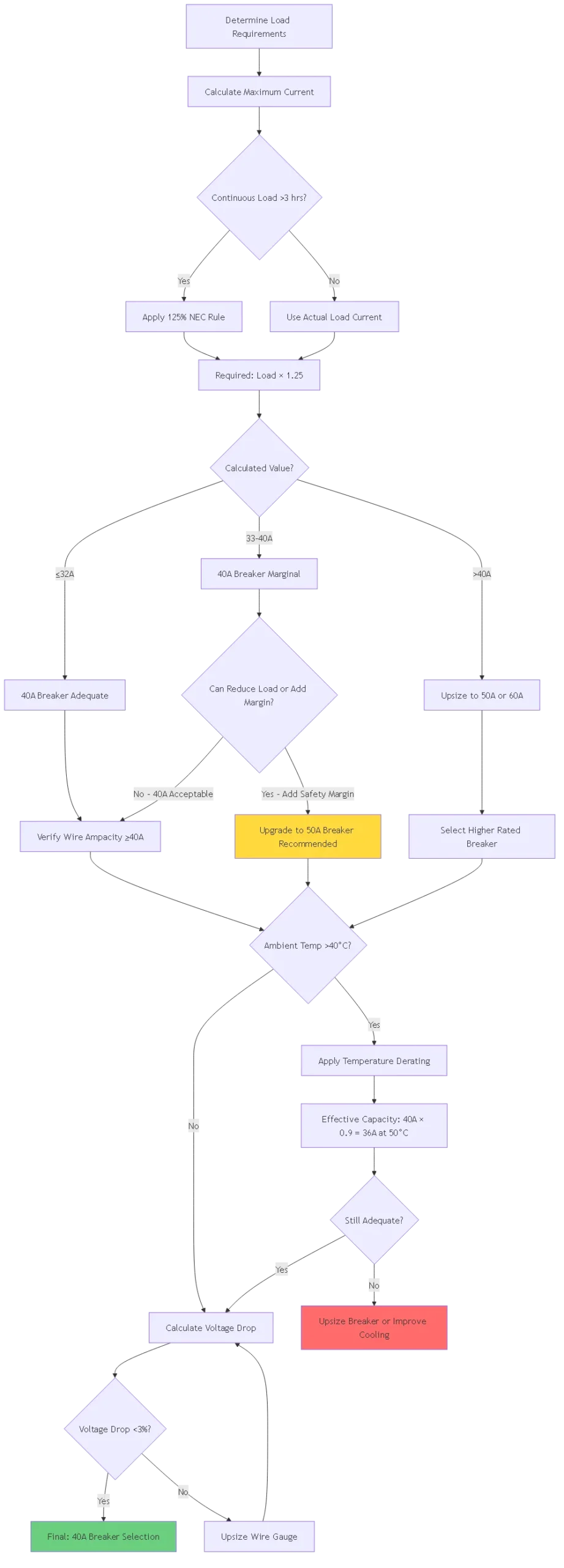
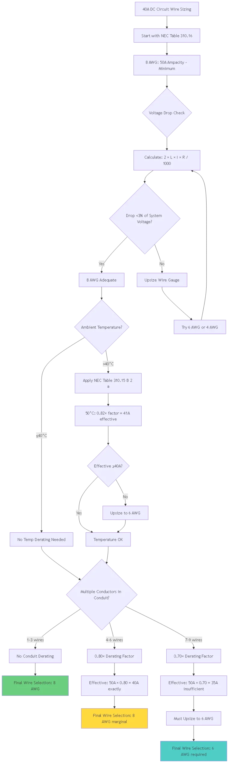
Tabela 310.16 do NEC (condutor de cobre de 75°C, ambiente de 30°C):
| Tamanho do fio | Ampacidade | Adequado para disjuntor de 40A? | Notas |
|---|---|---|---|
| 12 AWG | 25A | ❌ NÃO | Tamanho insuficiente - risco de incêndio |
| 10 AWG | 35A | ❌ NÃO | Abaixo do requisito de 40A |
| 8 AWG | 50A | ✅ SIM | Tamanho mínimo para disjuntor de 40A |
| 6 AWG | 65A | ✅ SIM | Preferencial (margem 25%) |
| 4 AWG | 85A | ✅ SIM | Tamanho grande (corridas longas, futuro) |
Regra crítica: A ampacidade do fio deve ser igual ou superior à classificação do disjuntor.
Por que 8 AWG, no mínimo:
Classificação do disjuntor: 40A
O fio deve suportar: ≥40A continuamente
Capacidade de 8 AWG: 50A (atende aos requisitos com a margem 25%)
Capacidade de 10 AWG: 35A (FALHA - o disjuntor não protegerá o fio!)
Em tensões CC (especialmente 12V), a queda de tensão afeta significativamente o desempenho:
Fórmula de queda de tensão:
Queda de tensão (V) = 2 × comprimento (pés) × corrente (A) × resistência do fio (Ω/1000 pés) / 1000Limites de queda aceitáveis: - Alimentadores: máximo de 2% (NEC 215.2(A)(1)) - Circuitos de derivação: Máximo de 3% (NEC 210.19(A)) - Combinados: Sistema total máximo de 5%
Exemplo de cálculo:
Aplicação: Controlador de carga solar de 48V
Corrente: 40A
Distância: 15 pés da bateria ao controlador
Fio: Cobre 8 AWG (0,628Ω por 1000 pés)
Queda = (2 × 15 × 40 × 0,628) / 1000 = 0,754V Porcentagem: 0,754V / 48V = 1,57% (ACEITÁVEL)
Se estiver usando 10 AWG (1,0Ω por 1.000 pés): Queda = (2 × 15 × 40 × 1,0) / 1000 = 1,2V Porcentagem: 1,2V / 48V = 2,5% (marginal, mas aceitável para esse circuito)
Exemplo de sistema de 12V (queda de tensão crítica):
Aplicação: Alimentação principal de RV 12V
Corrente: 40A
Distância: 20 pés
Fio: 8 AWG (0,628Ω por 1000 pés)
Queda = (2 × 20 × 40 × 0,628) / 1000 = 1,00V Porcentagem: 1,00V / 12V = 8,3% (EXCESSIVO!)
Solução - Aumente o tamanho para 4 AWG (0,249Ω por 1.000 pés): Queda = (2 × 20 × 40 × 0,249) / 1000 = 0,40V Porcentagem: 0,40V / 12V = 3,3% (aceitável)
Conclusão: os sistemas de 12 V exigem fios maiores do que os de 48 V para a mesma potência!
| Tensão do sistema | Atual | Distância máxima para queda de 3% | Tamanho mínimo do fio |
|---|---|---|---|
| 12V | 40A | 5 pés | 8 AWG |
| 12V | 40A | 10 pés | 6 AWG |
| 12V | 40A | 20 pés | 4 AWG |
| 24V | 40A | 10 pés | 8 AWG |
| 24V | 40A | 20 pés | 6 AWG |
| 24V | 40A | 40 pés | 4 AWG |
| 48V | 40A | 20 pés | 8 AWG |
| 48V | 40A | 40 pés | 6 AWG |
| 48V | 40A | 80 pés | 4 AWG |
Principais percepções: Os sistemas de tensão mais alta toleram fios mais longos antes de exigir um aumento de tamanho.
Fatores de correção de temperatura ambiente (Tabela 310.15(B)(2)(a) do NEC):
| Temperatura ambiente | Fator de correção | 8 AWG Capacidade efetiva |
|---|---|---|
| 30°C (86°F) | 1.00 | 50A |
| 40°C (104°F) | 0.91 | 45.5A |
| 50°C (122°F) | 0.82 | 41A |
| 60°C (140°F) | 0.71 | 35,5 A (insuficiente para 40 A!) |
Derivação do preenchimento do conduíte (Tabela 310.15(B)(3)(a) do NEC):
| Número de condutores | Fator de derivação | 8 AWG Capacidade efetiva |
|---|---|---|
| 1-3 | 1.00 | 50A |
| 4-6 | 0.80 | 40A |
| 7-9 | 0.70 | 35A (insuficiente para 40A!) |
Exemplo de redução combinada:
Cenário: fio 8 AWG em conduíte (5 condutores de corrente) em ambiente de 50°CRedução de temperatura: 0,82 Redução de conduíte: 0,80 Combinado: 0.82 × 0.80 = 0.656
Ampacidade efetiva: 50A × 0,656 = 32,8A
Resultado: 8 AWG insuficiente para o disjuntor de 40 A nessas condições Solução: Aumentar para 6 AWG (65A × 0,656 = 42,6A - adequado!)
Cenário: Controlador de carga MPPT de 30A para o banco de baterias
Especificações do sistema:
Controlador: saída máxima de 30A, 48V
Bateria: LiFePO4, 51,2 V nominal
Distância: 8 pés
Ambiente: 30°C (interior controlado)
Cálculo de dimensionamento:
Etapa 1: Aplicar a regra NEC 125%
30A × 1,25 = disjuntor mínimo de 37,5A
Selecione: Disjuntor de 40A ✓
Etapa 2: Dimensionamento do fio Mínimo: 8 AWG (capacidade de 50A > disjuntor de 40A) ✓
Etapa 3: Verificação da queda de tensão Queda = (2 × 8 × 30 × 0,628) / 1000 = 0,30V Porcentagem: 0,30V / 51,2V = 0,59% (excelente) ✓
Etapa 4: Redução da temperatura Ambiente 30°C: Nenhuma redução necessária (1,00×) ✓
Especificação final: - Disjuntor: 40A CC, classificação mínima de 80V - Fio: Cobre 8 AWG, classificação THWN-2 - Comprimento: Manter <10 pés para manter a baixa queda de tensão
Alternativa - Superdimensionamento para segurança:
Se, em vez disso, estiver fazendo upgrade para um disjuntor de 50A:
- Fornece uma margem de 67% sobre a carga de 30A (contra 33% com 40A)
- Permite atualização futura do controlador sem necessidade de refazer a fiação
- O fio continua sendo 8 AWG (adequado para disjuntor de 50A a essa distância)
- Diferença de custo: ~$15-20 a mais para o disjuntor
Recomendação: 40A adequado, 50A melhor para garantir o futuro
Cenário: Conversor de 12V CC que alimenta a bateria da casa e as cargas
Especificações do sistema:
Conversor: saída de 45A a 13,6V (carga flutuante)
Bateria doméstica: chumbo-ácido de 12V, 200Ah
Cargas: Combinadas, 35A no máximo, simultâneas
Distância: 12 pés do conversor ao painel de distribuição
Ambiente: 40°C (temperatura interna no verão)
Cálculo de dimensionamento:
Etapa 1: Análise de carga contínua
O conversor opera continuamente com energia da costa
45A × 1,25 = 56,25A mínimo
Selecione: Disjuntor de 60A (40A insuficiente!)
Aguarde - Verifique a carga real: Máximo de cargas simultâneas: 35A Capacidade do conversor: 45A Necessidade real: 45A × 1,25 = 56,25A
Ponto de decisão: o disjuntor de 40 A disparará se o conversor funcionar com sua capacidade máxima!
Opções: A) Usar disjuntor de 60A (protege a capacidade total do conversor) B) Usar disjuntor de 40A + gerenciamento de carga (limita as cargas a 32A)
Se escolher um disjuntor de 40A (opção econômica):
Etapa 2: Dimensionamento do fio para 40A
Mínimo: 8 AWG
Etapa 3: Queda de tensão (sistema de 12 V - crítico!) Queda = (2 × 12 × 40 × 0,628) / 1000 = 0,60 V Porcentagem: 0,60 V / 12 V = 5,0% (marginal, mas dentro do limite total do sistema de 5%)
Melhor opção - Aumentar para 6 AWG: Queda = (2 × 12 × 40 × 0,395) / 1000 = 0,38V Porcentagem: 0,38V / 12V = 3,2% (aceitável)
Etapa 4: Redução de temperatura 40°C ambiente: 0,91× fator 8 AWG: 50A × 0,91 = 45,5A efetivo (adequado para disjuntor de 40A) 6 AWG: 65A × 0,91 = 59A efetivo
Especificação final (com gerenciamento de carga): - Disjuntor: 40A CC, classificação de 32V - Fio: Cobre 6 AWG (melhor queda de tensão) - Gerenciamento de carga: Limite de cargas simultâneas a um máximo de 32A - Instale um cartaz: “Max Load 32A - Do Not Exceed” (Carga máxima 32A - Não exceder)”
Abordagem recomendada:
Use um disjuntor de 50A ou 60A em vez de 40A:
- Protege a capacidade total do conversor
- Não é necessário gerenciamento de carga
- Fios: 6 AWG ainda é adequado
- Instalação preparada para o futuro
Cenário: Controle do solenoide do propulsor de proa (serviço intermitente)
Especificações do sistema:
Motor do propulsor: 4000W a 12V (333A de corrente real do motor - disjuntor separado)
Solenoide de controle: 35A de partida, 18A de retenção
Distância: 25 pés do painel de controle ao compartimento do propulsor
Ciclo de trabalho: <30 segundos por uso, <2 minutos por hora
Ambiente: média de 30°C (local do porão)
Cálculo de dimensionamento:
Etapa 1: Carga intermitente - Não é necessário o fator 125%
Entrada do solenoide: 35A momentânea
Corrente de retenção: 18A contínua (mas <3 horas = intermitente)
Selecione o disjuntor com base na energização: faixa de 35-40A
Disjuntor de 40A adequado: - Não desarma com 35A de inrush (dentro da tolerância) - Protege o circuito de controle contra curtos-circuitos - Permite margem futura
Etapa 2: Dimensionamento dos fios Para o circuito de controle (não o circuito do motor): 35A × 1,25 (margem de segurança) = 43,75A Selecione: 8 AWG no mínimo
Etapa 3: Queda de tensão (12V, 25 pés) Queda = (2 × 25 × 35 × 0,628) / 1000 = 1,10V Porcentagem: 1,10V / 12V = 9,2% (EXCESSIVO para o controle do motor!)
Problema: A alta queda de tensão causa: - Redução da força de tração do solenoide - Possível falha na energização - Superaquecimento da bobina do solenoide
Solução - Aumentar o tamanho do fio: 4 AWG (0,249Ω por 1.000 pés): Queda = (2 × 25 × 35 × 0,249) / 1000 = 0,44V Porcentagem: 0,44V / 12V = 3,7% (aceitável)
Especificação final: - Disjuntor: 40A CC, classificação de 32V, termomagnético - Fio: Cobre 4 AWG, estanhado marítimo (resistência à corrosão) - Instalação: Conduíte flexível à prova de líquidos através do porão - Terminais: banhados a ouro ou aço inoxidável (ambiente marinho)
Classificação de tensão:
- Sistemas de 12V: Disjuntor nominal mínimo de 32V CC
- Sistemas de 24V: Disjuntor com classificação mínima de 50V CC
- Sistemas de 48V: Disjuntor com classificação mínima de 80V CC
Tipo de viagem:
- Térmico-magnético: Escolha padrão, $20-40
- Hidráulico-magnético: Ambientes quentes, $80-150
- Eletrônico: Configurações precisas, monitoramento remoto, $150-300
Classificação ambiental:
- Interno (NEMA 1): Serviço padrão
- Externo (NEMA 3R): Gabinete resistente a intempéries
- Marítimo (NEMA 4X): Resistente à corrosão, vedado
Etapa 1: Seleção do local
Requisitos:
- Acessível em 3 segundos (segurança)
- Altura: 4-6 pés acima do convés/piso
- Espaço de trabalho: 30" de largura × 36" de profundidade
- Preferencialmente em local seco (mesmo com disjuntor à prova de intempéries)
- Temperatura: Evite os compartimentos do motor, se possível
Etapa 2: Preparação do fio
Para fio 8 AWG (aplicação mais comum de 40A):
1. Retire 3/8" do isolamento
2. Crimpe o terminal de compressão (geralmente de tamanho amarelo)
3. Use um crimpador com catraca (não um alicate!)
4. Teste de puxar: Puxe com 30 lbs de força
5. Aplique o termorretrátil sobre a crimpagem
Etapa 3: Conexão do terminal
Especificações de torque para disjuntor de 40A:
- Terminais 8 AWG: 120-150 pol-lbs
- Terminais 6 AWG: 150-180 pol-lbs
- Terminais de 4 AWG: 180-220 pol-lbs
Procedimento: 1. Insira o terminal totalmente no terminal 2. Torque em etapas: 50% → 75% → 100% 3. Verifique se não há movimento 4. Marque com tinta de vedação de torque
Etapa 4: Teste
Pré-energização:
1. Teste de continuidade (disjuntor fechado): 1MΩ
3. Inspeção visual: Nenhum condutor exposto
Pós-energização: 1. Teste de tensão: Entrada = Saída (dentro de 0,2 V) 2. Teste de carga: Funcionamento com carga de 80% por 30 minutos 3. Varredura térmica: Temperatura do disjuntor <40°C acima da temperatura ambiente

Problema 1: O disjuntor dispara a 30-35A (abaixo da classificação de 40A)
Possíveis causas:
1. Alta temperatura ambiente (redução térmica)
2. Má ventilação ao redor do disjuntor
3. Conexões soltas que geram calor
4. Disjuntor envelhecido (desvio do ponto de disparo)
Etapas de diagnóstico:
1. Meça a corrente real com um alicate amperímetro CC
2. Verifique se a corrente é realmente 0,5V indica contatos ruins
Soluções:
- Melhorar a ventilação (adicionar ventilador se o gabinete for selado)
- Realocar o disjuntor para um local mais frio
- Reaperte todas as conexões
- Substituir o disjuntor antigo
- Aumente para um disjuntor de 50 A se o ambiente não puder ser melhorado
Problema 2: queda de tensão excessiva (>0,5 V no disjuntor)
Desempenho normal:
Disjuntor de 40 A com carga de 40 A: Queda aceitável de 0,2-0,3 V
Resistência interna: ~0,005-0,007Ω típico
Perda de energia: 40² × 0,006 = 9,6W (aceitável)
Indicadores de problemas:
Queda de tensão >0,5V a 40A
Resistência equivalente: 0,5V / 40A = 0,0125Ω (muito alta!)
Perda de energia: 40² × 0,0125 = 20W (calor excessivo)
Causas:
- Terminais corroídos (a oxidação aumenta a resistência)
- Conexões soltas (área de contato ruim)
- Degradação do contato interno
- Disjuntor subdimensionado para a aplicação
Soluções:
1. Desenergize completamente o circuito
2. Remova os fios dos terminais
3. Limpe os terminais:
   - Escova de arame ou ScotchBrite
   - Spray de limpeza de contatos elétricos
4. Limpe os terminais do disjuntor de forma semelhante
5. Aplique um composto antioxidante (Noalox)
6. Reconecte e aplique o torque adequado
7. Teste novamente a queda de tensão
8. Se ainda for excessiva: Substitua o disjuntor
Problema 3: O disjuntor não é reinicializado após o disparo
Sintomas:
- O botão é pressionado, mas não trava
- Clica, mas reabre imediatamente
- Preso na posição de disparo
Causas:
- A falha ainda está presente no circuito
- Falha mecânica da trava
- Bloqueio térmico (ainda muito quente)
- Mecanismo de disparo danificado
Procedimento de diagnóstico:
1. Desconecte completamente a carga da saída do disjuntor
2. Aguarde 15 minutos (resfriamento térmico)
3. Tente reiniciar sem carga
4. Se reiniciar: Problema de carga (curto-circuito ou sobrecarga)
5. Se não for reinicializado: Falha mecânica do disjuntor
Solução de problemas de carga: 1. Meça a resistência do positivo ao negativo (carga desconectada) 2. deve ser >100kΩ (infinito para a maioria dos circuitos) 3. se <1Ω: Curto-circuito na fiação ou no equipamento 4. Inspecione a fiação quanto a danos, atrito, isolamento comprimido
Mensalmente (marítimo/RV) ou trimestralmente (instalação fixa):
- Inspeção visual de corrosão
- Teste a operação de abertura/fechamento manual
- Verificar se os rótulos são legíveis
- Verifique se há calor ou odores incomuns
Anualmente:
- Verifique o torque de todas as conexões (150-180 pol-lbs para 8 AWG)
- Teste de resistência de isolamento (>1MΩ)
- Medição da queda de tensão na carga nominal
- Imagem térmica sob carga
- Limpe os terminais e reaplique o antioxidante
Ciclo de substituição de 5 anos:
- Ambientes marinhos: Substituir a cada 5-7 anos
- RV/móvel: Substituir a cada 7 a 10 anos
- Solar fixo: Substituir a cada 10-15 anos
- Aplicações de alto ciclo: Substituir a cada 3-5 anos
Blue Sea Systems 7226 - Montagem em superfície 40A
- Preço: $28-35
- Recursos: IP67, protegido contra ignição, sem disparo
- Tensão: 32V CC (sistemas de 12V/24V)
- Melhor para: Painéis externos para embarcações e trailers
Carling Technologies CA1-B0-24-640-1B1-C
- Preço: $35-45
- Recursos: Hidráulico-magnético, sem redução térmica
- Tensão: 32V DC
- Melhor para: Salas de máquinas de alta temperatura
Eaton/Bussmann CHM Série 40A
- Preço: $25-35
- Recursos: Montagem em trilho DIN, termomagnético
- Tensão: 125V DC
- Melhor para: Circuitos do controlador de carga solar
Mega-fusível 40A da Victron Energy (Alternativa ao disjuntor)
- Preço: $8-12 por fusível + suporte $60
- Observação: Fusível em vez de disjuntor (não reajustável)
- Melhor para: Instalações econômicas, proteção de backup
1. Um disjuntor de 40A é suficiente para uma carga contínua de 35A?
Sim, com a aplicação adequada da regra NEC 125%: 35A × 1,25 = 43,75A de capacidade necessária. Um disjuntor de 40A é insuficiente, segundo o código, para cargas contínuas reais (>3 horas). Entretanto, se a carga for intermitente ou se você puder verificar que ela nunca excede 32A contínuos (40A ÷ 1,25), então 40A é adequado. Para uma carga contínua legítima de 35A, aumente o tamanho para um disjuntor de 50A para conformidade com o código e confiabilidade. O disjuntor de 40A pode funcionar, mas ficará quente e disparará de forma incômoda em climas quentes.
2. Que tamanho de fio é necessário para um disjuntor CC de 40 ampères?
Mínimo de 8 AWG de cobre (a ampacidade de 50A excede o requisito do disjuntor de 40A). No entanto, considere a queda de tensão: Para sistemas de 12 V com mais de 10 pés, aumente o tamanho para 6 AWG ou até 4 AWG para manter a queda de tensão abaixo de 3%. Para sistemas de 48V, 8 AWG funciona bem até 20-25 pés. Sempre calcule a queda de tensão para o comprimento específico de seu trecho e a tensão do sistema - o fio subdimensionado desperdiça energia e reduz a vida útil do equipamento, mesmo que atenda aos requisitos de ampacidade.
3. Posso usar um disjuntor de 40A para proteger um controlador de carga de 50A?
Não, ele está subdimensionado. Um controlador de carga de 50 A requer 50 A × 1,25 = 62,5 A de classificação mínima do disjuntor por NEC 690.8. Selecione um disjuntor de 60A ou 70A. O uso de um disjuntor de 40 A causará disparos incômodos quando o controlador operar próximo à sua capacidade nominal, especialmente durante a fase de carregamento em massa. O disjuntor protege o fio contra sobrecorrente, mas deve ser dimensionado para a saída máxima do equipamento, não para a limitação desejada.
4. Como posso saber se meu disjuntor de 40 A está falhando?
Sinais de advertência: (1) Disparos abaixo de 40A repetidamente, (2) Não reinicia após o período de resfriamento, (3) Queda de tensão excessiva no disjuntor (>0,5V na carga nominal), (4) Muito quente ao toque (>60°C acima da temperatura ambiente), (5) Corrosão ou descoloração visível, (6) O teste de resistência mostra >0,01Ω quando fechado. Teste com alicate amperímetro CC para verificar a corrente real, câmera térmica para verificar as conexões e voltímetro para medir a queda de tensão. Se o disjuntor falhar em qualquer teste, substitua-o imediatamente - não espere pela falha completa, que pode causar incêndio.
5. Qual é a diferença entre um fusível automotivo de 40A e um disjuntor de 40A?
Os fusíveis respondem mais rapidamente (<0,1 segundo) e com mais precisão (±10% vs. ±20% para disjuntores), mas devem ser substituídos após a operação. Os disjuntores são reinicializáveis, lidam melhor com sobrecargas repetitivas e oferecem proteção com retardo de tempo (disparo térmico de 5 a 60 segundos). Para circuitos de segurança críticos (desconexão de bateria, supressão de incêndio), use fusível. Para circuitos de conveniência que podem ocasionalmente sofrer sobrecarga (bombas, motores), use o disjuntor. Muitos sistemas usam ambos: disjuntor como proteção primária e fusível como backup. Os fusíveis custam $5-15, mas precisam de peças de reposição; os disjuntores custam $25-45, mas duram mais de 10 anos.
6. Posso colocar dois disjuntores de 40A em paralelo para obter uma capacidade de 80A?
Não, nunca coloque disjuntores em paralelo. Mesmo os disjuntores “idênticos” têm pequenas diferenças de resistência interna (±10%), causando uma distribuição desigual da corrente. Um disjuntor carregará 45A enquanto o outro carregará 35A, fazendo com que o disjuntor sobrecarregado desarme primeiro. Quando ele se abre, o disjuntor remanescente vê subitamente 80A e desarma imediatamente. A ligação em paralelo anula totalmente a proteção contra sobrecorrente. Em vez disso, use um único disjuntor classificado para a corrente total (80A) ou coloque os condutores em paralelo usando um disjuntor com a classificação adequada.
7. Preciso de um disjuntor de 40 A com classificação CC ou posso usar um com classificação CA?
Você DEVE usar disjuntores com classificação CC para circuitos CC. Os disjuntores CA dependem do cruzamento zero natural da corrente alternada (120 vezes/segundo a 60 Hz) para extinguir os arcos. A CC não tem cruzamento zero - os arcos se mantêm indefinidamente e podem soldar os contatos. Os disjuntores CC têm lacunas de contato maiores, bobinas magnéticas de descarga e calhas de arco para interromper com segurança a corrente CC. Um disjuntor CA em CC falhará de forma catastrófica durante uma condição de falha, podendo causar arco elétrico, incêndio ou explosão. Sempre verifique a marcação “CC” e a classificação de tensão na etiqueta do disjuntor.
O disjuntor CC de 40 A serve como um dispositivo de proteção versátil de médio porte para controladores de carga solar, sistemas de distribuição de veículos recreativos e equipamentos marítimos. O dimensionamento adequado requer uma análise cuidadosa da carga, aplicação da regra NEC 125% e verificação do dimensionamento dos fios.
Lista de verificação de seleção:
- Calcular a corrente de carga real (incluindo cenários de baixa tensão)
- [ ] Aplicar o fator 125% para cargas contínuas (>3 horas)
- Verificar se 40A é adequado ou aumentar para 50A/60A
- Tamanho do fio mínimo de 8 AWG (aumento de tamanho para queda de tensão)
- [ ] Verifique a redução da temperatura ambiente (preferencialmente <40 °C) - [ ] Calcule a queda de tensão (<3% para circuitos de derivação) - [ ] Selecione o disjuntor com classificação CC (nunca use disjuntor CA) - [ ] Escolha a classificação de tensão ≥ máximo do sistema (32 V para 12 V, 80 V para 48 V) Guia rápido de dimensionamento de fios:
- Sistemas de 12V: 6-4 AWG para percursos >10 pés
- Sistemas de 24V: 8-6 AWG típico
- Sistemas de 48V8 AWG: adequado para a maioria das instalações <25 pés Lembretes de instalação:
- Montar em um local acessível (com alcance de 3 segundos)
- Aperte os terminais adequadamente (150-180 pol-lbs para 8 AWG)
- Rotular o circuito claramente com a amperagem e a finalidade
- Teste antes e depois da energização
- Varredura térmica após 1 hora sob carga
Quando aumentar o tamanho para 50A ou 60A:
- A carga excede 32 A contínuos (40 A ÷ 1,25)
- Temperatura ambiente >50°C (redução significativa)
- Futuras atualizações de equipamentos planejadas
- A carga inclui alta corrente de inrush (motores, inversores)
- Margem de segurança extra desejada para circuitos críticos
A classificação de 40A oferece uma solução de proteção econômica para muitas aplicações residenciais e móveis de CC quando dimensionada e instalada adequadamente, seguindo as diretrizes da NEC e as especificações do fabricante.