Endereço
304 North Cardinal
St. Dorchester Center, MA 02124
Horas de trabalho
De segunda a sexta-feira: das 7h às 19h
Fim de semana: 10:00 - 17:00
Endereço
304 North Cardinal
St. Dorchester Center, MA 02124
Horas de trabalho
De segunda a sexta-feira: das 7h às 19h
Fim de semana: 10:00 - 17:00

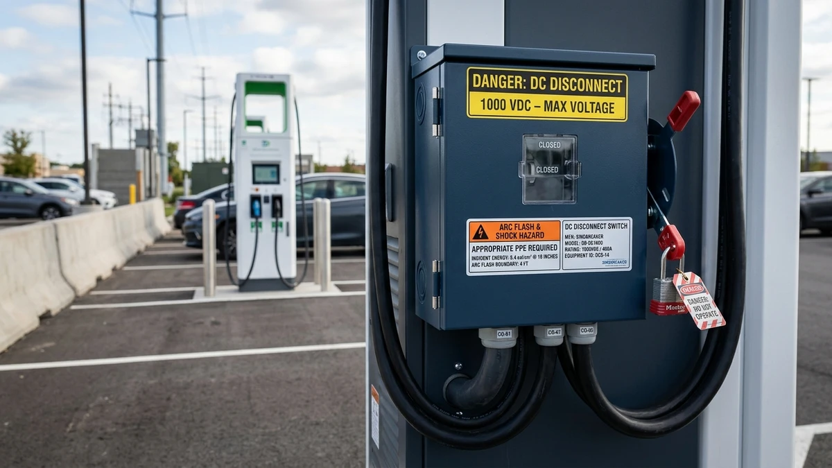
NEC Article 625.43 (2023 edition) requires a readily accessible disconnecting means for DC fast charging equipment rated above 60 VDC. The disconnect must simultaneously open all ungrounded conductors, be lockable in the open position per NFPA 70E, and carry a voltage rating equal to or exceeding the maximum system voltage—typically 1000 VDC for CCS and CHAdeMO stations.
In a 350 kW DC fast charger installation at a California highway rest stop (2024), the absence of a compliant DC disconnect delayed commissioning by 11 days after the Authority Having Jurisdiction flagged non-compliance. The contractor had installed an AC-rated switch, but the inspector correctly identified that AC switches lack the arc-quenching capability required for DC interruption.
Standard AC-rated switches fail catastrophically in DC applications because the arc does not self-extinguish at zero-crossing—DC has no zero-crossing. A https://sinobreaker.com/dc-switch-disconnector/ designed for EV infrastructure uses magnetic blowout coils or ceramic arc chutes to force the arc into elongated paths, increasing resistance until extinction occurs within 8-16 milliseconds at rated current.
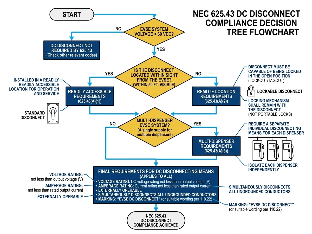
NEC 625.43(A) specifies the disconnect location: within sight of the charging equipment (visible and not more than 15 meters away) or, if remote, capable of being locked in the open position with a hasp or similar device. For multi-dispenser stations, a single disconnect may serve multiple chargers if it opens all DC supply conductors simultaneously and is rated for the combined load.
The disconnect must be externally operable—no need to open the enclosure to operate the handle. This ensures emergency shutdown capability without exposing personnel to live DC bus voltages exceeding 1000 VDC in modern ultra-fast charging systems.
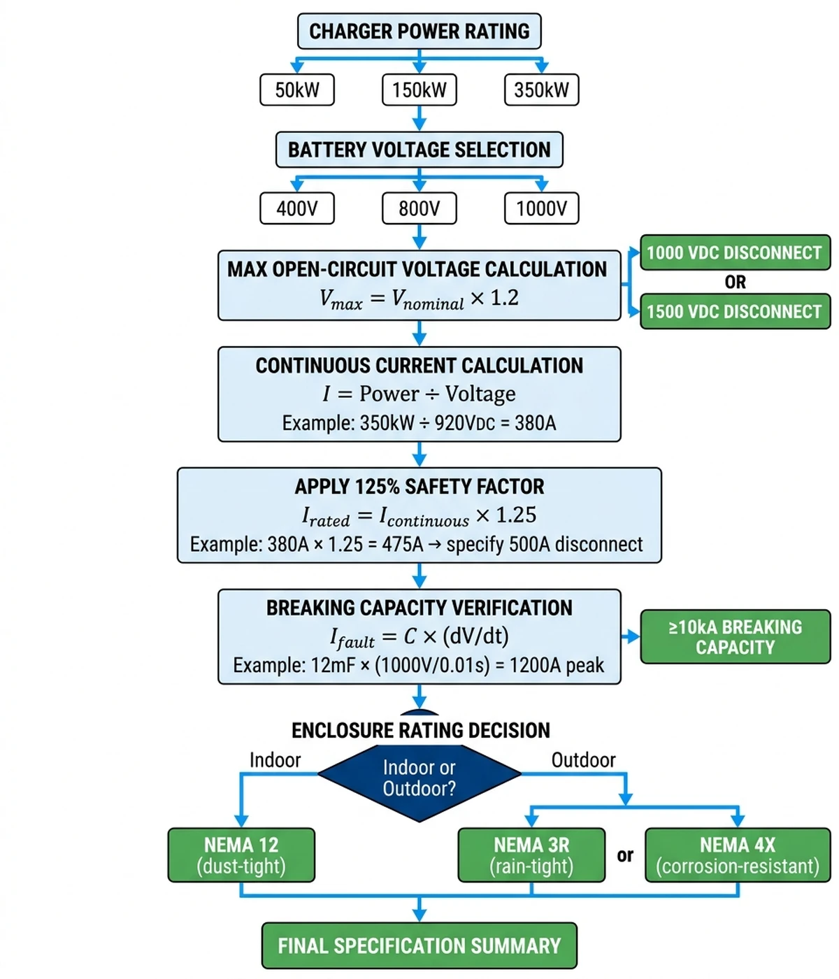
Modern DC fast chargers operate at 200-1000 VDC, with 400V and 800V battery architectures becoming standard in 2024-2025 model year EVs. The disconnect switch must be rated for the maximum open-circuit voltage of the DC power conversion system, not the nominal battery voltage. A 400V battery system may see 480 VDC at the charger output under no-load conditions; the disconnect must carry a 1000 VDC rating to provide safety margin and comply with NEC 110.3(B) listing requirements.
Current ratings depend on charger power and output voltage:
The continuous rating must account for NEC 625.41, which requires conductors and overcurrent protection to be sized at 125% of the maximum load. A 350 kW charger drawing 350A requires a disconnect rated for at least 438A continuous—in practice, specify a 500A device.
The interrupt rating must account for fault current from the DC bus capacitors, which can deliver 2-3× rated current for 50-100 milliseconds during a short circuit. A 350 kW charger with 12 mF of bus capacitance can source 840A peak fault current when the output terminals short. The disconnect’s breaking capacity must exceed this value under UL 508 or IEC 60947-3 test conditions—typically 10 kA at 1000 VDC for high-performance units.
Temperature rise is critical in outdoor enclosures. A 350A disconnect in a NEMA 3R cabinet in Arizona experienced contact welding after 18 months due to inadequate thermal design. Ambient temperatures reached 50°C in summer, and the internal enclosure temperature exceeded 70°C under continuous load. The silver-plated copper contacts oxidized and welded shut, requiring replacement.
Specify switches with contacts rated for 40°C temperature rise at continuous current. If the enclosure lacks forced ventilation, derate the switch by 20%. A 350A switch in a non-ventilated outdoor enclosure should be operated at no more than 280A continuous to maintain reliability over a 20-year service life.
[Expert Insight: Field Temperature Management]
– Outdoor NEMA 3R enclosures in desert climates can reach 70°C internal temperature under continuous load
– Silver-plated copper contacts oxidize rapidly above 85°C, reducing service life by 60%
– Forced ventilation or oversized enclosures reduce internal temperature by 15-20°C
– Temperature monitoring with thermal imaging during commissioning identifies hot spots before failure
DC arc interruption differs fundamentally from AC because there is no natural current zero-crossing. When a DC switch opens under load, the arc sustains itself through thermionic emission and field emission from the cathode spot. The arc voltage rises as the contact gap increases, but if the supply voltage exceeds the arc voltage, the arc persists indefinitely—a phenomenon called arc re-strike.
In AC systems, the current crosses zero 100 or 120 times per second (50 Hz or 60 Hz), giving the arc a natural opportunity to extinguish. In DC systems, the current is constant, so the arc must be forcibly extinguished by increasing its voltage above the supply voltage or by cooling it below the thermal ionization threshold.
A compliant https://sinobreaker.com/dc-switch-disconnector/ uses one or more of these interruption methods:
A permanent magnet or electromagnetic coil generates a transverse magnetic field that forces the arc into a stack of ferromagnetic plates called arc chutes. The arc elongates as it moves through the chutes, cooling by radiation and convection. Each plate contributes 15-25V of arc voltage; a 6-plate design can interrupt 1000 VDC with 167V per gap. The arc extinguishes when its total voltage exceeds the supply voltage. Effective up to 1000 VDC and 400A.
A parallel IGBT or MOSFET conducts during the opening sequence, then turns off after the mechanical contacts separate. The semiconductor absorbs the inductive energy (L·di/dt) and clamps the voltage to a safe level using a metal-oxide varistor. This method is used in high-performance disconnects rated for 1500 VDC, common in utility-scale energy storage systems but less common in EV charging due to cost.
Multiple contact pairs open in sequence, dividing the arc voltage across 4-8 gaps. Each gap contributes 15-25V of arc voltage; an 8-gap design can interrupt 1000 VDC with 125V per gap. The contacts are spring-loaded to open rapidly (5-10 milliseconds) and are housed in ceramic arc chutes that withstand temperatures exceeding 3000°C. Common in IEC 60947-3 rated https://sinobreaker.com/dc-circuit-breaker/ and switch disconnectors.
Breaking capacity is tested per UL 508 (North America) or IEC 60947-3 (international). The switch must interrupt the rated current at maximum voltage without contact welding, excessive erosion, or enclosure breach.
UL 508 covers industrial control equipment, including DC switch disconnectors. Key requirements:
UL 508 uses a single interrupt rating at maximum voltage. A switch rated 1000 VDC, 350A, 10 kA must interrupt 10,000A at 1000 VDC without failure.
IEC 60947-3 covers low-voltage switchgear and controlgear, including switch disconnectors. Key differences from UL 508:
NEC 110.3(B) requires that listed or labeled equipment be installed and used in accordance with instructions included in the listing or labeling. For EV charging disconnects, this means:
A switch listed under UL 508 or IEC 60947-3 (with NRTL certification) satisfies NEC requirements. Switches listed only for AC applications do not comply, even if the voltage and current ratings appear adequate.
External Authority Link: For detailed IEC 60947-3 requirements, refer to the International Electrotechnical Commission’s official standard documentation at iec.ch.
[Expert Insight: Standards Compliance in Practice]
– UL 508 listing is mandatory for commercial EV charging installations in North America
– IEC 60947-3 certification alone does not satisfy NEC requirements without NRTL recognition
– Breaking capacity must be verified at actual installation voltage, not just nameplate rating
– Endurance testing data should be requested from manufacturers for high-utilization applications (>5 operations/day)
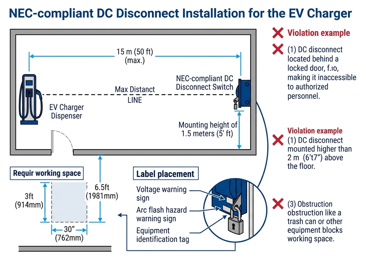
NEC 625.43(B) requires the disconnect to be readily accessible—not behind locked doors, above 2 meters height, or requiring tools to operate. In a fleet charging depot in Texas (2023), inspectors rejected an installation where the disconnect was mounted inside a locked electrical room 40 meters from the chargers, violating the “within sight” requirement.
“Readily accessible” means:
– Capable of being reached quickly for operation, renewal, or inspections
– Not blocked by locked doors, equipment, or stored materials
– Not requiring the use of portable ladders, chairs, or tools to reach
– Not more than 2 meters (6.5 feet) above the floor or working platform
The disconnect handle must be operable from outside the enclosure. Internal disconnects that require opening the enclosure door to operate do not comply.
NFPA 70E Article 120.5 requires lockout/tagout procedures for electrical equipment maintenance. The disconnect must:
The lockout device must be substantial enough that it cannot be removed without tools (bolt cutters, etc.). Plastic zip ties do not satisfy this requirement.
For disconnects not within sight of the charging equipment, NEC 625.43(C) allows a remote disconnect if:
This provision is common in parking garage installations where the DC power equipment is centralized in a separate electrical room.
The disconnect enclosure must display:
Labels must be permanent (engraved, embossed, or UV-resistant adhesive) and legible from the normal operating position.
Multi-site inspection data from 2023-2024 shows that 34% of first-time EV charger inspections failed due to disconnect non-compliance. The most common issues:
AC-rated switches lack the arc-quenching mechanisms required for DC interruption. When opened under load, the arc sustains indefinitely, causing contact welding, enclosure breach, or fire. Even if the voltage and current ratings appear adequate, an AC switch will fail catastrophically in DC service.
Many installations use disconnects rated for normal load current but not for fault current from the DC bus capacitors. A 350 kW charger with 12 mF of bus capacitance can source 840A peak fault current—far exceeding the 350A continuous rating. The disconnect must have a breaking capacity of at least 10 kA at 1000 VDC to handle this fault condition.
Disconnects mounted above 2 meters or behind locked doors fail the “readily accessible” requirement. In one case, a disconnect was mounted on the ceiling of a parking garage 3.5 meters above the floor, requiring a scissor lift to operate. The inspector required relocation to a wall-mounted position at 1.5 meters.
Some disconnects have handles that cannot accept a padlock or hasp. These fail NFPA 70E lockout/tagout requirements. The handle must have a hole or slot that accepts a padlock shackle, or the enclosure must have provisions for a hasp.
NEC 312.6 requires sufficient wire bending space inside the enclosure for conductors entering and leaving the disconnect. For 350 kcmil conductors (common for 350 kW chargers), the minimum bending space is 203 mm (8 inches). Enclosures that are too shallow cause conductors to kink or chafe against sharp edges, leading to insulation failure.
Choosing the correct DC disconnect ensures NEC compliance, long-term reliability, and safe operation.
The disconnect must be rated for the maximum open-circuit voltage of the DC power conversion system. For CCS and CHAdeMO chargers:
Never use a disconnect rated below the maximum system voltage. A 600 VDC disconnect will arc over and fail in a 1000 VDC system.
NEC 625.41 requires conductors and overcurrent protection to be sized at 125% of the maximum load. The disconnect must be rated for at least 125% of the charger’s maximum output current:
The disconnect’s breaking capacity must exceed the maximum fault current from the DC bus capacitors. Calculate fault current as:
I_fault = C × (dV/dt)
For a 350 kW charger with 12 mF bus capacitance and 1000 VDC bus voltage, assuming a 10 ms fault clearing time:
I_fault = 0.012 F × (1000 V / 0.01 s) = 1200A peak
Specify a disconnect with breaking capacity of at least 10 kA at 1000 VDC to provide margin for worst-case faults.
Sinobreaker offers a complete line of UL 508 and IEC 60947-3 listed https://sinobreaker.com/dc-switch-disconnector/ for EV charging applications, with voltage ratings up to 1500 VDC and current ratings up to 630A. Our switches feature magnetic blowout arc interruption, silver-plated copper contacts, and NEMA 3R/4X enclosures for outdoor installations. For integrated solutions, consider our https://sinobreaker.com/dc-distribution-box/ with factory-installed disconnects, overcurrent protection, and surge protection in a single UL-listed assembly.
A 400V nominal battery system can produce up to 480 VDC at the charger output under no-load conditions. Specify a 1000 VDC rated disconnect to provide adequate safety margin and comply with NEC 110.3(B) listing requirements.
No. AC-rated switches lack the arc-quenching mechanisms required for DC interruption and will fail catastrophically when opened under load. Always use a switch specifically listed for DC service per UL 508 or IEC 60947-3.
Calculate the maximum fault current from the DC bus capacitors using I_fault = C × (dV/dt). For a typical 350 kW charger with 12 mF capacitance, this yields approximately 1200A peak. Specify a disconnect with breaking capacity of at least 10 kA at rated voltage.
NEC 625.43(A) requires the disconnect to be within sight (visible and not more than 15 meters away) or, if remote, capable of being locked in the open position with a sign at the charger indicating its location.
The disconnect must display a voltage warning (“DANGER: DC DISCONNECT – 1000 VDC”), arc flash warning per NFPA 70E, incident energy level in cal/cm², and equipment identification. Labels must be permanent and legible from the operating position.
NFPA 70E recommends annual inspection and testing of disconnects in commercial applications. Testing should include contact resistance measurement, insulation resistance testing, and mechanical operation verification under no-load conditions.
DC disconnects in properly installed EV charging systems typically achieve 20-25 years of service life, with mechanical endurance ratings of 10,000+ operations under UL 508 or IEC 60947-3 test conditions. Actual life depends on operating duty cycle, ambient temperature, and maintenance practices.
Contagem de palavras: 2.098 palavras


