Endereço
304 North Cardinal
St. Dorchester Center, MA 02124
Horas de trabalho
De segunda a sexta-feira: das 7h às 19h
Fim de semana: 10:00 - 17:00
Endereço
304 North Cardinal
St. Dorchester Center, MA 02124
Horas de trabalho
De segunda a sexta-feira: das 7h às 19h
Fim de semana: 10:00 - 17:00

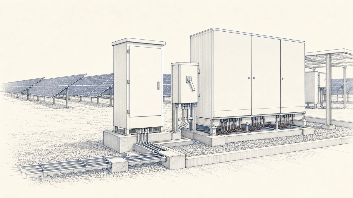
Emergency PV isolation design is not just the act of mounting a DC switch disconnector beside an inverter. In a photovoltaic system, the emergency isolation arrangement must be planned as part of the complete DC array, wiring route, power-conversion equipment, control interface, and service procedure.
For Sinobreaker applications, the DC Switch Disconnector should be selected and located so that trained personnel can isolate defined DC circuits safely, visibly, and repeatably. The final layout must always follow the authority having jurisdiction, the applicable local edition of the installation standard, and the instructions of the inverter, battery, optimizer, combiner, and shutdown-equipment manufacturers.
IEC 62548-1:2023 addresses PV-array design requirements, including DC array wiring, protection devices, switching, earthing provisions, and revised provisions for isolation means. This matters because emergency isolation is not a standalone switch-location choice. It is part of the PV array and the final power-conversion system.
IEC 60364-7-712:2025 applies to PV-system electrical installations from the modules to the connection point and includes installation requirements, including energy-storage considerations. In practice, this means the emergency isolation design must be coordinated across the whole installation rather than treated as a simple “put a switch near the equipment” decision.
A DC switch disconnector can isolate a defined DC circuit, but it does not automatically remove every PV-related hazard. PV modules may remain energized under light, conductors upstream of the disconnector may still be live, capacitors inside equipment may retain voltage for a period, and battery or backup interfaces may introduce additional energy paths.
Before selecting the disconnect location, define the isolation boundary:
This boundary should be documented on the single-line diagram and reflected in field labels. The emergency operator must be able to understand what the Sinobreaker DC Switch Disconnector isolates and what remains energized.
Emergency operation and maintenance isolation are related but not identical.
Emergency operation is usually intended for rapid access by firefighters, facility personnel, or trained responders. It may involve a visible actuator, remote emergency-stop input, fire-alarm interface, shutdown controller, inverter logic, and status indication.
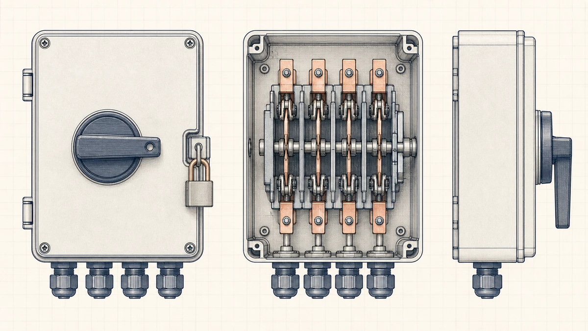
Maintenance isolation is usually performed by qualified electrical personnel who need a secure isolation point for testing, inspection, replacement, or repair. For this purpose, a DC switch disconnector should provide a clear open position, suitable DC ratings, and a lockable OFF position where required.
A good emergency PV isolation design does not assume one device satisfies every scenario unless the standard, local authority, and equipment manufacturer explicitly allow it.
The location of each DC switch disconnector should reduce exposure to live DC conductors, support intuitive emergency action, and allow safe service access. The right location depends on the array layout, cable routes, inverter position, building entry point, and whether rapid shutdown or remote emergency stop is required.
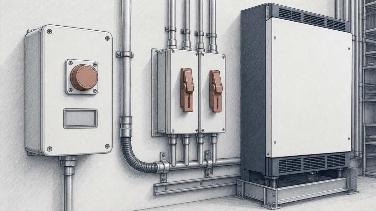
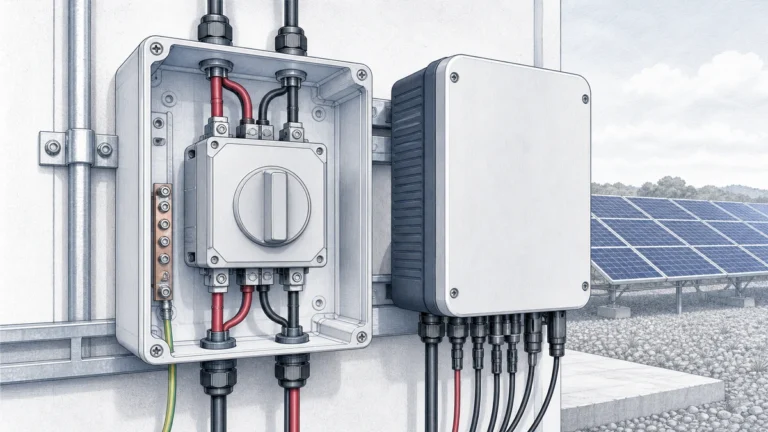
A common design principle is to locate a DC switch disconnector close to the equipment it isolates. For example, if the inverter DC input must be isolated for service, a Sinobreaker DC Switch Disconnector may be positioned near the inverter or integrated into the DC input path according to the system design.
This helps technicians verify the isolation point before opening equipment. It also reduces ambiguity when multiple arrays, inverters, or combiner boxes are installed on the same site.
However, placing a disconnect near the inverter does not necessarily de-energize DC wiring between the array and that disconnect. If conductors enter a building before reaching the switch, local rules may require additional measures, different routing, rapid shutdown, or an external emergency actuator.
Where PV DC conductors enter a building, emergency isolation design becomes more sensitive. The AHJ may require accessible isolation, controlled conductor routing, rapid shutdown, specific labeling, or a defined emergency switching sequence.
The designer should identify:
A DC switch disconnector located only inside a locked electrical room may be suitable for maintenance but insufficient for emergency access if the local code requires exterior operation or firefighter-accessible shutdown.
For emergency service, the disconnect operating handle should be easy to find, reach, and operate. Avoid locations blocked by parked vehicles, stored materials, landscaping, snow accumulation, locked tenant areas, or equipment that may be inaccessible during a fire event.
Good placement usually considers:
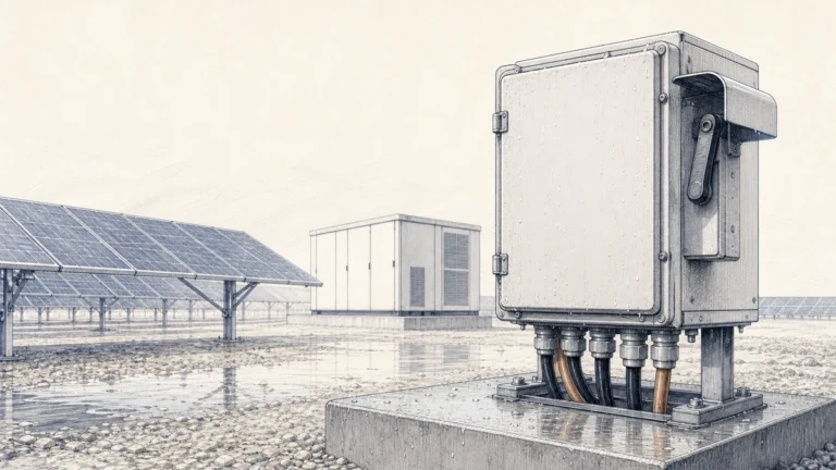
For outdoor installations, select a DC switch disconnector enclosure and mounting method suitable for UV exposure, rain, dust, temperature, and site conditions.
Modern PV systems often include shutdown functions beyond a manual DC isolator. SolarEdge’s Firefighter Gateway documentation, for example, describes manual emergency-stop and fire-alarm initiated shutdown as system-level functions. This supports treating the visible emergency actuator, control logic, shutdown equipment, and status indication as one verified sequence.
SolarEdge rapid-shutdown guidance also states that an external rapid-shutdown switch is required where regulations require it and that the external switch must be connected into the specified inverter or backup-interface architecture. The broader lesson applies across PV systems: emergency actuator placement and wiring must follow the exact system manufacturer’s instructions.
For Sinobreaker DC Switch Disconnector applications, this means the switch location should be coordinated with, not substituted for, the required rapid-shutdown or emergency-stop architecture.
Emergency PV isolation design should describe the sequence of action, not just the hardware list. The sequence should be understandable, testable, and repeatable.
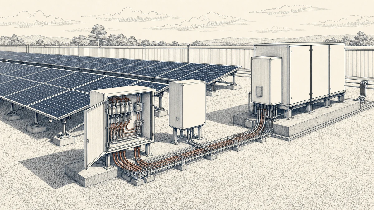
The emergency plan should define the first action clearly. Depending on the project and local rule, this may be:
The first action should be labeled in plain language. If multiple actions are required, the order must be documented and consistent with the equipment manufacturer’s instructions.
A safe-service design should define the expected final state after emergency isolation. This includes whether:
A DC switch disconnector gives physical isolation at its contacts, but voltage may remain on the supply side. Labels and diagrams must make this distinction clear.
Hidden energized DC conductors are one of the most important risks in PV emergency design. If a disconnect is located far from the array, the cable between the modules and the switch can remain live during daylight. If the switch is located near the array, the downstream route may be safer, but service at the inverter may require another isolation point.
Designers should minimize unnecessary live cable length and avoid routing live DC conductors through areas where emergency personnel may cut, ventilate, or access the building.
The DC switch disconnector must be suitable for the actual PV circuit. DC switching is more demanding than AC switching because DC arcs do not naturally cross zero. The device must be rated and installed for the system voltage, current, polarity, utilization category, and environmental conditions.
Check the maximum PV open-circuit voltage under the lowest expected temperature, not just the nominal string voltage. The selected DC switch disconnector should be rated for the maximum DC voltage and operating current of the circuit, with suitable margin according to the standard and manufacturer’s instructions.
Design checks should include:
Do not apply an AC-only disconnect to a PV DC circuit.
Some DC switch disconnectors have defined polarity or wiring direction requirements. Incorrect wiring can impair arc interruption performance. Follow the Sinobreaker wiring diagram and confirm terminal markings before energization.
Where multiple strings or MPPT inputs are present, label each circuit so service personnel can identify the source and destination without tracing cables under live conditions.
For maintenance, lockable OFF capability is often important. It helps prevent unintentional re-energization while qualified personnel are working on downstream equipment.
A lockable Sinobreaker DC Switch Disconnector should be installed so the OFF position is clear, the lock can be applied without defeating the enclosure rating, and the isolation point corresponds to the maintenance procedure.
Emergency isolation works only if the operator can understand the system quickly. Labels, diagrams, and test records are part of the design.
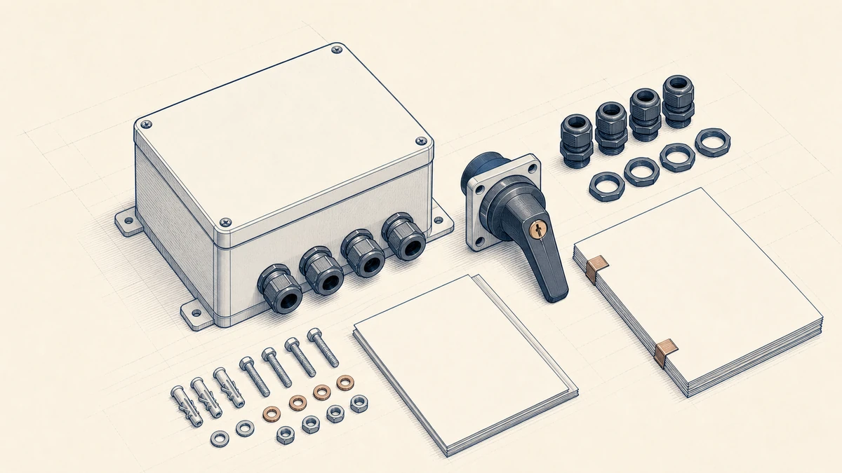
A useful disconnect label should state what is isolated and what remains live. For example:
“text“
PV DC DISCONNECT - INVERTER DC INPUT 1
OPENING THIS SWITCH ISOLATES THE INVERTER SIDE ONLY.
PV ARRAY CONDUCTORS ON LINE SIDE MAY REMAIN ENERGIZED IN DAYLIGHT.
The exact wording must match local code and AHJ requirements. Labels should be durable, legible, and located at the point of operation.
The site diagram should show:
This diagram should be available at the service location or other required posting point.
Commissioning should verify more than mechanical switch operation. The test should confirm that the complete emergency sequence performs as intended.
Recommended verification includes:
If a rapid-shutdown switch or fire-alarm interface is part of the system, it must be tested according to the manufacturer’s procedure and local requirements.
Use this checklist when planning emergency pv isolation design with a Sinobreaker DC Switch Disconnector:
No. A DC switch disconnector isolates the circuit section defined by its location and wiring. PV modules and upstream conductors may remain energized in daylight. In systems with rapid shutdown, batteries, optimizers, or backup interfaces, the complete emergency isolation sequence must be verified as a system.
The location depends on the PV array layout, cable routing, inverter position, building entry point, local code, and AHJ requirements. In many designs, disconnects are placed near the equipment being serviced, at accessible emergency locations, or at points required by local regulations. The final placement must follow the applicable standard edition and equipment manufacturer’s instructions.
Yes, when it is correctly rated and installed for the defined DC isolation function. However, it should not be assumed to replace a required rapid-shutdown switch or emergency-stop interface. Rapid-shutdown equipment must be connected and located according to the inverter or system manufacturer’s instructions and the local authority’s requirements.