Adresse
304 Nord Kardinal
St. Dorchester Center, MA 02124
Arbeitszeiten
Montag bis Freitag: 7AM - 7PM
Am Wochenende: 10AM - 5PM
Adresse
304 Nord Kardinal
St. Dorchester Center, MA 02124
Arbeitszeiten
Montag bis Freitag: 7AM - 7PM
Am Wochenende: 10AM - 5PM

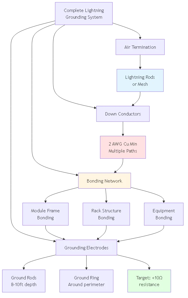
Die Blitzschutzerdung für Solaranlagen ist einer der wichtigsten, aber häufig missverstandenen Aspekte der Sicherheit von PV-Anlagen. Während Fangeinrichtungen Blitzeinschläge auffangen und Ableitungen den Strom sicher nach unten leiten, sorgt die Erdung für den entscheidenden letzten Schritt: Sie leitet Millionen von Ampere an Blitzenergie in die Erde ab, ohne gefährliche Spannungsanstiege zu erzeugen, die Geräte beschädigen oder Personen verletzen.
Die NFPA-Blitzschutznormen schreiben für gewerbliche Anlagen einen Erdungswiderstand von weniger als 10Ω vor. Feldstudien zeigen jedoch, dass 35-40% der Solarsysteme diesen Grenzwert aufgrund unsachgemäßer Installationstechniken, unzureichender Elektrodentiefe oder unzureichender Leiterdimensionierung überschreiten. Die Folgen gehen über fehlgeschlagene Inspektionen hinaus: Erdungssysteme mit hohem Widerstand verursachen bei Einschlägen einen Anstieg des Erdpotenzials (GPR), wodurch Spannungsdifferenzen von mehr als 10.000 V zwischen Geräten und Erde entstehen - genug, um Lichtbögen durch Wechselrichtergehäuse zu schlagen, Überwachungsgeräte zu zerstören und das Wartungspersonal zu erschüttern.
Dieser Installationsleitfaden erläutert die richtigen Erdungsmethoden speziell für den Blitzschutz von Solarmodulen. Sie erfahren, wie Sie die Dimensionierung des Erdungsleiters (EGC) pro NEC 690, Dazu gehören die Anforderungen an die Installation von Erdungsbrücken, die Platzierung von Erdungsstäben für einen optimalen Bodenkontakt, das Design von Erdungsringen für große Anlagen und Prüfverfahren, mit denen sichergestellt wird, dass abgeschlossene Installationen die Widerstandsziele erfüllen. Ob bei der Installation von Dachanlagen für Wohngebäude oder von Freiflächenanlagen für Versorgungsunternehmen - eine ordnungsgemäße Erdung schützt sowohl die Anlagen als auch Menschenleben.
💡 Kritische Einsicht: Die Blitzschutzerdung unterscheidet sich grundlegend von der Erdung elektrischer Anlagen - beide dienen unterschiedlichen Zwecken und erfordern oft separate Elektroden. Eine Verbindung der Blitzschutzerdung mit der Erdung der elektrischen Anlage ohne ordnungsgemäße Erdung kann bei Gewittern gefährliche zirkulierende Ströme erzeugen.
Die Blitzschutzerdung erfüllt drei wichtige Funktionen, die sich von der traditionellen Erdung des elektrischen Systems gemäß NEC Artikel 250 unterscheiden.
Energiedissipation: Blitzeinschläge liefern 20.000-200.000 Ampere in Mikrosekundenimpulsen. Diese Energie muss über Elektroden mit ausreichender Oberfläche in die Erde abgeleitet werden, um gefährliche Spannungsanstiege zu verhindern. Im Gegensatz zur stationären elektrischen Erdung, die mit Milliampere-Fehlerströmen zurechtkommt, bewältigt die Blitzableiter-Erdung massive transiente Ströme.
Steuerung des Spannungsgradienten: Bei einer Blitzentladung erfährt die Erde in der Nähe des Erdungspunkts Spannungsgradienten - Spannungsunterschiede je nach Entfernung. Unsachgemäß ausgelegte Systeme erzeugen “Stufenpotentiale”, bei denen die Füße einer Person die Erde mit unterschiedlichen Spannungen berühren, was zu einem Stromschlag führen kann, auch wenn man die Geräte nicht berührt. Eine ordnungsgemäße Erdung verteilt den Strom über weite Elektrodenbereiche und senkt die Gradienten unter gefährliche Schwellenwerte (<1000v per meter).Bezugspotenzial Einrichtung: Alle metallischen Systeme - Rahmen der PV-Module, Gestelle, elektrische Geräte - müssen mit einer gemeinsamen Erdungsreferenz verbunden werden. Dies verhindert Spannungsunterschiede zwischen den Komponenten bei einem Blitzschlag. Ein schwebender Modulrahmen, der 5 Meter von einem geerdeten Gestell entfernt ist, kann bei einem Blitzeinschlag in der Nähe eine Potenzialdifferenz von 50.000 V entwickeln, die einen Lichtbogen bis zum Gestell schlagen und Brände auslösen kann.
NEC Artikel 250 Elektrische Erdung: Schützt vor elektrischen Fehlern, begrenzt die Spannung gegen Erde und bietet einen Pfad für den Fehlerstrom zum Auslösen der Schutzschalter. Optimiert für 60Hz AC bei gleichbleibender Stromstärke. Typische Leitergröße: 6-4 AWG Kupfer.
NFPA 780 Blitzschutzerdung: Bewältigt Impulsströme im Mikrosekundenbereich, leitet enorme Energie ab, kontrolliert transiente Spannungen. Erfordert größere Leiter zur Anpassung der Stoßimpedanz. Mindestleitergröße: 2 AWG Kupfer oder 1/0 AWG Aluminium.
Wesentlicher Unterschied: Bei der elektrischen Erdung werden dünne Leiter verwendet, die für Dauerströme geeignet sind, aber bei Blitzfrequenzen eine hohe Impedanz aufweisen. Für die Blitzableiter werden physisch große Leiter benötigt, die eine geringe Induktivität für schnell ansteigende Ströme aufweisen.
Kritische Variable: Der spezifische Bodenwiderstand (gemessen in Ohm-Metern, Ω⋅m) bestimmt, wie gut die Erde Elektrizität leitet. Niedriger spezifischer Widerstand = guter Leiter, hoher spezifischer Widerstand = schlechter Leiter.
Typische Werte:
- Nasser Ton, Meerwasser: 10-50 Ω⋅m (ausgezeichnet)
- Feuchter Boden, Lehm: 50-200 Ω⋅m (gut)
- Trockener sandiger Boden: 200-1000 Ω⋅m (schlecht)
- Festes Grundgestein: 1000-10.000 Ω⋅m (sehr schlecht)
Auswirkungen auf die Erdungskonstruktion: Systeme in nassem Lehm können mit zwei 8-Fuß-Erdstäben einen Widerstand von 5 Ω erreichen. Das gleiche System in trockenem Sand erfordert zehn 10-Fuß-Stäbe in paralleler Anordnung, um 10Ω zu erreichen.
Anforderung an die Messung: Für eine professionelle Erdungsplanung ist eine Bodenwiderstandsprüfung nach der 4-Punkt-Potentialabfallmethode oder der Wenner-Anordnung erforderlich. Oberflächenwiderstandsmessgeräte ermöglichen eine schnelle Überprüfung vor Ort, aber keine detaillierte Bodenanalyse.
Der Anlagenerdungsleiter (EGC) verbindet die metallischen Komponenten der PV-Anlage mit den Erdungselektroden. Die richtige Dimensionierung stellt sicher, dass der Leiter den Blitzstrom ohne Verdampfung übersteht.
Mindestgröße: NEC 690.43 verlangt, dass die EGC nicht kleiner sein dürfen als die Leiter, die die Geräte versorgen, mit einem absoluten Minimum:
- Systeme für Wohngebäude (<10kW): 6 AWG copper minimum
- Commercial systems (10-100kW): 4 AWG copper minimum
- Utility systems (>100kW): mindestens 2 AWG Kupfer
Zusatz Blitzschutz: NFPA 780 verlangt separate Blitzschutz-Erdungsleiter (LPGC), die größer dimensioniert sind als die NEC-Mindestwerte:
- Luftabschluss nach unten Leiter: 2 AWG Kupfer, mindestens 1/0 AWG Aluminium
- Leiter für die Verkabelung: Mindestens 6 AWG Kupfer
- Leiter der Erdungselektrode: 2 AWG Kupfer, mindestens 1/0 Aluminium
Häufiger Fehler: Auswahl der Leitergröße anhand von Strombelastbarkeitstabellen. Die Dauer des Blitzstroms (Mikrosekunden) verhindert die thermische Erwärmung, die die Strombelastbarkeit bestimmt.
Richtiger Ansatz: Größe für mechanische Festigkeit und Induktivität. Physikalisch größere Leiter haben eine geringere Induktivität und stellen eine geringere Impedanz für schnell ansteigende Blitzströme dar.
Praktischer Leitfaden: Verwenden Sie für kombinierte Blitzschutz-/Erdungssysteme Leiter, die mindestens zwei Größen größer sind als die Mindestanforderungen des NEC für elektrische Erdung.
Litzenleiter: Bevorzugt für den Blitzschutz. Mehrere dünne Litzen bieten eine größere Oberfläche als ein massiver Leiter mit gleichem Querschnitt. Bei Blitzfrequenzen (MHz-Bereich) fließt der Strom hauptsächlich auf der Leiteroberfläche (Skin-Effekt).
Massive Leiter: Akzeptabel, aber weniger effizient. Ein einzelner massiver Leiter hat eine geringere Oberfläche als ein Litzenäquivalent, was die Wechselstromimpedanz erhöht.
Empfehlung: Verwenden Sie für alle Blitzschutz-Erdungsleiter Kupferlitzen der Klasse B oder C. Reservieren Sie eindrähtige Leiter für kurze Überbrückungsleitungen, bei denen keine Flexibilität erforderlich ist.
Direkte Trassenanforderung: Der Blitzstrom sucht sich einen niederohmigen Weg. Verlegen Sie Erdungsleitungen in geraden Linien und vermeiden Sie unnötige Biegungen. Jede 90°-Biegung fügt eine Induktivität hinzu, die der von mehreren Metern gerader Leitung entspricht.
Physischer Schutz: Schützen Sie die Leiter in Bereichen, in denen sie beschädigt werden können:
- Starre Metallrohre für unterirdische Abschnitte in befahrenen Bereichen
- PVC-Rohr, das für Installationen in Wohngebieten geeignet ist (nichtmetallisch = nicht leitend)
- Oberflächenmontierte Leiter >6 Fuß über dem Boden können mit Kabelklammern frei verlegt werden
Verbot von scharfen Biegungen: Erstellen Sie niemals scharfe (<45°) Biegungen in Blitzableitern. Hochfrequenter Blitzstrom konzentriert sich an scharfen Ecken und erzeugt heiße Stellen, die Leiter schmelzen können. Verwenden Sie allmähliche Kurven mit einem Mindestradius von 8 Zoll.
| Systemgröße | NEC 690 Mindest-EGC | NFPA 780 Blitzschlag GC | Empfohlen Kombiniert |
|---|---|---|---|
| Wohnen <10kW | 6 AWG Cu | 2 AWG Cu | 2 AWG Cu verseilt |
| Kommerziell 10-100kW | 4 AWG Cu | 2 AWG Cu | 1/0 AWG Cu verseilt |
| Versorgungsunternehmen >100kW | 2 AWG Cu | 1/0 AWG Cu | 2/0 AWG Cu verseilt |
🎯 Profi-Tipp: Im Zweifelsfall sollte man die Größe erhöhen - größere Erdungsleiter kosten $1-3 pro Fuß mehr, bieten aber eine Versicherung gegen Blitzschäden, die Tausende kosten. Die zusätzlichen Materialkosten sind im Vergleich zur Gesamtinvestition des Systems vernachlässigbar.
Erdungsstangen (auch Erdungselektroden genannt) stellen die physischen Erdkontaktpunkte zur Ableitung der Blitzenergie dar. Eine ordnungsgemäße Installation maximiert die Kontaktfläche zwischen Elektrode und Boden.
Material und Abmessungen:
- Kupfergebundener Stahl: 5/8″ oder 3/4″ Durchmesser, 8-10 Fuß Länge (am häufigsten)
- Massives Kupfer: mindestens 1/2″ Durchmesser, 8 Fuß Länge (Küstengebiete/korrosive Umgebungen)
- Verzinkter Stahl: Nicht für den Blitzschutz empfohlen (Korrosion wird durch transiente Ströme beschleunigt)
Warum kupfergebundene: Der Stahlkern sorgt für mechanische Festigkeit beim Eintreiben in den Boden. Die Kupfer-Verbindungsschicht (mindestens 10 mils dick) sorgt für Korrosionsbeständigkeit und einen niederohmigen Erdkontakt.
Begründung für die LängeDie Mindesttiefe von 8 Fuß reicht in den meisten Klimazonen bis unter die Frostgrenze und ermöglicht den Zugang zu feuchten Bodenschichten. Längere Ruten (10-12 Fuß) verbessern die Leistung in trockenen oder felsigen Böden.
Erforderliche Ausrüstung:
- Bohrhammer mit Adapter zum Eintreiben der Erdungsstange
- Manueller Pfahltreiber (Backup für geringe Tiefen)
- Erdungsstange mit Tiefenmarkierung
- Schutzbrille und Gehörschutz
Verfahren:
Schritt 1: Installationsort auswählen
Positionieren Sie die Stangen gemäß den Anforderungen der NFPA 780:
- Mindestens 6 Fuß vom Gebäudefundament entfernt (verhindert strukturelle Feuchtigkeitsprobleme)
- Mindestens 8 Fuß von unterirdischen Versorgungsleitungen entfernt (rufen Sie 811 an, bevor Sie graben)
- Mindestabstand von 10 Fuß zwischen mehreren Stäben (verhindert Überlappung von Widerstandskugeln)
Schritt 2: Beginn des Eintreibens der Stange
Setzen Sie den Adapter des Bohrhammers auf die Spitze der Stange. Starten Sie den Bohrer mit niedriger Drehzahl, um die vertikale Ausrichtung herzustellen. Prüfen Sie das Lot nach den ersten 12 Zoll mit einer Wasserwaage. Korrigieren Sie Winkelfehler frühzeitig - es ist unmöglich, das Gestänge gerade auszurichten, wenn es eine Tiefe von mehr als einem Meter erreicht hat.
Schritt 3: Auf volle Tiefe fahren
Fahren Sie mit dem Eintreiben fort, bis die Stangenspitze 2 bis 4 Zoll unter dem endgültigen Niveau liegt. Dadurch wird eine Stolpergefahr vermieden und der Verbindungspunkt zum Schutz unter der Oberfläche positioniert. Wenn die Stange auf Felsen stößt, bevor sie 8 Fuß erreicht hat, biegen Sie die Stange NICHT, wenn Sie versuchen, sie zu umgehen - dies führt zu einer hochohmigen Verbindung. Installieren Sie eine zusätzliche Stange in 10 Fuß Entfernung und schließen Sie sie parallel an.
Schritt 4: Anbringen des Erdungsleiters
Verwenden Sie Klemmen aus Bronze oder Kupfer, die für die direkte Erdverlegung geeignet sind. Exothermisches Schweißen (Cadweld) bietet eine optimale Verbindung, erfordert jedoch eine Schulung. Geschraubte Klemmen sind akzeptabel, wenn:
- Mindestens zwei Bolzen pro Verbindung
- Sternförmige Unterlegscheiben unter jeder Schraube durchdringen jegliche Oxidation
- Anti-Oxidationsmittel, das auf alle Metall-Metall-Grenzflächen aufgetragen wird
- Anzugsmoment nach Herstellerangaben (normalerweise 15-20 ft-lbs)
Schritt 5: Aufschütten und Verdichten
Füllen Sie den Aushub um die Stange mit einheimischem Boden auf. Vermeiden Sie Steine, die in direktem Kontakt mit der Stange stehen - dadurch entstehen Luftspalten, die die effektive Kontaktfläche verringern. Verdichten Sie die Aufschüttung in 6-Zoll-Schichten, um zukünftige Setzungen zu verhindern. Neigen Sie das Gelände an der Oberfläche von der Stange weg, um Wasser abzuleiten (verbessert den Widerstand).
Wenn ein einzelner Stab nicht ausreicht: Bei einem Bodenwiderstand von über 200 Ω⋅m sind in der Regel mehrere parallel geschaltete Stäbe erforderlich, um eine <10Ω Ziel.Abstandsregel: Der Abstand zwischen den Stäben muss ≥2× ihrer Länge betragen, um unabhängig zu sein. Zwei 8-Fuß-Stäbe erfordern einen Abstand von ≥16-Fuß. Engere Abstände führen dazu, dass sich die Widerstandskugeln überlappen, was die Wirksamkeit verringert.
Erwartete Widerstandsreduzierung:
- Einzelner 8-Fuß-Stab in 100 Ω⋅m Boden: ~25Ω
- Zwei Stangen im Abstand von 16 Fuß: ~15Ω (40% Reduktion, nicht 50% wegen der Überlappung)
- Vier Stäbe in quadratischem Muster: ~9Ω (64% Reduzierung)
Verbindungsmethode: Verlegen Sie einen blanken Kupferleiter in einem flachen Graben (12-18 Zoll Tiefe), der alle Stangenspitzen verbindet. Verwenden Sie dieselbe Klemmenmethode wie für den Haupterdungsleiter. Dieser vergrabene Leiter wird Teil des Erdungselektrodensystems und stellt einen zusätzlichen Erdkontakt her.

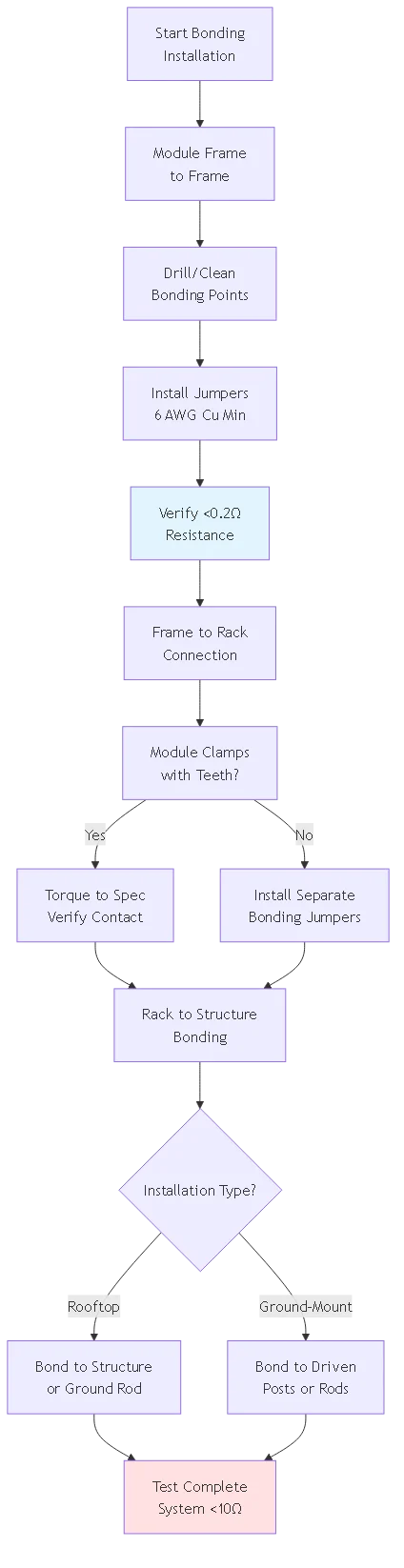
Die Verklebung verbindet alle metallischen PV-Komponenten, um ein Äquipotenzial zu schaffen, das Spannungsunterschiede zwischen den Komponenten bei Blitzeinschlägen verhindert. Ungeklebte Rahmen können im Vergleich zu geerdeten Geräten ein Potenzial von 50.000 V+ entwickeln.
Zweck: Stellen Sie die elektrische Kontinuität über die gesamte Anordnung her. Jeder Modulrahmen muss mit den benachbarten Rahmen mit gemessenem Widerstand verbunden sein <0,2Ω zwischen zwei beliebigen Punkten.Spezifikation des Bonding-Jumpers:
- Mindestgröße: 6 AWG Kupfer, 4 AWG Aluminium
- Typ: Verseilt für Flexibilität (thermische Ausdehnung/Kontraktion)
- Isolierung: THWN-2 oder blankes Kupfer (wenn vor mechanischer Beschädigung geschützt)
- Länge: ≤18 Zoll halten, um die Induktivität zu minimieren
Einbauverfahren:
Schritt 1: Identifizierung von Verbindungspunkten
Die Modulrahmen verfügen in der Regel über werkseitig gebohrte Verbindungslöcher. Falls nicht vorhanden, verwenden Sie selbstbohrende/schneidende Schrauben mit einer Sternscheibe, die die Eloxierung oder Beschichtung durchdringt. Verlassen Sie sich niemals auf den Reibungskontakt zwischen lackierten/eloxierten Oberflächen - isolierende Beschichtungen verhindern den elektrischen Durchgang.
Schritt 2: Klebelaschen vorbereiten
1/2 Zoll Isolierung von den Enden der Klebebrücke abisolieren. In die für die Leitergröße ausgelegte Presslasche einführen. Crimpen Sie mit einer Sechskant-Crimpzange (nicht mit einer Zange - zu wenig Druck). Zwei-Loch-Kabelschuhe bieten eine redundante mechanische Verbindung.
Schritt 3: Befestigung am Modulrahmen
Positionieren Sie die Lasche gegen den Rahmen am Klebeloch. Stecken Sie die Edelstahlschraube (3/8″ oder 1/4″ Durchmesser) durch das Loch der Lasche und das Loch im Rahmen. Sternförmige Unterlegscheibe unter den Schraubenkopf legen - die scharfen Zähne beißen sich durch die Beschichtung und stellen den Metall-Metall-Kontakt her. Mit einem Drehmoment von 7-9 N⋅m (60-80 in-lbs) anziehen. Tragen Sie vor der Montage in küstennahen/industriellen Umgebungen ein Antioxidationsmittel auf.
Schritt 4: Überprüfen der Kontinuität
Verwenden Sie ein Digitalmultimeter (DMM), um den Widerstand zwischen entfernten Rahmen zu messen. Ein Wert von >0,2Ω deutet auf eine schlechte Verbindung hin - demontieren, Oberflächen reinigen und wieder montieren. Häufige Ursachen: lackierte Oberflächen nicht durchdrungen, fehlende Sternscheibe, unzureichendes Drehmoment.
Die Gestelle bilden den Hauptstrompfad zu den Erdungselektroden. Die Modulrahmen müssen mit den Regalschienen verbunden werden und dieselben Anforderungen an die Widerstandsfähigkeit erfüllen.
Methoden der Verklebung:
Methode 1: Modulklemmen mit Klebezähnen
Viele moderne Klemmen haben gezackte Zähne, die beim Anziehen in den Modulrahmen und die Schiene eindringen. Stellen Sie sicher, dass die Zähne das unlackierte Metall auf beiden Seiten berühren. Ziehen Sie die Klemmen gemäß den Herstellerangaben an und stellen Sie sicher, dass die Zähne vollständig in das Metall eindringen.
Methode 2: Getrennte Steckbrücken für die Verbindung
Wenn die Klemmen nicht geklebt werden können, müssen entsprechende Steckbrücken installiert werden:
- Verbindung vom Klebepunkt des Modulrahmens zum Klebeloch der Schiene
- Verwenden Sie dieselbe Methode für Laschen/Schrauben/Scheiben wie bei der Verklebung von Rahmen zu Rahmen.
- Installieren Sie einen Jumper pro Modul oder jedes zweite Modul (der Systementwickler legt dies anhand von Fehlerstromberechnungen fest)
Methode 3: Werksgeklebte Systeme
Einige Regalsysteme verfügen über ein integriertes Klebemodul, dessen Gewicht auf speziellen Klemmen die Klebeverbindung herstellt. Hierfür ist eine Herstellerzertifizierung erforderlich, die Widerstandsmessungen dokumentiert. Eine Überprüfung vor Ort ist nach wie vor erforderlich - trauen Sie Marketingaussagen nicht ohne Daten.
Letzter Link: Das Regalsystem muss mit der Gebäudestruktur (Dach) oder den Erdungselektroden (Erdmontage) verbunden sein. Damit ist der Weg vom Blitzeinschlag (der durch den Luftabschluss aufgefangen wird) über die Modulrahmen und die Gestelle zur Erde abgeschlossen.
Aufdachanlagen:
Verlegen Sie den Potentialausgleichsleiter vom primären Regalbefestigungspunkt bis:
- Baustahl (wenn elektrisch durchgängig und geerdet)
- Spezielle Erdungselektrode auf dem Dach (wenn die Struktur nicht leitend ist)
- Ableitungsanschlusspunkt für Blitzschutzsystem
Verwenden Sie mindestens 2 AWG als Verbindungsleiter. In gerader Linie verlegen und scharfe Biegungen vermeiden. Schützen Sie das Kabel vor mechanischer Beschädigung in begangenen Bereichen.
Bodenmontierte Installationen:
In die Erde getriebene Regalpfosten bieten eine natürliche Erdung:
- Das Pfostenmaterial ist leitfähig (Stahl, nicht Glasfaser)
- Pfosten ragen mehr als einen Meter in den Boden und berühren die Erde
- Der Bodenwiderstand ist angemessen (<500 Ω⋅m)
Überprüfen Sie dies mit einer Widerstandsmessung. Wenn die Pfosten allein nicht ausreichen <10Ω, zusätzliche Erdungsstangen am Umfang installieren und mit dem Gestell verbinden.
Anlagen mit mehr als 50 kW profitieren von einem Erdungsring (auch Erdungsschleife genannt) - einem vergrabenen Leiter, der den Umfang der Anlage umgibt. Dies bietet mehrere Erdungspunkte und reduziert die Erdungsimpedanz.
Konzept: Anstelle von diskreten Punktkontakten (Erdungsstäben) bietet der Ringleiter einen kontinuierlichen Erdungskontakt um den gesamten Array-Perimeter. Die Gesamtkontaktfläche ist weitaus größer als bei einzelnen Stäben, was den Widerstand drastisch reduziert.
Effektivität: Ein ordnungsgemäß installierter Erdungsring erreicht unter den meisten Bodenbedingungen einen Widerstand von 3-6Ω - ohne zusätzliche Stäbe ein Zielwert von unter 10Ω. Schlechte Böden erfordern möglicherweise eine Verstärkung mit chemischen Erdungsstäben oder Bentonitbehandlung.
Mindestgröße2 AWG Kupfer oder 1/0 AWG Aluminium blanker Leiter.
Materielle Gegenleistung: Blankes Kupfer ist in den meisten Böden korrosionsbeständig. Einige korrosive Umgebungen (hoher Schwefelgehalt, industrielle Verschmutzung) erfordern verzinntes Kupfer oder Aluminium mit Korrosionsschutzbeschichtung.
Physikalische Eigenschaften: Litzenleiter passen sich den Unebenheiten des Grabens besser an als massive Leiter. Die Flexibilität gleicht unterschiedliche Setzungen und Wärmeausdehnungen aus.
Schritt 1: Grundriss und Aushub
Markieren Sie den Ringumfang 3-6 Fuß außerhalb der Grundfläche des Arrays. Dieser Abstand stellt sicher, dass der Ring über den “Schatten” der Struktur hinausreicht und Zugang zu ungestörtem Boden hat. Graben 18-30 Zoll tief und 6 Zoll breit ausheben. Tieferes Eingraben ermöglicht den Zugang zu feuchten Bodenschichten und schützt den Leiter vor Frostbeulen.
Schritt 2: Vorbereitung des Grabens
Entfernen Sie Steine >2 Zoll von der Grabensohle - Steine schaffen Luftspalten, die den Erdkontakt verringern. Wenn der Boden trocken ist (Widerstand >200 Ω⋅m), ist eine Anreicherung in Betracht zu ziehen:
- Auskleidung des Grabens mit Bentonit-Ton (quillt bei Nässe auf, hält die Feuchtigkeit)
- Einbau von leitfähigem Beton (spezielle Mischung mit gemahlenem Kohlenstoff)
- Verwendung von chemischen Erdungsstäben in Abständen von 20 Fuß entlang des Rings
Schritt 3: Installation des Leiters
Rollen Sie die Leitung in den Graben ab und vermeiden Sie dabei Knicke oder scharfe Biegungen. Stützen Sie den Leiter auf einer 2-Zoll-Schicht aus feinem Boden (keine Steine). Halten Sie an Ecken einen Mindestradius von 8 Zoll ein - scharfe Ecken erhöhen die Impedanz. Wenn die Leitung unter Gehwegen oder Straßen verlaufen muss, ist sie zum mechanischen Schutz mit einem PVC-Rohr zu ummanteln.
Schritt 4: Anschlüsse für den Erdungsstab
Installieren Sie Erdungsstangen an Ringecken und in der Mitte von langen Strecken (≤50 Fuß Abstand). Verbinden Sie die Stangen mit dem Ringleiter durch exothermes Schweißen oder mit einer Pressklemme. Diese Stangen ergänzen den Ring, bieten Redundanz und senken den Gesamtwiderstand.
Schritt 5: Kleben von Leiterbefestigungen
Bringen Sie die Verbindungsleiter vom Array-Rack zum Ring an mehreren Punkten an (mindestens 4 für Arrays). <100kW, zusätzliche Punkte alle 30m des Umfangs für größere Arrays). Verbinden mit: - Exotherme Schweißung (optimal-homogene Verbindung) - Irreversible Kompressionsverbindungen (gut-mechanische Kaltverschweißung) - Geschraubte Spaltbolzenverbindungen mit Antioxidationsmittel (akzeptabel - regelmäßige Inspektion erforderlich)
Schritt 6: Prüfung vor der Verfüllung
Entscheidend: Testen Sie den Ringwiderstand VOR der Verfüllung. Die Korrektur von Widerstandsproblemen nach dem Eingraben erfordert Aushub. Verwenden Sie ein Erdungsprüfgerät mit Klemme oder die Potentialabfallmethode. Ziel: <8Ω für den Ring allein, <6Ω nach Pleuelstangen.
Schritt 7: Aufschüttung und Verdichtung
Bedecken Sie den Leiter mit 6 Zoll feiner Erde (durch Sieben werden Steine >1/2 Zoll entfernt). Dadurch entsteht ein enger Kontakt zwischen Leiter und Erde. Verdichten Sie die Erde nur leicht - belasten Sie den Leiter nicht. Bringen Sie 6 Zoll unter dem endgültigen Niveau ein Warnband an, das die Lage der vergrabenen Leitung markiert. Verfüllen Sie den Boden bis zum ursprünglichen Niveau und verdichten Sie ihn in mehreren Schichten, um Setzungen zu verhindern.
⚠️ Wichtig: Dokumentieren Sie die Position des Rings mit GPS-Koordinaten und Verlegetiefe. Jahre später werden diese Informationen bei Ausgrabungen für Reparaturen oder Erweiterungen benötigt, um eine Beschädigung des Erdungssystems zu vermeiden.
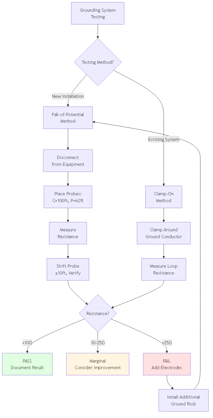
Die Qualität der Installation bestimmt die Wirksamkeit der Erdung. Eine ordnungsgemäße Prüfung verifiziert, dass das fertige System die Widerstandsziele und die NEC/NFPA-Anforderungen erfüllt.
Die genaueste Feldmethode zur Messung des Erdungswiderstands. Erfordert ein spezielles Erdungsprüfgerät (Megger, Fluke oder gleichwertig).
Einrichtung der Ausrüstung:
- Erdungsprüfgerät mit drei Klemmen (X, P, C)
- Zwei Prüfsonden (Stromsonde und Potenzialsonde)
- 200 Fuß Testkabel
- Hammer für Fahrprüfungssonden
Verfahren:
Schritt 1: Erdungsanlage abtrennen
Trennen Sie das Erdungselektrodensystem vorübergehend von der PV-Anlage. Dadurch wird das zu prüfende System von parallelen Pfaden isoliert, die zu falschen niedrigen Messwerten führen würden.
Schritt 2: Platzierung der Sonde
Führen Sie die Stromsonde (C) 100 Fuß von der Erdungselektrode in gerader Linie. Führen Sie die Potentialsonde (P) im Abstand von 62% (62 Fuß von der Elektrode, 38 Fuß von der Stromsonde). Dieser Abstand von 62% eliminiert gegenseitige Kopplungseffekte zwischen Elektrode und Sonden.
Schritt 3: Testgerät anschließen
Klemme X des Testers mit der Erdungselektrode verbinden. Klemme P an die Potentialsonde anschließen. Klemme C an die Stromsonde anschließen. Stellen Sie sicher, dass die Anschlüsse dicht sind - der Widerstand in den Messleitungen verfälscht die Messwerte.
Schritt 4: Messung durchführen
Aktivieren Sie das Prüfgerät. Moderne Geräte leiten Prüfstrom ein und messen die daraus resultierende Spannung, wobei der Widerstand automatisch berechnet wird. Der Messwert sollte sich innerhalb von 10-20 Sekunden stabilisieren. Ergebnis aufzeichnen.
Schritt 5: Überprüfen Sie die Verschiebung der Sondenposition
Bewegen Sie die Potentialsonde 10% näher heran (bis zur Position 52%) und messen Sie erneut. Bewegen Sie dann 10% weiter (bis zur Position 72%) und messen Sie erneut. Die drei Messwerte sollten innerhalb von 10% übereinstimmen. Ist dies nicht der Fall, ist die aktuelle Sonde zu nahe dran - verlängern Sie auf 150 Fuß und wiederholen Sie die Messung.
Schritt 6: Interpretation der Ergebnisse
- <5Ω: Excellent grounding - 5-10Ω: Acceptable for most applications - 10-25Ω: Marginal—meets NEC minimum but consider improvements - >25Ω: Unzureichend - zusätzliche Elektroden erforderlich
Schnellere Methode für installierte Systeme, bei denen die Prüfung des Potenzialabfalls nicht praktikabel ist (das System kann nicht abgeschaltet werden, begrenzter Platz verhindert die Platzierung der Sonde).
Begrenzung: Erfordert eine geschlossene Schleife im Erdungssystem (Erdungsring oder mehrere verbundene Stäbe). Funktioniert nicht bei einem einzelnen isolierten Erdungsstab.
Verfahren:
Klemmenprüfgerät um den Erdungsleiter legen. Das Prüfgerät speist ein Signal in den Leiter ein und misst den Schleifenwiderstand. Das Ergebnis kommt dem tatsächlichen Erdungswiderstand nahe, wenn das System mehrere parallele Pfade zur Erde hat. Weniger genau als der Potenzialabfall, aber nützlich für die schnelle Überprüfung vor Ort und die regelmäßige Überwachung.
Erstinstallation: Prüfung vor der Einschaltung und vor dem Vergraben der Leiter. Dokumentieren Sie den Grundlinienwiderstand.
Jährliche Prüfung: Jährlich bei der Wartung erneut testen. Vergleich mit dem Ausgangswert - ein Anstieg >20% deutet auf eine Verschlechterung hin (Korrosion, lose Verbindungen, Änderungen der Bodenfeuchtigkeit).
Nach dem Blitzeinschlag: Testen Sie immer nach bekannten Blitzeinschlägen. Der Einschlagstrom kann Verbindungen verdampfen oder Elektroden beschädigen. Eine verschlechterte Erdung schützt nicht vor dem nächsten Einschlag.
Nach der Bodenstörung: Durch Bauarbeiten, Landschaftsgestaltung oder Erosion in der Nähe des Erdungssystems wird der Bodenkontakt verändert. Test verifiziert, dass die Integrität erhalten bleibt.
| Widerstandsbereich | Leistung | Erforderliche Maßnahmen |
|---|---|---|
| <5Ω | Ausgezeichnet | Keine-erfüllt alle Standards |
| 5-10Ω | Gut | Zulässiges Dokument |
| 10-15Ω | Marginal | Erfüllt NEC-Mindestanforderungen, Monitor |
| 15-25Ω | Schlecht | Hinzufügen zusätzlicher Elektroden |
| >25Ω | Unzureichend | Nachbesserung erforderlich - Inspektion nicht bestanden |
Problem: Installation von 6-Fuß-Erdungsstäben anstelle der gesetzlich vorgeschriebenen 8-Fuß-Mindestlänge oder Abbruch, wenn der Stab auf eine flache Felsschicht trifft. Eine unzureichende Tiefe verringert die Erdkontaktfläche und erhöht den Widerstand.
Allgemeine Szenarien:
- Verwendung von 6-Fuß-Stangen aus dem Wohnbereich für gewerbliche Installationen
- Angelrute beim Auftreffen auf einen Felsen, anstatt sich zu verlagern
- Zählen der Stange über dem Boden als Erfüllung der Tiefenanforderung
Berichtigung: Verwenden Sie mindestens 8 Fuß lange Stangen, in trockenen Böden vorzugsweise 10 Fuß lange. Wenn Felsen die volle Tiefe verhindern, verlegen Sie die Stangen oder installieren Sie mehrere kürzere Stangen parallel. Neigen Sie die Ruten niemals um mehr als 15° von der Senkrechten ab - dies verringert die Wirksamkeit erheblich.
Problem: Verlassen auf Reibungskontakt zwischen lackierten/eloxierten Oberflächen, fehlende Sternscheiben oder unzureichendes Drehmoment. Dies führt zu hochohmigen Verbindungen, die bei Blitzeinschlag einen Lichtbogen erzeugen.
Allgemeine Szenarien:
- Verschraubung von Laschen an lackierten Modulrahmen ohne durchdringende Beschichtung
- Verwendung von Unterlegscheiben anstelle von Sternscheiben
- Handfestes Anziehen statt Anziehen nach Spezifikation
- Keine antioxidative Verbindung in korrosiven Umgebungen
Berichtigung: Verwenden Sie Sternscheiben an jeder Klebeverbindung. Anziehen mit 7-9 N⋅m für Modulrahmenverbindungen, 15-20 N⋅m für Erdungsstabklemmen. Tragen Sie auf alle Kupfer-Aluminium- und Außenanschlüsse ein Antioxidationsmittel auf.
Problem: Durch direkten Kontakt zwischen Kupfer und Aluminium entsteht eine galvanische Zelle, die die Verbindung korrodiert und den Widerstand erhöht. Tritt bei Verbindungsbrücken, Kabelschuhen und Erdungsklemmen auf.
Allgemeine Szenarien:
- Kupfer-Bonding-Leiter in Aluminiumklemme
- Aluminium-Modulrahmen mit Kupferfahne verklebt (keine Barriere)
- Stahlbolzen zur Verbindung von Kupferbauteilen
Berichtigung: Verwenden Sie kompatible Metalle (Kupfer-Kupfer, Aluminium-Aluminium) oder zugelassene Bimetallverbindungen. Tragen Sie ein Antioxidationsmittel auf, das für Verbindungen aus unterschiedlichen Metallen geeignet ist. Verwenden Sie Verbindungselemente aus rostfreiem Stahl, die sowohl für Kupfer als auch für Aluminium neutral sind.
Problem90° oder schärfere Biegungen erhöhen die Impedanz bei Blitzfrequenzen drastisch. Der Hochfrequenzstrom konzentriert sich an den Biegungen und erzeugt heiße Stellen, die den Leiter schmelzen können.
Allgemeine Szenarien:
- Rechtwinklige Kurven an Gebäudeecken
- Enge Kurven um Hindernisse
- Schleifen von überschüssigen Leitern anstelle von Abschneiden
Berichtigung: Halten Sie bei allen Kurven einen Mindestradius von 8 Zoll ein. Verwenden Sie allmähliche, geschwungene Kurven anstelle von scharfen Winkeln. Wenn der Platz begrenzt ist, verwenden Sie zwei 45°-Kurven anstelle einer einzigen 90°-Kurve.
Problem: Die direkte Verbindung der Blitzschutzerde mit der Erdung des Stromnetzes ohne ordnungsgemäße Isolierung führt bei Gewittern zu zirkulierenden Strömen, die empfindliche elektronische Geräte beschädigen können.
Allgemeine Szenarien:
- Anschluss des Ableiters an den Erdungsstab des Hausanschlusses
- Nutzung der Ufererde als Blitzschutz für das Gebäudefundament
- Ein einziger Erdungsstab für Blitzschutz- und elektrische Systeme
Berichtigung: Installieren Sie ein separates Blitzschutz-Erdungssystem gemäß NFPA 780. Verbinden Sie die beiden Systeme mit mindestens 6 AWG-Leitern, aber halten Sie einen räumlichen Abstand (mehr als 10 Fuß) zwischen den Elektroden ein. Dies ermöglicht einen Potenzialausgleich und verhindert gleichzeitig zirkulierende Ströme im elektrischen System.
Wenn die Prüfung ergibt, dass der Widerstand über den Zielwerten liegt, werden bei der systematischen Fehlersuche die Ursachen und Lösungen ermittelt.
Einzelne Elektroden testen: Wenn mehrere parallel geschaltete Stäbe einen hohen Gesamtwiderstand aufweisen, testen Sie jeden Stab einzeln. Dadurch wird festgestellt, ob alle Stäbe einen hohen Widerstand aufweisen (Bodenproblem) oder ob ein Stab schlecht angeschlossen ist (Installationsproblem).
Verbindungen prüfen: Ein Widerstand von >25Ω bei ordnungsgemäß angebrachten Elektroden weist in der Regel auf Verbindungsprobleme hin. Demontieren Sie jede Klemme/Fahne, reinigen Sie die Oberflächen mit einer Drahtbürste, tragen Sie ein Antioxidationsmittel auf und montieren Sie sie wieder mit dem richtigen Drehmoment.
Überprüfen der Elektrodentiefe: Bestätigen Sie, dass die Ruten eine volle Tiefe von mehr als einem Meter erreichen. Flache Ruten in trockenen Oberflächenböden haben einen 2-5-fach höheren Widerstand als tiefe Ruten in feuchten Substraten.
Bewertung der Bodenverhältnisse: Die jüngste Trockenheit erhöht den Bodenwiderstand drastisch. Nasser Boden nach Regen führt zu irreführend niedrigen Messwerten. Testen Sie bei typischen Feuchtigkeitsbedingungen, nicht bei extremer Nässe/Trockenheit.
Parallele Erdungsstangen hinzufügen: Die effektivste Lösung. Jeder zusätzliche Stab in Parallelschaltung verringert den Gesamtwiderstand. Abstand zwischen den Stäben ≥2× Stablänge für Unabhängigkeit. Vier Stäbe erreichen in der Regel <10Ω in allen außer den schlechtesten Böden.Tiefe der Stange erhöhen: Wenn sich der Boden in der Tiefe verbessert (Felsen an der Oberfläche, feuchter Lehm darunter), treiben Sie längere Stangen ein (10-12 Fuß) oder verwenden Sie Bohrlöcher mit Aufschüttung. Einige kommerzielle Systeme verwenden 20 Fuß tief getriebene Elektroden.
Erdungsring einbauen: Bei großen Anlagen, bei denen mehrere Stangen nicht ausreichen, bietet der Erdungsring einen umfassenden Erdkontakt. Der Ring allein erreicht oft 3-6Ω in mäßigem Boden.
Chemische Behandlung: Letzter Ausweg für wirklich schlechte Böden (fester Fels, sehr trockener Sand). Optionen:
- Bentonit-Tonverfüllung um die Stäbe (absorbiert Feuchtigkeit, erhält die Leitfähigkeit)
- Leitfähiger Beton (spezielle Mischung mit Kohlenstoffzusätzen)
- Chemische Erdungsstäbe (hohle Stäbe, die mit elektrolytischen Salzen gefüllt sind, die in den Boden sickern)
Kostenüberlegungen: Die Installation von zwei zusätzlichen Erdungsstäben kostet $100-200. Chemische Behandlungen kosten $500-1500 pro Elektrode. Planung für geeignete Elektroden bei der Erstinstallation - Nachrüstung kostet 3-5x mehr als eine korrekte Erstinstallation.
Eine ordnungsgemäße Dokumentation beweist die Einhaltung des Codes und bildet die Grundlage für die Wartung während der gesamten Lebensdauer des Systems.
Zeichnungen für Erdungssysteme: Bestandspläne, die zeigen:
- Standorte von Erdungsstangen mit GPS-Koordinaten
- Erdungsringleitung (falls vorhanden)
- Bonding von Leiterbahnen
- Standorte der Anschlussstellen
- Tiefen und Abstände der Elektroden
Prüfberichte: Dokument einschließlich:
- Verwendete Prüfmethode (Potentialabfall, Clamp-On)
- Einzelne Elektrodenwiderstände
- Kombinierter Systemwiderstand
- Testdatum und Wetterbedingungen
- Modell des Prüfgeräts und Datum der Kalibrierung
Zertifizierungen von Materialien: Auflistung der Dokumentation für:
- Erdungsstangen (UL 467)
- Potentialausgleichsleiter (UL 854)
- Klemmen und Laschen (UL 467)
- Anti-Oxidationsmittel (UL-Liste)
Fotos der Installation: Visuelle Aufzeichnung von:
- Rammen von Erdstäben (Anzeige der erreichten Tiefe)
- Verbindungen vor der Beerdigung verbinden
- Einbau des Erdungsrings im Graben
- Fertiggestelltes System
Die meisten Gerichtsbarkeiten verlangen eine Inspektion des Erdungssystems vor der Einschaltung. Der Inspektor prüft:
- Die Tiefe der Erdungsstange entspricht NEC 250.53(G) (mindestens 8 Fuß)
- Die Leiterdimensionierung entspricht den Mindestanforderungen des NEC 690.43
- Die Klebeverbindungen haben Sternscheiben und das richtige Drehmoment
- Der Erdungswiderstand entspricht NEC 250.56 (<25Ω) und vorzugsweise NFPA 780 (<10Ω)
Zeitpunkt der Inspektion: Beantragen Sie eine Inspektion nach der Installation der Erdung, aber VOR der Verfüllung der Leitungen. Der Inspektor muss die vergrabenen Arbeiten vor der Abdeckung sehen. Planen Sie die Inspektion vor dem Gießen von Beton oder der endgültigen Planierung.
Erdungsstangen müssen gemäß NEC 250.53(G) mindestens 8 Fuß tief getrieben werden, wobei die Oberkante der Stange 2 bis 4 Zoll unter dem endgültigen Niveau liegen muss. Diese Tiefe stellt sicher, dass die Elektroden unter die Frostgrenze reichen und Zugang zu feuchten Bodenschichten haben, die einen geringeren Widerstand aufweisen. In trockenem oder felsigem Boden bieten 10-Fuß-Stäbe eine bessere Leistung - die zusätzliche Tiefe von 25% reduziert den Widerstand oft um 30-40% im Vergleich zu 8-Fuß-Stäben. Wenn das Gestein das Einsetzen in voller Tiefe verhindert, erlaubt die NEC eine zusätzliche seitliche Erdungselektrode innerhalb von 6 Zoll vom Stab, aber dies ist weniger effektiv als die richtige Tiefe. Alternativ können Sie den Stab an eine Stelle im Boden verlegen, die die volle Tiefe zulässt, oder mehrere Stäbe parallel installieren. Schneiden Sie die Stäbe niemals kürzer als 8 Fuß - dies verstößt gegen die Vorschriften und verringert die Wirksamkeit der Erdung erheblich. In Küstengebieten und Gebieten mit hohem Blitzschlag sollte ein Mindestabstand von 10 Fuß eingehalten werden, um den Schutz zu erhöhen. Dokumentieren Sie die tatsächliche Tiefe, die für jeden Stab erreicht wurde, in den Bestandsplänen - Inspektoren überprüfen häufig die Einhaltung der Vorschriften, und diese Informationen sind für die künftige Wartung oder Erweiterung des Systems wichtig.
Blitzschutz-Erdungsleiter müssen gemäß den NFPA 780-Normen mindestens 2 AWG Kupfer oder 1/0 AWG Aluminium aufweisen - wesentlich größer als die Mindestanforderungen für die elektrische Erdung nach NEC. Diese Dimensionierung spiegelt die unterschiedlichen Anforderungen wider: Bei einem Blitzschlag treten massive transiente Ströme bei hohen Frequenzen auf, die eine niedrige Induktivität erfordern, während die elektrische Erdung stationäre Fehlerströme bewältigt, bei denen die Strombelastbarkeit die Größe bestimmt. Für eine kombinierte Blitzschutz-/Erdung (häufig bei PV-Anlagen) sind Leiter zu verwenden, die die höheren Blitzschutzanforderungen erfüllen: Mindestens 2 AWG Kupfer für Wohngebäude (<10kW), 1/0 AWG for commercial (10-100kW), and 2/0 AWG for utility systems (>100kW). Litzenleiter sind wegen der geringeren AC-Impedanz und der besseren Flexibilität den Massivleitern vorzuziehen. Modulrahmen-Verbindungsbrücken können kleiner sein - mindestens 6 AWG Kupfer - aber Hauptableitungen und Erdungselektrodenleiter erfordern die volle blitzstromtaugliche Dimensionierung. Im Zweifelsfall sollte die Größe erhöht werden - der Kostenunterschied zwischen 2 AWG und 1/0 AWG beträgt $1-2 pro Fuß, bietet aber eine erhebliche Sicherheitsmarge.
Die Erdung des elektrischen Systems und die Blitzschutzerdung sollten getrennte Systeme sein, die miteinander verbunden sind, und nicht dasselbe System. Die elektrische Erdung nach NEC 250 ist für 60 Hz-Wechselstromfehlerströme in Amperehöhe optimiert, wobei kleinere Leiter und ein einziger Erdungsstab oft ausreichen. Der Blitzschutz nach NFPA 780 ist für Mikrosekundentransienten mit 20.000-200.000 Ampere ausgelegt und erfordert größere Leiter und mehrere Elektroden. Der Versuch, die Erdung des Stromnetzes für den Blitzschutz zu verwenden, birgt folgende Risiken: unzureichende Größe der Leiter, die bei einem Blitzeinschlag verdampft, eine einzelne Elektrode, die die Blitzenergie nicht ableiten kann (Spannungsanstieg führt zu Schäden an den Geräten), und zirkulierende Ströme im elektrischen System, die empfindliche Elektronik beschädigen. Der richtige Ansatz: Installieren Sie ein spezielles Blitzschutz-Erdungssystem mit mehreren Elektroden und großen Leitern und verbinden Sie es dann mit der Erdung der elektrischen Anlage mit einem Leiter von mindestens 6 AWG. Dadurch wird der Potenzialausgleich aufrechterhalten (Vermeidung von Lichtbögen zwischen den Systemen), während der Blitzstrom hauptsächlich in den Blitzschutzleitern und nicht in den elektrischen Leitungen fließt. Die räumliche Trennung der Elektroden (mehr als 10 Fuß) verhindert, dass sich die Widerstandskugeln überlappen, während die Verbindung die Spannung ausgleicht.
Prüfen Sie den Widerstand des Erdungssystems mindestens einmal jährlich, vorzugsweise während der saisonalen Wartungsarbeiten, wenn die Wetterbedingungen der Betriebsumgebung des Systems entsprechen (nicht unmittelbar nach Regen, der fälschlicherweise niedrige Messwerte ergibt). Der erste Basistest während der Inbetriebnahme dient als Referenz für den Vergleich - ein Anstieg des Widerstands um mehr als 20% gegenüber dem Basistest weist auf eine Verschlechterung hin, die untersucht werden muss. Zusätzliche Tests sind erforderlich: nach bekannten Blitzeinschlägen (der Strom kann Verbindungen beschädigen oder Leiterabschnitte verdampfen), nach Bau- oder Landschaftsarbeiten, die das Erdreich in der Nähe der Erdungselektroden beeinträchtigen (Änderung der Bodenverdichtung und -feuchtigkeit), und wenn Überwachungssysteme anormale Erdschlussereignisse anzeigen (kann auf eine beeinträchtigte Erdung hinweisen). Gewerbliche Anlagen und Anlagen im Versorgungsbereich sollten aufgrund der höheren Blitzeinwirkung und des größeren Wertes der gefährdeten Geräte halbjährlich geprüft werden. Die Kosten für die Prüfung betragen $200-500 für einen professionellen Service für private Anlagen, $500-1500 für gewerbliche Anlagen - ein geringer Preis im Vergleich zum Austausch der Anlage nach einem Blitzschaden. Dokumentieren Sie alle Prüfergebnisse unter Angabe des Datums, der angewandten Methode, der Wetterbedingungen und der einzelnen Elektrodenmessungen, wenn Sie parallele Stangensysteme prüfen. Viele Versicherungspolicen verlangen eine dokumentierte jährliche Prüfung, um den Versicherungsschutz aufrechtzuerhalten.
Ein hoher Bodenwiderstand (>10-25Ω) hat in der Regel vier Ursachen. Erstens, unzureichende Elektrodentiefe - Stangen, die feuchte Bodenschichten nicht erreichen, sorgen für schlechten Erdkontakt. Lösung: treiben Sie die Stangen bis zur vollen Tiefe von 8-10 Fuß ein oder installieren Sie tiefere Elektroden, wenn der flache Untergrund eine Standardtiefe verhindert. Zweitens: Schlechte Leitfähigkeit des Bodens - trockener Sandboden, Kies oder fester Fels haben einen spezifischen Widerstand von 500-10.000 Ω⋅m gegenüber 50-200 Ω⋅m bei normalem Boden. Lösung: Installieren Sie mehrere parallele Erdungsstangen im Abstand von 2× Stangenlänge oder fügen Sie einen Erdungsring um die Anlage herum hinzu. Drittens: Fehlerhafte Verbindungen - korrodierte Klemmen, fehlende Unterlegscheiben oder unzureichendes Drehmoment führen zu hohem Widerstand an den Verbindungspunkten. Lösung: Demontieren Sie alle Verbindungen, reinigen Sie sie mit einer Drahtbürste, tragen Sie ein Antioxidationsmittel auf und ziehen Sie sie mit dem richtigen Drehmoment wieder an. Viertens: Jahreszeitlich bedingte Schwankungen der Bodenfeuchtigkeit - der Widerstand verdoppelt oder verdreifacht sich bei Trockenheit, wenn der Boden austrocknet. Lösung: Testen Sie unter typischen Feuchtigkeitsbedingungen und planen Sie das System mit Spielraum. Bei anhaltend hohem Widerstand trotz dieser Abhilfemaßnahmen ist eine chemische Verstärkung in Betracht zu ziehen: Bentonitton um die Stäbe herum hält die Feuchtigkeit aufrecht ($50-100 pro Stab), oder chemische Erdstäbe geben elektrolytische Salze in den Boden ab ($200-400 pro Elektrode). Mehrere parallel geschaltete Stäbe sind in den meisten Fällen die kostengünstigste Lösung.
Ja und nein - es sollte sich um getrennte Systeme mit unabhängigen Elektroden handeln, die jedoch an einem Punkt miteinander verbunden sind. Nach NEC 250.50 müssen alle Erdungselektroden eines Gebäudes miteinander verbunden sein, um gefährliche Spannungsunterschiede zwischen den Systemen bei elektrischen Ereignissen zu verhindern. Der Blitzschutz nach NFPA 780 erfordert jedoch eigene Elektroden und Leiter, die für Blitzströme und nicht für elektrische Fehlerströme ausgelegt sind. Korrekte Umsetzung: Installieren Sie Blitzschutz-Erdungsstangen an den durch die Luftabschlusskonstruktion berechneten Stellen (typischerweise an Gebäudeecken und am Feldrand) und verwenden Sie Leiter mit mindestens 2 AWG. Installieren Sie eine separate elektrische Systemerdung gemäß NEC Artikel 250 am Hausanschluss. Verbinden Sie dann die beiden Systeme mit 6 AWG-Kupferbrücken, aber halten Sie einen Abstand von mehr als einem Meter zwischen den Elektrodengruppen ein. Diese Trennung verhindert, dass der Blitzstrom durch die Leiter der elektrischen Anlage fließt (die dafür nicht ausgelegt sind), während die Verbindung die Spannung ausgleicht und zerstörerische Lichtbögen zwischen den Systemen verhindert. Manche Installateure versuchen, mit einer einzigen gemeinsamen Erdung Geld zu sparen - dies verstößt gegen NFPA 780, führt zu Problemen bei der Einhaltung von Vorschriften und birgt die Gefahr, dass Geräte durch zirkulierende Ströme beschädigt werden. Eine ordnungsgemäße Trennung mit Erdung kostet $100-300 mehr, bietet aber den richtigen Schutz und die Genehmigung des Inspektors.
Ein Erdpotentialanstieg (GPR) tritt auf, wenn ein großer Strom in eine begrenzte Erdverbindung fließt und die örtliche Erdspannung über den entfernten Erdbezugspunkt anhebt. Bei einem Blitzeinschlag fließen 100.000 Ampere in eine 10-Ω-Erdungselektrode, was zu einem sofortigen Anstieg des örtlichen Erdpotentials um 1.000.000 Volt (1MV) führt. Dies ist insofern von Bedeutung, als Geräte, die an dieses Erdungssystem angeschlossen sind, auf diese Spannung im Verhältnis zur entfernten Erde ansteigen, während andere Systeme auf echter Erde bleiben. Spannungsunterschiede zwischen den Systemen verursachen Lichtbögen, die die Elektronik zerstören und zu Stromschlägen führen können. Beispiel: Ein Blitz schlägt in eine Anlage ein, der Strom fließt zur Erdungselektrode und erzeugt 50.000 V GPR. Das elektrische System des Gebäudes in 100 Fuß Entfernung bleibt auf echter Erdung (0 V). Die Spannungsdifferenz schlägt Lichtbögen durch den Wechselrichter, der an beide Systeme angeschlossen ist, und zerstört ihn. Zur Vorbeugung sind folgende Maßnahmen erforderlich: ein niedriger Erdungswiderstand, der den Spannungsanstieg verringert (ein 5Ω-Widerstand führt zu 500.000 V im Vergleich zu 1 MV - immer noch hoch, aber von kürzerer Dauer), mehrere verteilte Elektroden, die den Strom verteilen (verringert den Spannungsanstieg pro Elektrode), und die Verbindung aller Systeme untereinander (gleicht die Spannung aus - kein Lichtbogen, selbst wenn alle Systeme zusammen ansteigen). Aus diesem Grund ist ein Erdungsring einem einzelnen Erdungsstab für den Blitzschutz überlegen - ein verteilter Kontakt verringert den Anstieg der Spitzenspannung bei einem Blitzeinschlag. GPR erzeugt auch gefährliche Stufenpotentiale in der Nähe von Erdungselektroden - das Personal sollte bei Gewitter Bereiche im Umkreis von 10 Fuß von Erdungsstäben meiden.
Eine ordnungsgemäße Blitzschutzerdung für Solaranlagen erfordert ein Verständnis für grundlegend andere Anforderungen als die Erdung von elektrischen Anlagen. Die massiven transienten Ströme, die Anstiegszeiten im Mikrosekundenbereich und die verteilte Natur von PV-Anlagen erfordern größere Leiter, mehrere parallele Elektroden, Verbindungen mit niedriger Induktivität und umfassende Erdungsnetze, die im Vergleich zu konventionellen elektrischen Arbeiten überdimensioniert erscheinen mögen.
Wichtigste Erkenntnisse:
1. Verwenden Sie blitzstromtaugliche Leitergrößen-2 AWG Kupferminimum für Ableitungen und Erdungselektrodenleiter, nicht die kleineren NEC-Mindestwerte für die elektrische Erdung. Blitzfrequenzen erfordern eine niedrige Induktivität, die durch physisch große Leiter erreicht wird.
2. Erdungsstangen müssen 8-10 Fuß tief reichen-flache Ruten in trockenen Oberflächenböden haben einen 3-5x höheren Widerstand als entsprechend tiefe Ruten, die in feuchte Substrate eindringen. Mehrere parallele Stäbe verringern den Widerstand weiter, wenn ein einzelner Stab nicht ausreicht.
3. Kleben erfordert Metall-auf-Metall-Kontakt-Unterlegscheiben, die die Beschichtungen durchdringen, ein angemessenes Anzugsmoment (7-9 N⋅m bei Modulrahmen, 15-20 N⋅m bei Erdungsklemmen) und eine oxidationshemmende Verbindung bei Verbindungen im Freien. Lackierte/eloxierte Reibkontakte bieten keine ausreichende Leitfähigkeit.
4. Ziel <10Ω Erdungswiderstand-NEC erlaubt 25Ω, aber der Blitzschutz erfordert einen geringeren Widerstand für eine wirksame Energieableitung und Kontrolle des Spannungsgradienten. Prüfung nach der Methode des Potentialabfalls vor und nach der Verfüllung.
5. Getrennte, aber miteinander verbundene Erdungssysteme-Blitzschutz und elektrische Erdung dienen unterschiedlichen Zwecken und erfordern unabhängige Elektroden mit unterschiedlichen Standorten und Leitergrößen, müssen aber miteinander verbunden werden, um Spannungsunterschiede zwischen den Systemen zu vermeiden.
Die Investition in eine ordnungsgemäße Erdungsanlage - hochwertige Materialien ($500-2000 für Privathaushalte, $2000-8000 für Gewerbebetriebe), professionelle Tests ($200-500) und korrekte Verfahren - kostet weit weniger als Blitzschäden, die in der Regel $10.000 für Privathaushalte und $50.000+ für Gewerbebetriebe übersteigen. Das Erdungssystem arbeitet unauffällig im Hintergrund, bis der Blitz einschlägt, und entscheidet dann, ob das Ereignis zu geringfügigen Unannehmlichkeiten oder zu einer katastrophalen Zerstörung von Geräten und möglichen Verletzungen führt.
Verwandte Ressourcen:
- Blitzschutz Air Termination Design
- DC SPD Auswahl für Überspannungsschutz
- Bewährte Praktiken zum Schutz von PV-Solaranlagen
Sind Sie bereit, eine blitzschutzgerechte Erdung für Ihre Solaranlage zu entwerfen? Wenden Sie sich für Bodenwiderstandsprüfungen, Konstruktionsberechnungen für Erdungssysteme, Materialspezifikationen und Installationsüberwachung an unser Erdungstechnikteam. Wir bieten schlüsselfertige Erdungslösungen von der Standortbewertung über die abschließende Widerstandsprüfung bis hin zur Dokumentation für die bauaufsichtliche Zulassung und Versicherungsbescheinigung.
Zuletzt aktualisiert: März 2026
Autor: SYNODE Technisches Team
Rezensiert von: Abteilung Blitzschutztechnik
Schwerpunkt Stichwort: Solarpanel-Blitzschutz
URL Slug: anleitung zur installation eines blitzschutzes für solarmodule - erdung
Meta-Titel: Wie man einen Blitzschutz für Solarmodule installiert: Erdungsmethoden
Meta-Beschreibung: Erfahren Sie, wie Sie den Blitzschutz für Solarmodule installieren: Bemessung des Erdungsleiters für die Anlage, Erdungsbrücken, Installation von Erdungsstäben, Konstruktion von Erdungsringen und Methoden zur Einhaltung des NEC 690.
Inhaltliche Ebene: Stufe 3 (Unterstützende Inhalte)
Umstellungstrichter: Top of Funnel (Bekanntheit)
Ziel-Wortzahl: 2800-4000 Wörter
Ziel Meerjungfrauen-Diagramme: 3
Bitte konfigurieren Sie diese in den Rank-Math-Einstellungen und löschen Sie dann dieses Feld vor der Veröffentlichung.
Erdungsstangen müssen gemäß NEC 250.53(G) mindestens 8 Fuß tief getrieben werden, wobei die Oberkante der Stange 2 bis 4 Zoll unter dem endgültigen Niveau liegen muss. Diese Tiefe stellt sicher, dass die Elektroden unter die Frostgrenze reichen und Zugang zu feuchten Bodenschichten haben, die einen geringeren Widerstand aufweisen. In trockenem oder felsigem Boden bieten 10-Fuß-Stäbe eine bessere Leistung - die zusätzliche Tiefe von 25% reduziert den Widerstand oft um 30-40% im Vergleich zu 8-Fuß-Stäben. Wenn das Gestein das Einsetzen in voller Tiefe verhindert, verlegen Sie die Stangen oder installieren Sie mehrere Stangen in paralleler Anordnung. Schneiden Sie die Stäbe niemals kürzer als 8 Fuß - dies verstößt gegen die Vorschriften und verringert die Wirksamkeit der Erdung erheblich.
Blitzschutz-Erdungsleiter müssen mindestens 2 AWG Kupfer oder 1/0 AWG Aluminium gemäß NFPA 780-Standards sein - wesentlich größer als die NEC-Mindestwerte für elektrische Erdung. Für eine kombinierte Blitzschutz-/Erdung verwenden Sie mindestens 2 AWG Kupfer für Wohngebäude (<10kW), 1/0 AWG for commercial (10-100kW), and 2/0 AWG for utility systems (>100kW). Litzenleiter sind wegen der geringeren AC-Impedanz den Vollleitern vorzuziehen. Modulrahmen-Verbindungsbrücken können kleiner sein - mindestens 6 AWG Kupfer -, aber die Hauptableitungen erfordern die volle blitzstromtaugliche Dimensionierung.
Die Erdung des nicht-elektrischen Systems und die Blitzschutzerdung sollten getrennte Systeme sein, die miteinander verbunden sind. Die elektrische Erdung nach NEC 250 ist für 60 Hz-Wechselfehlerströme optimiert, während der Blitzschutz nach NFPA 780 für Mikrosekundentransienten mit 20.000-200.000 Ampere ausgelegt ist. Der richtige Ansatz: Installieren Sie ein spezielles Blitzschutz-Erdungssystem mit mehreren Elektroden und großen Leitern und verbinden Sie es dann mit der Erdung des elektrischen Systems mit einem Leiter von mindestens 6 AWG. Eine räumliche Trennung der Elektroden (mehr als 10 Fuß) mit Verbindung sorgt für einen Potentialausgleich und verhindert gleichzeitig zirkulierende Ströme.
Prüfen Sie den Widerstand des Erdungssystems mindestens einmal jährlich, vorzugsweise während der saisonalen Wartung. Ein erster Basistest bei der Inbetriebnahme dient als Referenz - ein Anstieg des Widerstands um mehr als 20% gegenüber dem Basiswert weist auf eine Verschlechterung hin. Zusätzliche Prüfungen sind nach bekannten Blitzeinschlägen, baulichen Eingriffen in das Erdreich in der Nähe der Elektroden oder anormalen Erdschlüssen erforderlich. Gewerbliche Anlagen sollten halbjährlich geprüft werden. Die Prüfkosten betragen $200-500 für Wohngebäude und $500-1500 für gewerbliche Anlagen. Dokumentieren Sie alle Prüfergebnisse mit Datum, Methode, Wetterbedingungen und einzelnen Elektrodenmessungen.
Ein hoher Erdungswiderstand (>10-25Ω) resultiert aus einer unzureichenden Elektrodentiefe, schlechter Bodenleitfähigkeit, fehlerhaften Verbindungen oder saisonalen Feuchtigkeitsschwankungen. Lösungen: treiben Sie die Stäbe in die volle Tiefe von 8-10 Fuß, installieren Sie mehrere parallele Stäbe im Abstand von 2× Stablänge, fügen Sie bei großen Anlagen einen Erdungsring hinzu oder verwenden Sie eine chemische Verbesserung mit Bentonit-Ton oder elektrolytischen Verbindungen. Die kostengünstigste Lösung sind mehrere parallele Erdungsstangen. Demontieren und reinigen Sie alle Verbindungen mit einer Drahtbürste, tragen Sie ein Anti-Oxidationsmittel auf und ziehen Sie sie wieder nach Vorschrift an.
Ja - es sollte sich um getrennte Systeme mit unabhängigen Elektroden handeln, die jedoch an einem Punkt miteinander verbunden sind. NFPA 780 Blitzschutz erfordert dedizierte Elektroden und 2 AWG+-Leiter, die für Blitzströme ausgelegt sind. Installieren Sie eine separate elektrische Systemerdung gemäß NEC Artikel 250. Verbinden Sie die beiden Systeme mit einer 6 AWG-Kupferbrücke mit mehr als einem Meter Abstand zwischen den Elektrodengruppen. Dadurch wird verhindert, dass Blitzstrom durch elektrische Leiter fließt, während die Spannung ausgeglichen wird, um Lichtbögen zu vermeiden. Eine gemeinsame Einzelerdung verstößt gegen NFPA 780 und birgt das Risiko von Geräteschäden.
Ein Erdpotentialanstieg (GPR) tritt auf, wenn ein großer Blitzstrom in die Erdungselektrode fließt und die lokale Erdspannung über die entfernte Erde anhebt. Beispiel: 100.000 Ampere in einer 10-Ω-Elektrode erzeugen einen sofortigen Spannungsanstieg von 1.000.000 Volt. Dies ist wichtig, weil Spannungsunterschiede zwischen geerdeten Systemen zerstörerische Lichtbögen verursachen. Zur Vorbeugung sind ein niedriger Erdungswiderstand (5Ω gegenüber 10Ω halbiert den Spannungsanstieg), mehrere verteilte Elektroden, die den Strom verteilen, und eine Verbindung zwischen allen Systemen erforderlich, um die Spannung auszugleichen. Ein Erdungsring ist einer einzelnen Stange überlegen, wenn es darum geht, den Spitzenwert des GPR bei Blitzeinschlägen zu reduzieren.