Dirección
304 North Cardinal
Dorchester Center, MA 02124
Horas de trabajo
De lunes a viernes: de 7.00 a 19.00 horas
Fin de semana: 10.00 A 17.00 HORAS
Dirección
304 North Cardinal
Dorchester Center, MA 02124
Horas de trabajo
De lunes a viernes: de 7.00 a 19.00 horas
Fin de semana: 10.00 A 17.00 HORAS


Understanding what combiner boxes are and how they function in photovoltaic systems enables proper solar installation design and component selection. This comprehensive educational guide explains combiner box purposes, internal components, wiring configurations, NEC code requirements, and sizing methodologies. Solar installers, system designers, and facility managers will find clear explanations, practical examples, and selection criteria for incorporating combiner boxes into PV installations.
A combiner box represents specialized electrical enclosure consolidating multiple photovoltaic source circuits (strings) into single output circuit before routing power to inverters. This consolidation simplifies conductor routing, provides centralized overcurrent protection, and integrates surge protection at strategic system location. Combiner boxes range from simple junction boxes with terminal blocks in residential applications to sophisticated assemblies with monitoring, surge protection, and remote disconnect capability in utility-scale installations.
Combiner boxes serve as consolidation point where individual PV string outputs combine into common DC bus feeding downstream equipment. Without combiner boxes, each string would require dedicated home-run conductor pair routing separately from array to inverter—impractical arrangement in systems with more than 2-3 strings. Combiner boxes allow efficient radial distribution where short individual string conductors (10-30 meters) connect to nearby combiner then single large-gauge feeder (50-200 meters) runs from combiner to distant inverter location.
Consider commercial rooftop installation with 8 strings located 150 meters from ground-level inverter room. Without combiner box, this installation requires 16 conductors (8 positive, 8 negative) in conduit running entire 150-meter distance—expensive and difficult to install. Using combiner box mounted near array, 8 short string connections feed combiner then single output conductor pair completes 150-meter run using substantially less copper and labor.
Beyond simple consolidation, combiner boxes provide centralized location for protective devices including string fuses or circuit breakers preventing backfeed current during fault conditions, surge protective devices defending against lightning-induced transients, and disconnect switches enabling safe maintenance. This protective function concentration reduces installation cost compared to providing individual protection at each string location while maintaining code compliance and safety.
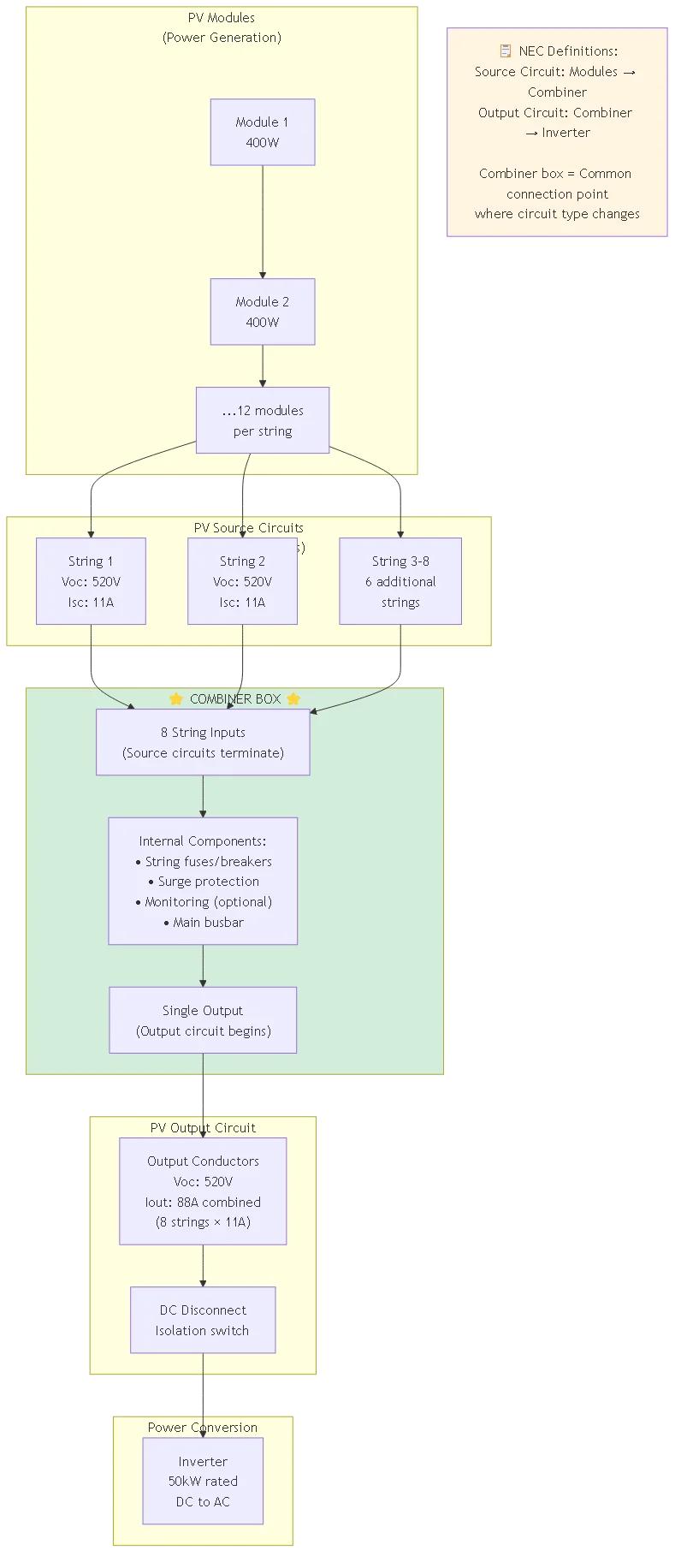
Combiner boxes occupy specific position in photovoltaic system electrical architecture between array field and power conversion equipment. Understanding this position clarifies combiner box relationship to other system components and proper terminology distinguishing source circuits from output circuits per NEC definitions.
PV source circuits originate at modules connecting series-connected panels within single string. Source circuit terminates where multiple strings combine—typically at combiner box input terminals. Artículo 690 de NEC.2 defines PV source circuit as “circuits between modules and from modules to common connection point(s) of the DC system.” These source circuits carry individual string current (typically 8-12A for current module technology).
PV output circuit begins at common connection point (combiner box output) extending to inverter DC input or next combination stage. NEC 690.2 defines PV output circuit as “circuit conductors between the PV source circuit(s) and the inverter or DC utilization equipment.” Output circuit carries combined current from all connected strings (potentially 100-200A or more for large combiners).
This source/output circuit distinction matters for conductor sizing, overcurrent protection requirements, and surge protection specifications. Source circuits on combiner input side follow different code rules than output circuits on combiner output side requiring careful analysis during system design.
| Component | Circuit Type | Voltage Level | Current Level | NEC Requirements |
|---|---|---|---|---|
| String conductors | PV source circuit | String Voc | String Isc × 1.25 | 690.8(B), 690.9 |
| Combiner box | Combination point | System Voc | Transition point | 690.15, 690.17 |
| Output conductors | PV output circuit | System Voc | Sum(Isc) × 1.25 | 690.8(B), 690.31 |
Información clave: Combiner box represents transition boundary between PV source circuits and PV output circuit fundamentally changing electrical characteristics and code requirements. Understanding this transition helps explain why combiner boxes must include specific protective devices and why conductor sizing changes across combiner input versus output connections.
String-level overcurrent protection represents critical combiner box component preventing backfeed current from damaging modules during short-circuit or ground-fault conditions. When multiple strings parallel-connect at combiner busbar, fault on single string could allow all other healthy strings to feed current backward into faulted string potentially exceeding module reverse-current rating and causing permanent damage. String fuses or circuit breakers interrupt this backfeed protecting array investment.
Fuse-based overcurrent protection:
Most combiner boxes use fuses providing economical, space-efficient overcurrent protection. Select fuse rating per NEC 690.9(B) requiring overcurrent device rating minimum 156% of string short-circuit current to prevent nuisance operation during normal conditions yet provide protection during fault events. For string with 11A Isc: minimum fuse rating = 11A × 1.56 = 17.16A—select next standard size 20A fuse.
PV-rated fuses per UL 2579 exhibit specific characteristics differentiating them from general-purpose fuses. PV fuses must interrupt DC fault current at system voltage (600V-1500V typical) without creating sustained arc. They also must withstand continuous current at high ambient temperature (often 60-80°C in combiner boxes) without premature aging. Using non-PV-rated fuses violates NEC 690.16 and creates serious safety hazard potentially causing arc flash or fire.
Circuit breaker overcurrent protection:
Some premium combiner boxes use DC-rated circuit breakers instead of fuses providing resetable protection and integrated disconnect capability. Circuit breakers cost 3-5× more than fuses but eliminate replacement expense after fault events and provide convenient testing/maintenance disconnect. Select breakers rated for DC voltage (not AC breakers incorrectly applied) and appropriate interrupting capacity matching available fault current.
DC circuit breaker ratings must explicitly state DC voltage capability. AC-rated breakers cannot interrupt DC arcs which lack zero-crossing allowing arc extinction—using AC breakers on DC circuits creates extreme fire and explosion hazard. Verify breaker listing includes “DC” rating at system voltage or higher (UL 489 DC-rated, IEC 60947-2 DC-rated).
Central busbar forms electrical spine of combiner box providing common connection point where individual string inputs combine and output circuit originates. Busbar sizing affects system efficiency through resistive losses and determines maximum current handling capability limiting combiner box application range. Professional combiners use copper busbar rated minimum 125% of maximum combined string current providing adequate margin for temperature derating and future expansion.
Busbar construction typically uses flat copper bar stock ranging 5-10mm thick and 20-40mm wide depending on current rating. Calculate minimum busbar cross-sectional area from: Area = (I × 1.25) / J where I is combined string current and J is allowable current density (typically 1.5-2.0 A/mm² for copper with forced ventilation, 1.0-1.5 A/mm² for natural convection cooling).
Example calculation for 8-string combiner with 11A per string:
– Combined current: I = 8 × 11A = 88A
– Design current with margin: 88A × 1.25 = 110A
– Required area at J = 1.5 A/mm²: Area = 110A / 1.5 = 73mm²
– Busbar dimensions: 5mm thick × 15mm wide = 75mm² (adequate)
Busbar insulation prevents accidental contact with energized metal creating shock hazard. Most combiners use heat-shrink tubing, rigid plastic covers, or conformal coating covering all exposed busbar sections except terminal connection areas. Maintain minimum clearance between opposite polarity busbars per NEC 110.26 and manufacturer specifications preventing flashover during transient overvoltage events.
Quality terminal blocks provide reliable, maintainable connections for string input conductors and output circuit conductors. Terminal selection affects installation labor (ease of connection), long-term reliability (contact resistance stability), and troubleshooting convenience (conductor identification and testing access). Professional combiners specify terminals rated for continuous operation at maximum conductor temperature (75°C or 90°C) plus system DC voltage.
Spring-clamp terminals provide tool-free or minimal-tool installation allowing conductors to insert directly into terminal mechanism held by spring pressure. These terminals suit smaller conductors (10-4 AWG typical) used for string connections in residential and small commercial installations. Spring-clamp advantages include fast installation and vibration resistance maintaining connection integrity without retorquing.
Compression terminals serve larger conductors (1/0 AWG and above) typical for combiner output circuits in commercial and utility-scale installations. Compression connection uses mechanical force crimping metal sleeve onto conductor creating gas-tight connection preventing oxidation and maintaining low contact resistance over decades. Compression terminals require special crimping tools adding installation cost but deliver superior long-term reliability for high-current applications.
Advanced combiner boxes include string-level monitoring providing real-time visibility into individual string performance detecting failures or degradation invisible at system level. String monitors measure DC current from each input identifying underperforming strings indicating module damage, soiling, partial shading, or wiring problems. Early detection enables targeted maintenance rather than troubleshooting entire array hunting for problem locations.
String monitoring communicates via Modbus RTU, RS-485, Ethernet, or wireless protocols connecting to central supervisory control and data acquisition (SCADA) system or cloud-based monitoring platform. Data logging captures historical performance trends supporting warranty claims, performance modeling validation, and predictive maintenance scheduling. Utility-scale installations increasingly specify monitoring as standard feature given substantial revenue impact of undetected performance degradation.
Some advanced combiners integrate circuit-level arc fault detection per NEC 690.11 providing enhanced safety protection beyond system-level arc fault detection in inverters. String-level arc fault detection locates fault to specific circuit simplifying troubleshooting and reducing system downtime during fault investigation.
National Electrical Code doesn’t explicitly mandate combiner boxes but establishes requirements effectively necessitating them for systems exceeding certain size or complexity thresholds. Understanding these indirect requirements explains when combiner boxes transition from optional optimization to code-required necessity.
NEC 690.9 overcurrent protection requirements:
When three or more PV source circuits parallel-connect, NEC 690.9(B) requires overcurrent protection on each source circuit preventing reverse-current damage during fault conditions. For systems with 1-2 strings connecting directly to inverter DC input, individual string protection often integrates into inverter eliminating separate combiner box requirement. Systems with 3+ strings require external protection—combiner box provides economical centralized location for required protection devices.
Calculate whether strings require individual overcurrent protection using NEC formula: If (N-1) × Isc > Imax_reverse, protection required. Where N is number of parallel strings, Isc is string short-circuit current, and Imax_reverse is module maximum reverse current rating (typically 2× Isc per module specification). For most practical installations with 3+ strings, this calculation requires protection.
NEC 690.31 conductor ampacity requirements:
String conductors must size per NEC 690.8(B) at minimum 156% of string short-circuit current accounting for temperature derating factors. Without combiner box, each string requires dedicated home-run to inverter sizing all conductors for individual string current. With combiner, only output circuit conductors carry combined current—input string conductors size for individual string current allowing smaller, less expensive wire upstream of combination point.
Example: 8-string system with 11A Isc located 150 meters from inverter:
- Without combiner: 8 conductor pairs × 150m × conductor cost for 14 AWG (1.56 × 11A = 17.16A capacity) = substantial cost
- With combiner: 8 short runs (30m avg) × 14 AWG + 1 long run (150m) × 6 AWG (1.56 × 88A = 137A capacity) = reduced total cost
Combiner boxes provide economic benefit when consolidation reduces total conductor cost, conduit requirements, and labor sufficiently to exceed combiner box equipment cost. This breakpoint analysis determines when combiner boxes transition from optional to financially optimal component.
Residential systems (3-10kW):
Small residential installations with 1-4 strings often omit separate combiner boxes when string locations permit direct inverter connection with reasonable conductor lengths. Many residential inverters include integrated string-level overcurrent protection and DC disconnect eliminating need for external combining. However, rooftop layouts with strings far from inverter mounting location (>30 meters) benefit from rooftop combiner box minimizing long conductor runs.
Decision factors favoring combiner for residential:
– More than 3 strings requiring individual overcurrent protection
– String locations dispersed across rooftop making central collection practical
– Distance from array to inverter exceeds 30 meters
– Code authority requires external DC disconnect accessible without roof access
Commercial systems (10-500kW):
Commercial installations almost universally employ combiner boxes when string count exceeds 4-6 strings. The economic advantage grows with system size as consolidation dramatically reduces conductor and conduit requirements. Commercial systems also benefit from centralized surge protection, monitoring, and disconnect capability supporting maintenance and code compliance.
Utility-scale systems (500kW-100MW+):
Utility-scale installations use distributed combining architecture with multiple “string combiners” throughout array field feeding “recombiners” or central collection equipment. This hierarchical approach minimizes conductor losses while providing redundancy and maintainability. String combiners typically consolidate 8-16 strings, recombiners consolidate 4-8 string combiners, and central inverter stations receive power from one or more recombiners.
| System Scale | Typical String Count | Combiner Strategy | Cost Breakpoint |
|---|---|---|---|
| Residential 3-10kW | 1-4 strings | Optional—often integrated in inverter | If distance >30m or >3 strings |
| Small Commercial 10-50kW | 4-12 strings | Single combiner near array | Typically cost-effective for >4 strings |
| Large Commercial 50-500kW | 12-50+ strings | Multiple combiners or combiner + recombiner | Always economically justified |
| Utility-Scale 500kW+ | 50-1000+ strings | Hierarchical: string combiners → recombiners → central | Essential for economical design |
⚠️ Importante: Don’t confuse economic optimization with code requirements. Even small systems legally requiring individual string overcurrent protection must provide it regardless of economic considerations. Combiner boxes provide code-compliant solution concentrating required protection in accessible, maintainable location. Attempting to save cost by omitting required protection violates NEC and creates dangerous installation.
Combiner box current rating must accommodate combined short-circuit current from all connected strings with appropriate code-mandated safety factors. Undersized combiners create overheating risk, nuisance protection device operation, and potential fire hazard during fault conditions. Proper sizing provides adequate margin ensuring reliable operation under worst-case conditions including simultaneous peak output from all strings on cold, clear day.
Calculate combiner box current rating:
1. Determine string short-circuit current: From module datasheet Isc specification (typically 10-12A for current 400-500W modules)
2. Count maximum connected strings: Number of string input positions on combiner box
3. Calculate combined current: Total = N_strings × Isc
4. Apply NEC 690.8(B) factor: Design current = Total × 1.25
5. Apply temperature derating: If combiner ambient temperature exceeds 30°C, apply NEC 310.15(B)(2)(a) temperature correction
6. Round up to standard rating: Select next standard combiner rating above calculated value
Example for 8-string combiner with 11A Isc modules:
– Combined current: 8 × 11A = 88A
– NEC factor: 88A × 1.25 = 110A minimum
– Standard rating: Select 125A combiner providing margin
Some designers apply additional 25% “growth factor” allowing future string additions without replacing combiner. This 1.56× total factor (1.25 NEC × 1.25 growth) provides flexibility but increases initial cost. Evaluate growth factor based on project-specific expansion likelihood and available roof space.
Combiner box voltage rating must exceed maximum system open-circuit voltage including temperature compensation. Photovoltaic module voltage increases significantly at low temperatures potentially exceeding nominal system voltage by 15-20%. Voltage ratings represent critical safety parameter—inadequate voltage rating risks insulation breakdown, flashover, or personnel shock hazard.
Standard DC voltage ratings:
- 600V class: Suitable for systems with Voc ≤600V (typically 10-12 modules per string with 48-52V Voc modules)
- 1000V class: Suitable for systems with Voc ≤1000V (typically 18-20 modules per string)
- 1500V class: Utility-scale systems with Voc ≤1500V (typically 28-32 modules per string)
Calculate maximum system voltage per NEC 690.7(A) methodology:
1. Identify module Voc at standard test conditions (STC) from datasheet
2. Find module temperature coefficient for Voc (typically −0.28% to −0.35%/°C)
3. Determine coldest expected ambient temperature at installation site
4. Calculate temperature-compensated Voc: Voc(cold) = Voc(STC) × [1 + β(T_cold − 25°C)]
5. Add 5-10% safety margin
6. Select next standard voltage class above calculated maximum
Example: 12-module string using 50V Voc modules with −0.30%/°C coefficient, coldest temperature −25°C:
– String Voc(STC): 12 × 50V = 600V
– Temperature factor: 1 + (−0.003)(−25 − 25) = 1 + (−0.003)(−50) = 1.15
– Cold temperature Voc: 600V × 1.15 = 690V
– With 5% margin: 690V × 1.05 = 725V
– Required rating: Specify 1000V class combiner (600V class inadequate)
Combiner box enclosure protects internal components from weather, dust, moisture, and mechanical damage while providing safe electrical installation meeting code clearance and access requirements. Environmental rating selection depends on installation location and exposure conditions determining appropriate ingress protection (IP) rating or NEMA enclosure type.
Common enclosure ratings for combiner boxes:
NEMA 1 (Indoor use, general purpose): Suitable for climate-controlled inverter rooms or electrical equipment buildings. Protects against dust and incidental contact but not weather exposure. Lowest cost option appropriate only for fully protected indoor locations.
NEMA 3R (Outdoor, rain resistant): Most common rating for rooftop and outdoor combiner installations. Protects against falling rain, sleet, and external ice formation. Does not seal against wind-driven dust or pressurized water spray. Adequate for most commercial rooftop installations.
NEMA 4 (Outdoor, watertight): Sealed enclosure protecting against wind-driven rain, splashing water, hose-directed water, and external ice formation. Required for harsh weather exposure including coastal installations, wash-down areas, or utility-scale ground-mount systems requiring periodic equipment cleaning.
NEMA 4X (Outdoor, corrosion-resistant): Provides NEMA 4 protection plus corrosion resistance using stainless steel or coated aluminum construction. Specifies for coastal installations, industrial environments with chemical exposure, or locations with severe corrosion potential. Costs 40-60% more than standard NEMA 3R but provides decades longer service life in corrosive environments.
Enclosure material affects both environmental protection and thermal performance. Steel enclosures cost less but require powder coating or galvanizing for corrosion protection. Aluminum enclosures resist corrosion naturally and dissipate heat better than steel improving internal component cooling. Polycarbonate plastic enclosures provide excellent corrosion resistance and UV stability but limit size due to structural strength constraints.
Some systems eliminate combiner boxes connecting strings directly to inverter DC inputs when practical. This approach suits smaller installations with 1-4 strings located near inverter mounting location where dedicated conductor runs remain economical. Modern string inverters and some central inverters include integrated string-level overcurrent protection, monitoring, and surge protection eliminating external combiner requirement.
Advantages of direct connection:
– Eliminates combiner box equipment cost ($300-2000 depending on size)
– Reduces one potential failure point in system
– Simplifies installation for accessible inverter locations
– Leverages integrated inverter protection and monitoring features
Disadvantages of direct connection:
– Requires longer conductor runs if strings dispersed across large area
– May necessitate oversized conduits accommodating multiple conductor pairs
– Troubleshooting more difficult without central test point
– String additions or changes require inverter shutdown and DC termination work
Large installations use hierarchical combining with “string combiners” consolidating 8-16 strings then “recombiner” combining multiple string combiner outputs. This two-stage approach optimizes conductor sizing preventing excessive current in any single conductor while maintaining centralized protection and monitoring at each combination stage.
Recombiners typically omit individual input overcurrent protection since incoming conductors already protect at string combiner level. However, recombiners include output overcurrent protection, main DC disconnect, surge protection, and system-level monitoring. Some designs integrate inverter stations with recombiner function combining DC consolidation and AC conversion in single equipment pad.
Alternative topology runs individual strings as home-runs to central junction location near inverter using oversized junction box or terminal cabinet instead of purpose-built combiner. This approach provides flexibility for systems with uncertain final configuration or phased deployment plans. However, generic junction boxes typically lack integrated protection requiring separate fuse holders, surge protection, and disconnect switches increasing total cost and complexity.
Optimal combiner box location balances electrical performance, installation cost, maintenance access, and code compliance. Poor location selection creates long-term problems including difficult troubleshooting, inaccessible maintenance, and excessive conductor runs negating combiner benefits.
Electrical performance considerations:
– Minimize total conductor length from strings to combiner to inverter
– Position combiner near geometric center of array field reducing average string length
– Locate where ambient temperature remains relatively cool improving component reliability
– Avoid locations near heat sources (HVAC exhausts, vent stacks) raising internal temperature
Installation and maintenance access:
– Provide clear working space per NEC 110.26 (minimum 900mm width × 1000mm depth)
– Ensure safe access without requiring ladders for routine inspection
– Position at comfortable working height (1.2-1.8m above standing surface) for panel access
– Avoid locations requiring roof access for inspection where alternative grade-level access possible
Code compliance factors:
– Install where visible and accessible to emergency responders per NEC 690.13
– Provide required labeling visible from combiner location identifying as PV equipment
– Ensure ground-fault detection equipment can function if required per NEC 690.41
– Verify installation location satisfies authority having jurisdiction requirements
Weather and environmental protection:
– Orient enclosure door away from prevailing weather direction minimizing water intrusion
– Provide shade where possible reducing thermal stress and internal temperature
– Elevate above expected snow accumulation, flood levels, or ground moisture
– Install where mechanical damage risk minimized (away from traffic, material handling)
Proper wiring technique ensures reliable combiner box operation and simplifies troubleshooting. Poor wiring creates confusion, increases installation time, and makes future modifications difficult.
Color-coding and labeling standards:
– Use red (or red-striped) conductors for positive DC connections
– Use white or gray conductors for negative DC grounded conductor
– Use green or bare conductors for equipment grounding only—never current-carrying circuits
– Label each string input at terminal block matching string identification on roof plan
– Use permanent labeling (Brady labels, Dymo embossed, engraved tags) not handwritten markers
Terminal torque requirements:
– Use calibrated torque screwdriver or torque wrench per manufacturer specifications
– Typical torque: 0.5-1.2 N⋅m for string terminals, 4-6 N⋅m for main output lugs
– Mark torqued connections with paint stripe allowing visual verification of proper initial torque
– Recheck torque after 30 days operation accounting for thermal cycling and settling
Conductor routing and strain relief:
– Route all conductors with smooth bends—no sharp angles stressing insulation
– Group positive and negative conductors from each string using cable ties maintaining pair identity
– Provide strain relief at enclosure entry preventing conductor weight from stressing terminals
– Leave 150-300mm service loop inside enclosure allowing terminal access without conductor tension
Commission combiner box before energizing complete PV system verifying proper installation and identifying errors correctable without troubleshooting under power.
Pre-energization tests:
1. Continuity check: Verify electrical continuity from each input terminal through protection device to main busbar
2. Resistencia del aislamiento: Measure >1MΩ between positive busbar and ground, negative busbar and ground
3. Verificación de polaridad: Confirm positive strings connect to positive busbar, negative to negative
4. Ground resistance: Test equipment ground path shows <1Ω to main system ground electrode Energization procedure:
1. With modules covered, verify zero voltage at all combiner inputs
2. Uncover one string verifying expected voltage appears at corresponding input terminals
3. Observe SPD status indicators showing normal operation
4. Sequentially uncover remaining strings verifying voltage appears at each input
5. Measure combined output voltage matching individual string voltage
6. Measure output current approximating sum of string currents (within 10%)
Performance verification:
7. Monitor combiner temperature under full sun—internal temperature should stabilize <60°C above ambient 8. Verify string monitoring (if equipped) reports reasonable individual string currents 9. Document all test results with photographs for commissioning record 10. Obtain electrical inspector approval if required by jurisdiction
| Parámetro de prueba | Rango aceptable | Test Equipment | Action if Failed |
|---|---|---|---|
| Resistencia del aislamiento | >1MΩ @ 500VDC | Megohmmeter | Check for crossed wires, damaged insulation |
| Ground Continuity | <1Ω to ground electrode | Multimeter | Inspect ground connections, verify bonding |
| String Voltage | ±5% of design Voc | Multimeter (DC 1000V) | Check module count, verify connections |
| Cadena Corriente | ±10% of expected based on irradiance | DC clamp meter | Investigate shading, module issues |
| Internal Temperature | Infrared thermometerCheck ventilation, inspect for hot spots |
Consejo profesional: Create site-specific combiner box commissioning checklist documenting all required tests and acceptance criteria. Use tablet or smartphone app allowing real-time photo documentation attached to test results creating complete commissioning record. This documented evidence proves proper installation during warranty claims and provides baseline for future performance comparison troubleshooting degradation issues.
A combiner box consolidates multiple photovoltaic source circuits (strings) into single output circuit providing practical and economic benefits. Instead of routing each string separately from array to inverter requiring numerous long conductor runs, short string conductors connect to nearby combiner box then single output circuit completes run to inverter. This consolidation dramatically reduces conductor cost, conduit requirements, and installation labor especially for systems with more than 3-4 strings.
Beyond consolidation, combiner boxes provide centralized location for code-required protective devices including string-level overcurrent protection preventing backfeed current damage, surge protective devices defending against lightning transients, and disconnect switches enabling safe maintenance. This concentrated protection function reduces cost versus providing individual protection at each string while maintaining NEC compliance and safety.
For systems with 3+ strings located more than 30 meters from inverter, combiner boxes typically provide net cost savings even accounting for equipment expense. Commercial and utility-scale installations universally use combiners given dramatic reduction in conductor and installation costs compared to individual home-run approach.
Not all solar installations require separate combiner boxes. Small residential systems with 1-2 strings can connect directly to inverter when located nearby (within 20-30 meters) avoiding combiner expense. Many modern string inverters include integrated string-level overcurrent protection, monitoring, and surge protection eliminating external combiner requirement for small systems.
However, NEC 690.9 requires individual string overcurrent protection when three or more source circuits parallel-connect. For systems exceeding this threshold, combiner box provides code-compliant centralized protection location. Even when not code-mandated, combiner boxes often make economic sense when consolidation reduces total conductor cost and installation labor exceeding combiner equipment expense.
Authority having jurisdiction may require combiner boxes regardless of technical necessity based on local amendments or inspection preferences. Consult with electrical inspector early in design process clarifying whether combiner boxes are expected for your installation avoiding costly redesign during plan review.
Size combiner box based on three primary parameters: current rating, voltage rating, and number of string inputs. Current rating must accommodate combined short-circuit current from all strings per NEC 690.8(B): Combined Isc × 1.25 minimum. For eight 11A strings: 8 × 11A × 1.25 = 110A minimum—select 125A or 150A rated combiner providing margin.
Voltage rating must exceed maximum system open-circuit voltage including temperature compensation per NEC 690.7. Calculate string Voc at coldest expected temperature then select next standard voltage class: 600V, 1000V, or 1500V. String count must match or exceed number of strings requiring combination with allowance for future expansion if anticipated.
Consider additional selection factors including enclosure environmental rating (NEMA 1, 3R, 4, or 4X) based on installation location, desired optional features (surge protection, monitoring, disconnect), and physical size constraints at mounting location. Request manufacturer sizing assistance providing string count, current, voltage, and application details ensuring optimal combiner selection.
Combiner boxes consolidate individual PV source circuits (strings) at first combination stage—the transition point where source circuits terminate and output circuit begins. Combiner inputs connect to string conductors from array while combiner output feeds to inverter or next combination stage. Combiners include individual string overcurrent protection since each input represents separate source circuit requiring protection per NEC 690.9.
Recombiner boxes represent second combination stage consolidating outputs from multiple first-stage combiners. Recombiner inputs already have upstream overcurrent protection at string level so individual input protection often omits. However, recombiners include output overcurrent protection, main disconnect, surge protection, and system monitoring appropriate for their role as central collection point before inverter.
This hierarchical combining architecture suits large installations where total string count (50-200+ strings) makes single-stage combination impractical. Two-stage approach (string combiners → recombiner → inverter) optimizes conductor sizing, maintains appropriate protection coordination, and provides distributed monitoring throughout array field.
Using standard electrical junction box instead of purpose-built PV combiner creates numerous problems and likely violates NEC requirements. Regular junction boxes typically lack: DC voltage ratings appropriate for PV systems (often rated only 300-600V AC), space for required string overcurrent protection devices, listings or certifications for PV applications per UL 1741, and appropriate current-carrying capacity for combined string current.
NEC 690.4(D) requires PV system equipment to be “identified for the application” meaning listed and labeled for photovoltaic use. Generic junction boxes don’t meet this requirement. Additionally, installing string fuses or circuit breakers in generic junction box creates unlisted assembly violating listing requirements for overcurrent protective device installation.
Purpose-built PV combiner boxes include factory-installed components properly rated, spaced, and integrated meeting all NEC requirements with single product listing. While initial cost higher than generic junction box, combiner boxes provide code-compliant solution avoiding inspection rejection and providing reliable long-term operation. The modest cost difference ($300-500 vs $50-100 for generic box) represents worthwhile investment for proper installation.
Commercial combiner box location should balance electrical performance, installation cost, and maintenance accessibility. Optimal mounting near geometric center of array field minimizes average string length reducing voltage drop and conductor cost. Consider mounting on roof penetrations (elevator shafts, stairwell penthouses) providing structural support and weather protection while remaining accessible for maintenance without requiring ladder access to open roof.
Wall-mounted combiner installations on building exterior below roofline provide excellent accessibility allowing inspection and maintenance from grade level or intermediate platforms without roof access. This mounting approach suits installations where combiner output can route directly through wall to interior inverter equipment room eliminating long rooftop conductor runs.
NEC 110.26 requires working space minimum 900mm wide × 1000mm deep with adequate headroom (typically 2000mm minimum) for equipment rated above 150V to ground. Verify selected location provides required working space accounting for adjacent equipment, structural obstructions, and safe access paths. Document combiner location on drawings ensuring electrical inspector can verify code-compliant installation during review.
Implement quarterly visual inspection schedule checking combiner box status indicators, physical condition, and signs of overheating or damage. Quarterly inspection takes 10-15 minutes per combiner documenting equipment condition and identifying issues before they cause system downtime. Check string fuse or breaker status, SPD indicators, monitoring system readings (if equipped), and enclosure integrity including gasket condition and water intrusion signs.
Annual comprehensive inspection supplements quarterly visual checks with electrical testing. Measure string voltages and currents verifying balanced performance across all inputs. Test insulation resistance confirming >1MΩ between busbars and ground. Inspect terminal torque using torque wrench checking 10-15% of connections—retorque if significant loosening detected. Use infrared camera scanning for hot spots indicating poor connections or overloaded components.
After major weather events (severe thunderstorms, hurricanes) perform special inspection checking for storm damage, water intrusion, or surge activation indicated by SPD status changes. Document all inspections with photographs and test data creating historical record supporting warranty claims and tracking degradation trends requiring preemptive component replacement.
Combiner boxes represent essential photovoltaic system component consolidating multiple source circuits into single output circuit while providing centralized overcurrent protection, surge protection, and system monitoring. Understanding combiner box functions, internal components, sizing methodology, and installation requirements enables proper specification and application for residential through utility-scale solar installations.
Principales conclusiones:
1. Combiner boxes consolidate PV source circuits at transition point to output circuit reducing conductor requirements and providing centralized protection location
2. Internal components include string overcurrent protection, main busbar assembly, terminal blocks, and optional monitoring/surge protection
3. NEC 690.9 requires individual string protection when three or more circuits parallel-connect effectively mandating combiners for most systems above 10kW
4. Size combiner current rating at combined string Isc × 1.25 minimum with voltage rating exceeding temperature-compensated maximum Voc
5. Installation location should balance electrical performance, installation cost, maintenance accessibility, and NEC working space requirements
Proper combiner box selection and installation directly affects PV system reliability, code compliance, and long-term maintenance costs. Investment in appropriately sized, properly located, and professionally installed combiner boxes pays dividends through reliable operation, simplified troubleshooting, and reduced conductor installation costs over 25-year system lifetime.
Recursos relacionados:
- PV Combiner Box Components: Complete Assembly Guide
- DC SPD for Solar Systems: String Protection Integration
- DC Circuit Breaker Selection for Combiner Boxes
Ready to specify combiner boxes for your solar projects? Contact our photovoltaic system design team for application-specific combiner sizing, component selection, and installation guidance ensuring code-compliant, cost-effective solar installations.
Última actualización: Noviembre de 2025
Autor: Equipo técnico de SYNODE
Revisado por: PV System Design Department