Dirección
304 North Cardinal
Dorchester Center, MA 02124
Horas de trabajo
De lunes a viernes: de 7.00 a 19.00 horas
Fin de semana: 10.00 A 17.00 HORAS
Dirección
304 North Cardinal
Dorchester Center, MA 02124
Horas de trabajo
De lunes a viernes: de 7.00 a 19.00 horas
Fin de semana: 10.00 A 17.00 HORAS

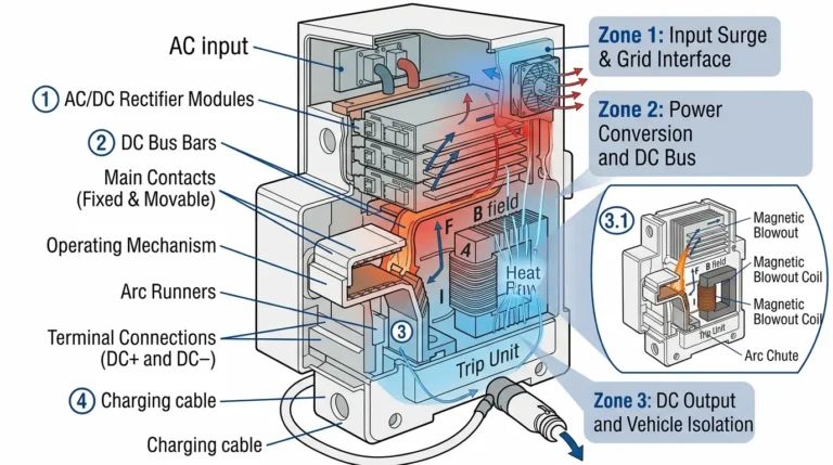
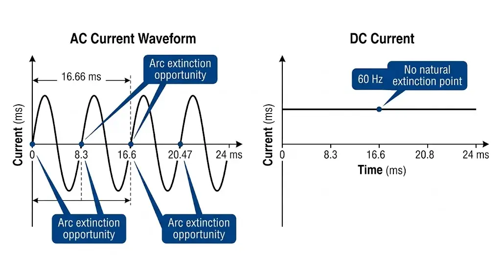
Un disyuntor de CC es un dispositivo de conmutación de protección diseñado para interrumpir condiciones de fallo de corriente continua en sistemas fotovoltaicos, almacenamiento de energía en baterías e infraestructuras de carga de vehículos eléctricos. A diferencia de los disyuntores de CA, que se benefician del cruce por cero de la corriente cada 8,3 ms (a 60 Hz), los disyuntores de CC deben extinguir por la fuerza un arco sostenido que puede alcanzar temperaturas superiores a 6000 °C, lo que hace que su diseño sea fundamentalmente más complejo.
Esta distinción es importante. En una instalación solar sobre tejado de 48 MW en 12 edificios comerciales de la provincia de Jiangsu (2024), los disyuntores de 1000 VCC a nivel de ramal redujeron la duración del arco eléctrico de 180 ms a menos de 12 ms, evitando daños térmicos en las cajas de conexiones y eliminando intervenciones de mantenimiento no planificadas durante dos temporadas de verano.
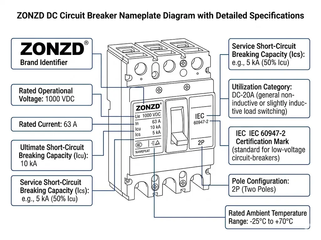
Los disyuntores de CC para aplicaciones industriales y comerciales entran dentro de la categoría IEC 60947-2, que especifica los requisitos de ensayo para la capacidad de conmutación de CC, incluida la capacidad de cierre y corte a la tensión nominal de CC. La función principal sigue siendo la misma en todos los tipos: detectar la corriente anormal, separar mecánicamente los contactos, gestionar el arco resultante y restaurar la integridad del aislamiento, todo ello en milisegundos.
El reto fundamental reside en la persistencia del arco. Un arco de CA se extingue de forma natural en cada cruce por cero de la corriente, lo que ocurre entre 100 y 120 veces por segundo. Un arco de CC se mantiene continuamente hasta que interviene una fuerza externa.
Esto crea tres problemas de ingeniería:
Los sistemas fotovoltaicos modernos funcionan con tensiones de cadena de hasta 1.500 VCC (a escala comercial) o 1.000 VCC (comercial). Los sistemas de almacenamiento de energía suelen funcionar a 48-800 VCC, mientras que los cargadores rápidos de CC para vehículos eléctricos funcionan a 200-1000 VCC. Un disyuntor clasificado para 250 VCA no puede interrumpir de forma segura 250 VCC, ya que el arco de CC se mantendrá a través del hueco de contacto, lo que podría provocar un embalamiento térmico.
Compruebe siempre la tensión nominal de CC (Ue CC) en la placa de características, no sólo la tensión nominal de CA.
Comprender la arquitectura interna revela por qué Disyuntores de CC cuestan más y pesan más que sus equivalentes de CA.
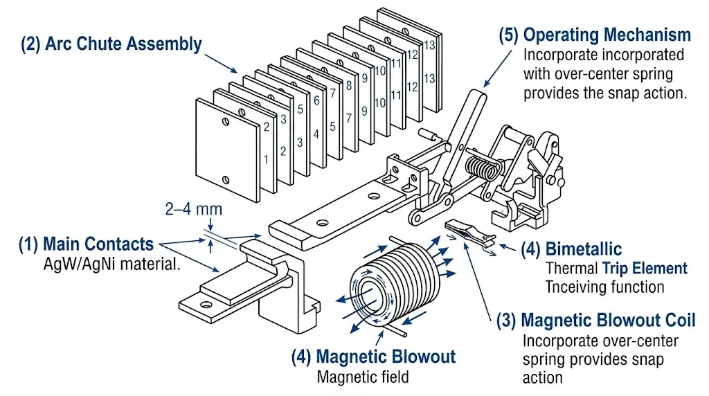
Los elementos conductores de corriente primaria utilizan aleaciones especializadas para la resistencia al arco:
La separación entre contactos en los interruptores de CC suele ser de 2-4 mm por polo para los magnetotérmicos y de 8-15 mm para los magnetotérmicos, significativamente mayor que la de los equivalentes de CA para evitar la reconexión del arco.
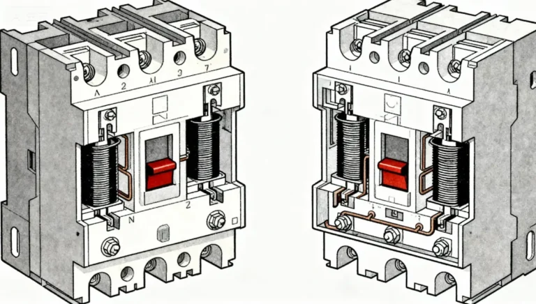
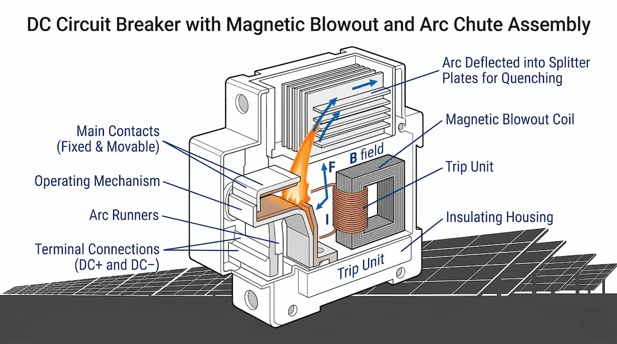
La canaleta de arco es el componente definitorio que separa los disyuntores de CC de los diseños de CA:
Cada placa divisora introduce aproximadamente 20-30 V de caída de tensión del arco. Una canaleta de arco de 13 placas añade 260-390 V a la tensión total del arco, lo que ayuda a forzar la corriente a cero.
Los imanes permanentes o electroimanes generan un campo magnético de 50-200 mT perpendicular a la columna del arco. Por la fuerza de Lorentz (F = BIL), el arco es impulsado hacia el conducto del arco a velocidades de hasta 150 m/s. Esta acción alarga la trayectoria del arco, lo enfría por contacto con las placas divisoras y acelera la desionización del plasma.
Los interruptores de CC emplean dos mecanismos de disparo principales que funcionan de forma coordinada:
El disparo térmico (protección contra sobrecarga) utiliza una banda bimetálica que se calienta y se dobla proporcionalmente a I²t. Las curvas de disparo siguen las clasificaciones IEC 60898-3: Curva B dispara a 3-5× In, curva C a 5-10× In, curva D a 10-20× In.
El disparo magnético (protección contra cortocircuitos) utiliza una bobina magnética que genera una fuerza de disparo instantánea cuando la corriente de defecto supera el umbral. Tiempo de respuesta: normalmente 5-20 ms para corrientes superiores a 10× In.
El mecanismo basculante almacena energía durante el funcionamiento en ON y la libera durante el disparo. Los elementos clave incluyen un muelle sobrecentrado para la separación de los contactos por acción brusca (velocidad mínima de 1,2 m/s), un varillaje sin disparo que evita que los contactos se mantengan cerrados durante los fallos y una ventana de indicación que muestra el estado ON/OFF/TRIPPED.
[Expert Insight: Arc Chute Design]
- El número de placas está directamente relacionado con la tensión nominal: se añaden aproximadamente 2 placas por cada 100 VCC de aumento de la tensión nominal.
- Las placas cerámicas superan a las de acero en aplicaciones de conmutación de alta frecuencia, pero cuestan 40-60% más
- La contaminación de la canaleta de arco por el polvo ambiental reduce la capacidad de rotura hasta 15%-especifique IP65 como mínimo para instalaciones exteriores
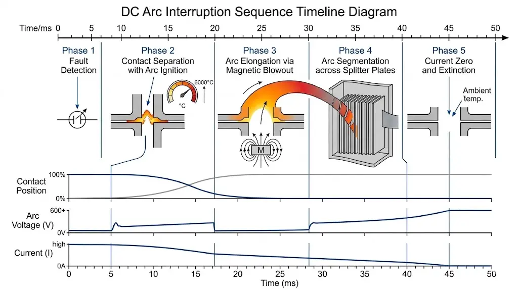
La secuencia de interrupción se produce en aproximadamente 10-50 ms para los interruptores magnetotérmicos y 20-80 ms para los MCCB. Cada fase se basa en la anterior.
El elemento térmico comienza a calentarse (sobrecarga) o la bobina magnética se activa (cortocircuito). Para un fallo de 10 kA en un interruptor de 63 A, el disparo magnético se inicia en 3 ms.
El mecanismo de disparo se libera. El muelle separa los contactos a 1,2-2,5 m/s. El arco se enciende inmediatamente: la tensión inicial del arco es de aproximadamente 20-40 V.
El soplado magnético impulsa el arco hacia la canaleta de arco. La longitud del arco pasa de los 2 mm iniciales a 50-100 mm. La tensión del arco aumenta hasta 300-600 V.
El arco entra en las placas divisoras, dividiéndose en 10-20 arcos en serie. La tensión total del arco supera ahora la tensión del sistema (por ejemplo, 800 V de tensión del arco frente a 600 V CC del sistema).
Cuando la tensión del arco supera la tensión del sistema, la corriente es forzada hacia cero. La extinción final se produce cuando el plasma del arco se enfría por debajo de la temperatura de ionización (~4000 K). La resistencia posterior al arco debe ser superior a 1 MΩ en 100 ms para evitar la reignición.
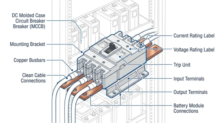
La elección entre disyuntores en miniatura (MCB) y disyuntores de caja moldeada (MCCB) depende de la capacidad de corriente de su sistema y de los requisitos de protección.
| Parámetro | DC MCB | DC MCCB |
|---|---|---|
| Gama actual | 1-63 A | 16-1250 A |
| Tensión nominal | Hasta 1000 VDC | Hasta 1500 VDC |
| Capacidad de rotura | 6-10 kA | 10-50 kA |
| Ajuste del viaje | Fijo | Ajustable (térmica y magnética) |
| Aplicación típica | Protección de cuerdas | Desconexión principal |
| Montaje | Carril DIN (35 mm) | Montaje en panel o carril DIN |
Para la protección a nivel de cadena en un sistema FV de 1000 VCC con una corriente de cadena de 15 A, se necesita una protección de 2 polos. DC MCB de 1000 V CC / 20 A / 10 kA proporciona la protección adecuada. Para el seccionador principal de CC delante de un inversor central de 500 kW, se necesita un DC MCCB con capacidad nominal de 1500 VCC / 800 A / 50 kA y ajustes de disparo ajustables ofrece la capacidad y selectividad necesarias.
[Perspectiva del experto: Errores de selección]
- Nunca dimensione los disyuntores basándose únicamente en la ampacidad del cable; ajústelos a la corriente de carga real más un margen de 25%.
- Los interruptores magnetotérmicos con relés electrónicos ofrecen una precisión de ±5% frente a ±20% de los termomagnéticos.
- En aplicaciones de almacenamiento de baterías, verifique la clasificación bidireccional; algunos disyuntores de CC son sensibles a la polaridad.
Debe ser igual o superior a la tensión máxima del sistema en todas las condiciones. Para sistemas FV, calcule Voc_max utilizando coeficientes de temperatura: un sistema nominal de 1000 VCC puede alcanzar 1100 VCC a -10°C. Especifique disyuntores con Ue ≥ 1100 VCC o aplique la reducción de potencia adecuada.
Icu (capacidad última de corte) indica que el interruptor puede interrumpir pero no seguir funcionando. Ics (capacidad de corte de servicio) significa que puede interrumpir y seguir funcionando. En las aplicaciones fotovoltaicas, la corriente de fallo prevista depende de la contribución del inversor y del número de cadenas en paralelo: normalmente 6-15 kA para inversores de cadena, 20-50 kA para inversores centrales.
Según IEC 60947-2: DC-20A cubre las cargas resistivas, DC-20B cubre las cargas inductivas, DC-21A y DC-21B abordan las aplicaciones de conmutación frecuente. Los sistemas fotovoltaicos se suelen clasificar como DC-20A; los ESS con contactores pueden requerir la clasificación DC-21B.
A diferencia de los sistemas de CA, la polaridad de CC es importante. Un disyuntor de 2 polos interrumpe tanto el positivo como el negativo, lo que es estándar para la mayoría de las aplicaciones de CC. Para sistemas FV sin conexión a tierra de 1000 VCC, un disyuntor de 2 polos con 500 VCC por polo (conectado internamente en serie) proporciona una interrupción total de la tensión del sistema.
Cuando se combinan interruptores de CC con Fusibles CC para la protección de reserva, asegúrese de que la I²t del fusible sea inferior al umbral de daño térmico del disyuntor.
Los disyuntores de CC sirven para múltiples puntos de protección en instalaciones fotovoltaicas: protección de cadenas para el aislamiento individual de cadenas en Cajas de conexiones fotovoltaicas, Desconexión de salida del combinador entre el combinador y el inversor, y desconexión de entrada de CC del inversor según los requisitos de NEC 690.15.
En una instalación de montaje en tierra de 30 MW en Ningxia (2023), los interruptores magnetotérmicos de CC a nivel de cadena permitieron al personal de mantenimiento aislar cadenas individuales en menos de 2 minutos, en comparación con los más de 15 minutos que se tardaba cuando se utilizaban únicamente desconectadores a nivel de combinador.
Los sistemas de baterías requieren disyuntores de CC dimensionados para el flujo de corriente bidireccional durante los ciclos de carga/descarga. Otras consideraciones son la corriente de cortocircuito de la batería (que puede superar los 20 kA en el caso de los bancos de iones de litio), el riesgo de arco eléctrico debido a la corriente de defecto de CC sostenida y la capacidad de disparo remoto para la integración de BMS.
Los cargadores rápidos de CC (50-350 kW) incorporan disyuntores de CC para la protección de la salida del rectificador entre el convertidor de CA/CC y el cable de carga, detección de fallo a tierra para fallos de aislamiento y capacidad de desconexión de emergencia durante los fallos.
Para seleccionar el disyuntor de CC adecuado es necesario adaptar los valores nominales de tensión, la capacidad de corte y las características de disparo a los parámetros específicos de su sistema. Los disyuntores subdimensionados crean riesgos para la seguridad; las unidades sobredimensionadas derrochan presupuesto y pueden no proporcionar una sensibilidad de protección adecuada.
Sinobreaker's Disyuntor de CC abarca desde interruptores magnetotérmicos de nivel de string de 6 A hasta interruptores magnetotérmicos de desconexión principal de 1250 A, todos ellos probados según IEC 60947-2 y certificados para aplicaciones fotovoltaicas, de almacenamiento de energía y de carga de vehículos eléctricos.
Para obtener asistencia en el diseño de sistemas o en la selección de productos, póngase en contacto con nuestro equipo de ingeniería e indíquenos las especificaciones de su proyecto.
Los disyuntores de CC utilizan conductos de arco especializados y sistemas de soplado magnético para forzar la extinción del arco, mientras que los disyuntores de CA confían en los cruces por cero naturales de la corriente que se producen entre 100 y 120 veces por segundo para extinguir los arcos con diseños más sencillos.
Los disyuntores de CA carecen de la capacidad de interrupción de arcos para arcos de CC sostenidos y es probable que no despejen las faltas, creando riesgos de incendio y daños en los equipos, incluso con valores nominales de tensión equivalentes.
Los magnetotérmicos de CC suelen cubrir hasta 1.000 VCC para aplicaciones solares comerciales, mientras que los magnetotérmicos de CC llegan hasta 1.500 VCC para instalaciones fotovoltaicas a gran escala y de almacenamiento de energía de alta tensión.
La respuesta de disparo magnético se produce normalmente en 5-20 ms para corrientes de defecto superiores a 10× la corriente nominal, con extinción total del arco completada en 10-50 ms para los magnetotérmicos y 20-80 ms para los magnetotérmicos.
La mayoría de los interruptores de CC son sensibles a la posición debido a la dirección magnética de soplado; siga siempre las marcas del fabricante para los terminales de línea/carga y mantenga el montaje vertical dentro de un margen de ±5° a menos que se indique explícitamente el funcionamiento horizontal.
Calcule la posible corriente de fallo en función de la configuración de su sistema: normalmente, de 6 a 15 kA para instalaciones de inversores en cadena y de 20 a 50 kA para sistemas de inversores centrales con varios combinadores en paralelo.
Realice una inspección visual y una verificación del par de apriete de los terminales anualmente; realice pruebas de disparo funcional cada 24-36 meses. Sustituya cualquier disyuntor que muestre daños visibles en el arco, decoloración o que no supere las pruebas de tiempo de disparo.