Dirección
304 North Cardinal
Dorchester Center, MA 02124
Horas de trabajo
De lunes a viernes: de 7.00 a 19.00 horas
Fin de semana: 10.00 A 17.00 HORAS
Dirección
304 North Cardinal
Dorchester Center, MA 02124
Horas de trabajo
De lunes a viernes: de 7.00 a 19.00 horas
Fin de semana: 10.00 A 17.00 HORAS

A Fusible CC in an EV charging system must interrupt high-magnitude direct current without a natural zero crossing — the property that makes AC overcurrent protection more straightforward. In DC circuits, sustained arc energy can exceed 10 kJ at 1000 VDC bus voltages, demanding fuse designs engineered specifically for unidirectional fault current extinction.
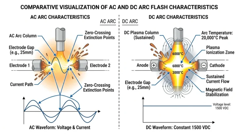
AC fuses benefit from current reversing polarity at 50–60 Hz, naturally extinguishing the arc twice per cycle. DC fuses have no such advantage. Once a fault arc ignites inside the fuse element, it must be forcibly quenched through arc elongation, sand-fill quenching media, and calibrated element geometry. In EV fast-charging architectures operating at 800–1000 VDC battery bus voltages, the prospective short-circuit current at the DC busbar commonly reaches 20–50 kA, depending on cable impedance and battery pack internal resistance.
IEC 60269-4 governs fuses for semiconductor protection in DC applications, specifying I²t limits that protect downstream IGBT modules and power electronics from thermal destruction during fault clearance.
EV charging introduces bidirectional power flow in Vehicle-to-Grid-capable stations, dynamic load cycling as battery state-of-charge changes, and high inrush currents during charger initialization — sometimes reaching 3–5× rated current for 50–200 ms. In a 60 MW public fast-charging hub project in Zhejiang Province (2024), engineers reported that standard industrial DC fuses rated for steady-state loads failed pre-qualification thermal cycling tests, requiring replacement with fuses validated under repetitive pulse load profiles.
Selecting the right gPV fuse or dedicated EV-rated DC fuse means accounting for these dynamic conditions.
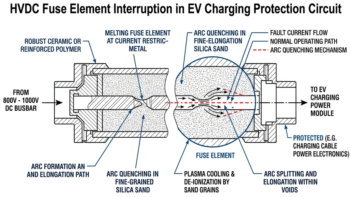
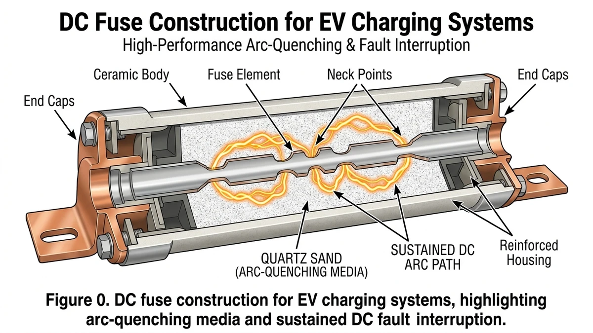
Inside the fuse body, interruption depends on materials, geometry, and pressure containment working in sequence rather than on a single melting event.
A high-current DC fuse contains three functional layers working together:
The interruption process follows four phases:
Step 1 — Pre-arcing: Overcurrent heats the element; notched sections reach melting point first, creating multiple simultaneous break points that distribute arc energy.
Step 2 — Arc ignition: Plasma forms across each gap at temperatures approaching 6000°C. In DC circuits, this arc is self-sustaining without active quenching.
Step 3 — Arc quenching: Quartz sand contacts the plasma, rapidly extracting thermal energy. The sand melts and vitrifies, forming a resistive fulgurite that drives arc voltage above system voltage.
Step 4 — Current interruption: Arc voltage exceeds supply voltage; current collapses to zero. IEC 60269-1 governs this full clearing sequence, defining both pre-arcing and arcing I²t limits.
In a 60 MW ground-mount installation in Inner Mongolia (2023), undersized fuses with insufficient quartz fill density failed to clear a 1500 VDC fault within the rated arcing time. Properly rated gPV fuses cleared the same fault condition in under 8 ms.
[Expert Insight]
– If a fuse family offers multiple body sizes at the same ampere rating, check the larger body’s thermal mass and clearing curve before defaulting to the smaller footprint.
– Request pre-arcing and total clearing I²t data at your actual DC voltage, not just nominal catalog values.
– In repeated pulse-load applications, ask for manufacturer test evidence tied to cycling duty rather than steady-state current alone.
Real charger performance is determined by temperature, enclosure layout, and fault level, so the printed rating is only the starting point for selection.
DC fuse voltage ratings must meet or exceed the maximum open-circuit voltage of the circuit, including transient spikes. For Level 2 AC-coupled chargers with a 400–800 V DC bus, a 1000 VDC-rated fuse is the standard minimum. DC fast chargers operating at 800–1000 V output typically use 1500 VDC-class fuses to maintain margin under abnormal and transient conditions. IEC 60269-6 governs gPV-class fuses for DC applications and specifies that the rated voltage must not be less than 1.1× the maximum system voltage under operating conditions.
For a deeper look at how DC fuse families are classified by voltage class, the DC fuse product overview covers the full range from 500 VDC to 1500 VDC.
Nameplate current is valid only at 25°C ambient with free-air convection. In a sealed EV charging cabinet where ambient temperatures routinely reach 50–60°C, the same fuse must be derated. IEC 60269-1 specifies a thermal correction factor that typically reduces allowable current by 15–25% at 50°C.
| Parámetro | Level 2 Charger | DC Fast Charger (DCFC) | Ultra-Fast (>350 kW) |
|---|---|---|---|
| Voltage class | 1000 VDC | 1500 VDC | 1500 VDC |
| Nominal current | 32–63 A | 200–400 A | 500–630 A |
| Derating at 50°C | ×0.85 | ×0.80 | ×0.78 |
| Capacidad de rotura | ≥10 kA | ≥20 kA | ≥50 kA |
| Fuse standard | IEC 60269-6 | IEC 60269-6 | IEC 60269-6 |
In a 120-unit DCFC deployment across a highway corridor in Zhejiang Province (2023), field engineers found that fuses sized at 100% of nameplate current failed within 8 months due to cumulative thermal stress. Resizing to 80% of nameplate — consistent with IEC derating guidelines — eliminated nuisance failures over the following 18-month monitoring period.
For installations where the DC fuse interfaces with upstream disconnection, pairing fuse selection with a properly rated Interruptor-seccionador CC ensures coordinated isolation under both fault and maintenance conditions. For independent reference on EV charging deployment trends, the International Energy Agency’s Global EV Outlook is useful: https://www.iea.org/reports/global-ev-outlook-2024
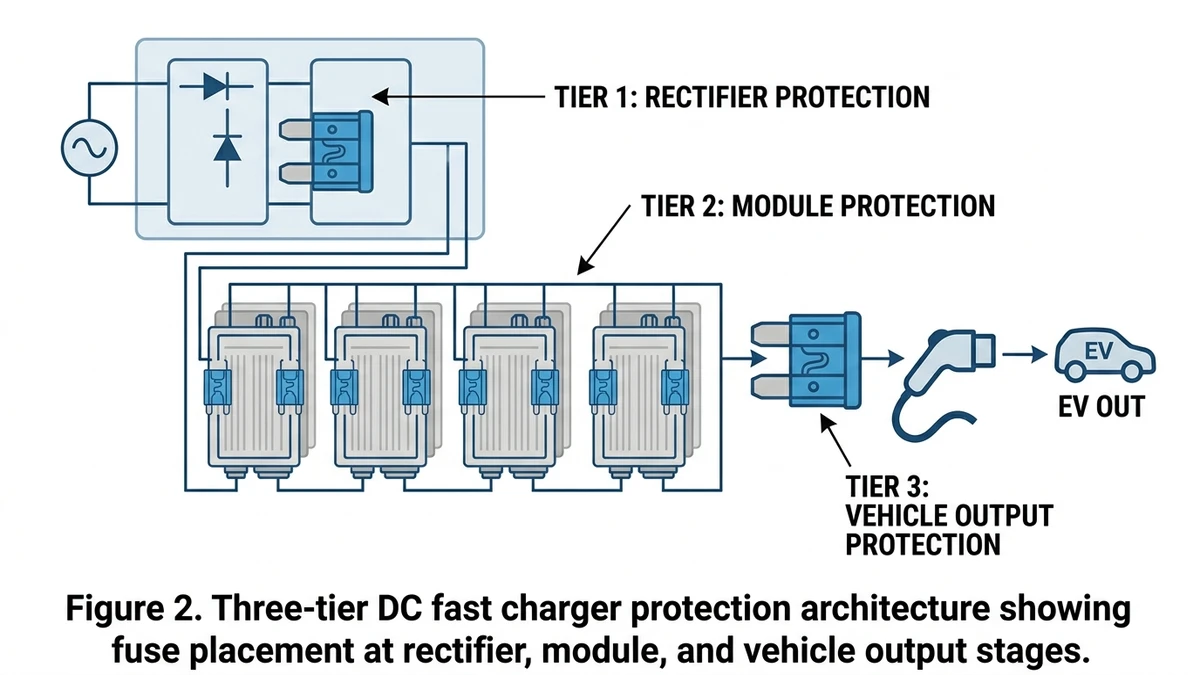
Once the fuse itself is correctly rated, the next question is placement within the charger so faults are isolated at the right point instead of taking down the full system.
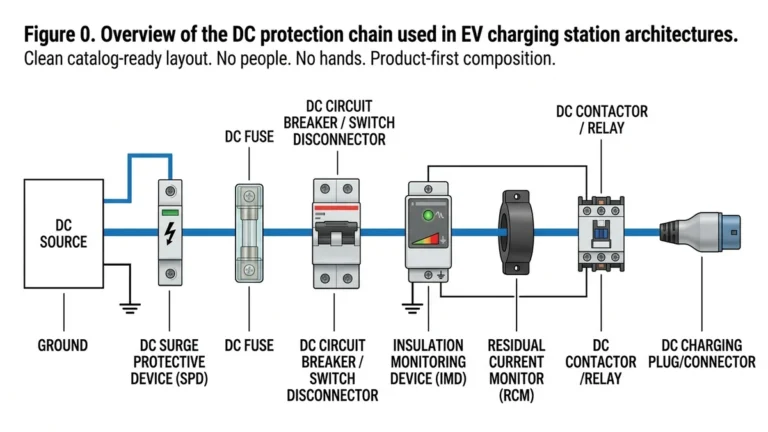
At the utility connection point, incoming AC power passes through surge protection devices and AC-side overcurrent protection before entering the rectifier. Once converted, the DC bus typically operates at 400–1000 VDC depending on charger topology. A high-rupturing-capacity DC fuse rated for the full prospective short-circuit current — commonly 20–50 kA in grid-tied installations — is placed immediately downstream of the rectifier output to protect the conversion stage from bus faults.
Each power module within the charger cabinet feeds a shared DC distribution bus. At this tier, individual module-level fuses, typically 200–630 A in gPV or gR classes, isolate a failed module without interrupting the entire charger. In a 120 kW fast charger with six 20 kW power modules, a single module fault cleared at Tier 2 keeps five modules online. A 60 MW EV charging hub project in Zhejiang Province (2024) reported that module-level fuse isolation reduced mean downtime per fault event from 4.2 hours to under 35 minutes.
The final tier protects the cable run between the charger output terminals and the vehicle inlet. Output fuses here are sized to the connector’s rated current — 200 A for CCS Combo 2 at 1000 VDC — and must clear faults without generating arc energy that could damage the connector housing. IEC 61851-23 governs DC EV supply equipment and sets requirements for output circuit protection response times at this stage.
For a broader view of how fuses integrate with disconnection and switching components across the full DC protection chain, the DC switch disconnector plays a complementary role at each tier boundary, enabling safe manual isolation during maintenance without breaking fault current.
[Expert Insight]
– Put module-level fuses as close as practical to the protected converter output to reduce unfused conductor length inside the cabinet.
– In multi-module chargers, review selectivity so a branch fault clears at Tier 2 before the main bus fuse sees enough let-through energy to open.
– Label tier-specific spare fuse ratings inside the cabinet door; field crews lose time when identical bodies carry different DC ratings.
After commissioning, long-term reliability is shaped less by catalog ratings than by altitude, temperature swing, contamination, and mechanical stress at the site.
In a 12 MW DC fast-charging corridor project in Qinghai Province (2023), maintenance crews found that fuses rated at sea-level conditions showed measurable derating at altitude — air density drops roughly 11% per 1,000 m, reducing convective cooling and shifting the fuse’s thermal equilibrium upward. Above 2,000 m, a conservative derating of 5–10% on continuous current rating is standard practice, though the exact factor depends on enclosure design and fuse body geometry.
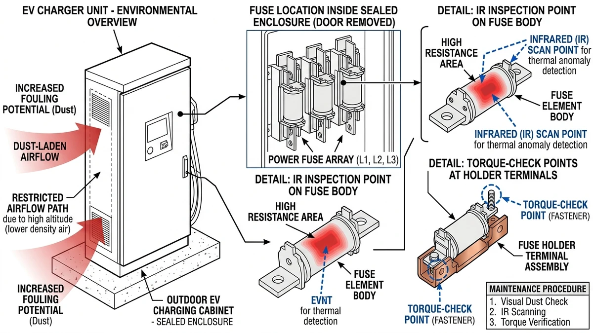
IEC 60269-1 governs general fuse performance, but altitude correction factors are often left to the manufacturer’s application notes rather than the core standard. Thermal cycling — daily swings of 40–60°C in outdoor EVSE enclosures — causes differential expansion between the fuse element and its ceramic body, gradually fatiguing the element. Inspection intervals of 12 months are commonly recommended for high-cycling environments; in desert or high-altitude sites, 6-month intervals are more appropriate.
EV charging stations near highways or rail corridors experience continuous low-frequency vibration, typically 5–50 Hz. Fuse holders with inadequate contact pressure can develop micro-arcing at the blade contacts, increasing contact resistance and creating localized heating that accelerates element aging. Torque specifications on fuse holder terminals — often 2.5–4 N·m depending on size — should be verified at installation and re-checked annually.
For sites combining high fault-current exposure with harsh environments, pairing fuses with a properly rated surge protection device helps manage transient overvoltage exposure at vulnerable outdoor charging locations.
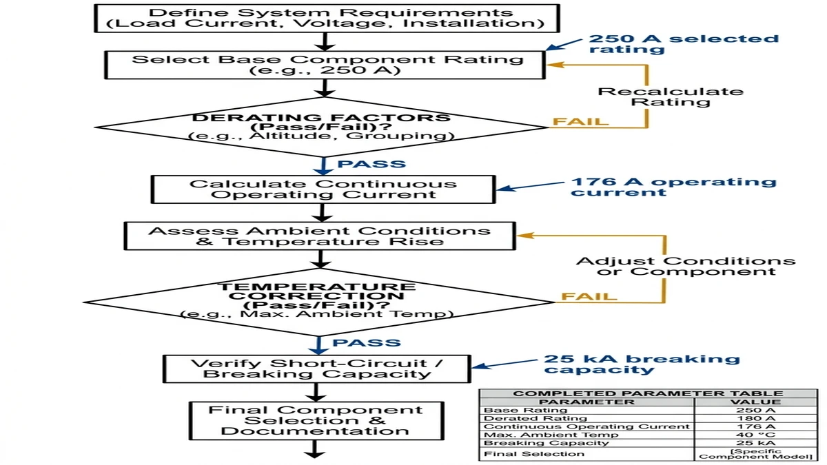
This example tracks the sequence engineers use to move from system data to a practical fuse rating.
Nominal bus voltage: 1000 VDC. Per IEC 60269-6, the fuse rated voltage must equal or exceed the maximum open-circuit voltage, including transient overshoot. Select a fuse rated at 1000 VDC minimum.
Maximum continuous current = P ÷ Vmin = 150,000 W ÷ 850 V = 176 A
Vmin represents the lowest expected bus voltage under full load. This is your baseline operating current.
Fuses must not operate above 80% of rated current under continuous load (IEC 60269-1, clause 8.3). Required fuse rating: 176 A ÷ 0.80 = 220 A minimum. Select the next standard size: 250 A.
Obtain PSCC from the upstream transformer or grid connection data. For a typical 250 kVA station transformer, PSCC at the DC busbar commonly reaches 15–25 kA. Confirm the fuse breaking capacity meets or exceeds this value.
The fuse’s pre-arcing I²t must be lower than the withstand I²t of the downstream cable and IGBT modules. Check manufacturer datasheets for both values at the operating temperature.
At 50°C ambient, apply a correction factor of approximately 0.90. Effective current capacity of a 250 A fuse drops to ~225 A — still above the 176 A operating current, so the selection holds.
Match the fuse to the available holder. For 250 A at 1000 VDC, a NH size 1 gPV fuse is a standard fit. Verify the holder’s voltage and current ratings independently.
Record all parameters in the table below. Cross-reference against the DC fuse product datasheet before procurement. For upstream coordination, also review the DC switch disconnector rating to ensure the full protection chain is aligned.
| Parámetro | Valor | Standard Reference |
|---|---|---|
| System voltage | 1000 VDC | IEC 60269-6 |
| Max operating current | 176 A | Calculated |
| Derating factor | 0.80 | IEC 60269-1 |
| Selected fuse rating | 250 A | Next standard size |
| Breaking capacity (min) | 25 kA | PSCC from transformer |
| Ambient correction (50°C) | ×0.90 | Manufacturer datasheet |
| Corrected capacity | 225 A | >176 A — pass |
| Form factor | NH Size 1 gPV | DIN 43620 |
In a 120 MW highway charging hub project in Zhejiang Province (2024), applying this derating and PSCC verification sequence prevented three fuse undersizing errors caught during design review.
Compliance choices affect procurement, approvals, and accepted test evidence, so the standard on the label needs to match the market where the charger will operate.
| Requisito | IEC Framework | UL Framework |
|---|---|---|
| Primary standard | IEC 60269-4 (semiconductor fuses, DC) | UL 248-15 (supplemental fuses) |
| EV-specific DC fuse standard | IEC 60269-6 (gPV/DC applications) | UL 2579 (high-voltage fuses for EVs) |
| Rated voltage range | Hasta 1500 VDC | Up to 1000 VDC (UL 248-15); 1500 VDC under UL 2579 |
| Capacidad de rotura | Typically 50–200 kA at rated voltage | 200 kA AC equivalent; DC derating applies |
| Temperature reference | 20°C ambient, correction factors per IEC 60269-1 | 25°C ambient per UL 248 series |
| Arc energy validation | Required at rated DC voltage × 1.1 | Required; test circuit L/R ≥ 15 ms |
| Regional applicability | EU, China, most of Asia-Pacific | North America; increasingly required for US EV OEMs |
| Certification body | DEKRA, TÜV, SGS | UL, CSA, Intertek |
| Marking requirement | Rated voltage, current, breaking capacity, gG/gPV class | Voltage, ampere rating, interrupting rating, UL Listed mark |
In practice, EV charging infrastructure projects in Europe and China typically mandate IEC 60269-6 compliance for DC-side fuses, with breaking capacity verified at the system’s prospective short-circuit current — commonly 25–50 kA in 400–800 VDC fast-charging architectures.
A 150 kW DC fast-charging corridor project in Zhejiang Province (2023) required fuses pre-qualified under both IEC 60269-4 and GB/T 13539, since the site operator supplied equipment to both domestic and export markets. Dual certification added roughly 6–8 weeks to the procurement timeline.
For North American deployments, UL 2579 is increasingly the baseline for EV high-voltage fuse qualification, particularly for OEM battery protection circuits operating above 800 VDC. Engineers sourcing DC fuses for cross-market projects should confirm whether the fuse carries both marks, or whether a single-standard part is acceptable under the local authority having jurisdiction.
With the technical requirements and compliance checks defined, final specification usually depends on matching four project inputs to a fuse family with demonstrated field margin.
Match your fuse to these minimums before specifying anything else:
In a 12-unit DC fast charging installation in Zhejiang Province (2023), undersized fuses rated at 500 VDC were installed in an 800 V bus system. Three units experienced fuse body cracking within 90 days due to sustained arc energy the housings were not designed to absorb. Replacing them with correctly rated 1000 VDC / 100 A gPV fuses resolved the failures entirely.
For a full range of DC fuses rated for EV and energy storage applications, the DC fuse product range covers 250–1500 VDC options with IEC 60269-6 compliance. If your project also requires string-level overcurrent protection or disconnection, the gPV fuse series and DC switch disconnectors are worth reviewing alongside your fuse selection.
AC fuses rely on current zero crossings to help extinguish the arc, while DC fault current can sustain the arc continuously. That makes high-voltage DC interruption a separate design problem requiring DC-rated fuse construction and testing.
Select a fuse with a rated DC voltage at or above the highest system voltage, including operating variation and transient margin. In many fast-charging systems, that means moving from 1000 VDC class to 1500 VDC class when the bus approaches the upper range.
The most common causes are thermal undersizing, poor derating for 50–60°C cabinet temperatures, and repetitive pulse loading during startup or dynamic charging cycles. Loose holder connections can also raise local heating and shorten fuse life.
Most DC fast chargers use layered protection rather than a single fuse. Separate fuse positions are often applied at the main bus, power module branches, and output side so one fault does not shut down the whole charger.
Higher elevation reduces air density and cooling effectiveness, which can push fuse temperature upward under the same current. Designers usually apply additional current derating above 2,000 m based on enclosure and manufacturer guidance.
A fuse that has operated should be replaced, even if the body appears intact from the outside. The internal element and arc-quenching structure are consumed during interruption and are not reusable.
Not always. IEC compliance is common in Europe and Asia-Pacific, while North American projects may require UL-marked products or dual-certified parts depending on the site and authority requirements.