Dirección
304 North Cardinal
Dorchester Center, MA 02124
Horas de trabajo
De lunes a viernes: de 7.00 a 19.00 horas
Fin de semana: 10.00 A 17.00 HORAS
Dirección
304 North Cardinal
Dorchester Center, MA 02124
Horas de trabajo
De lunes a viernes: de 7.00 a 19.00 horas
Fin de semana: 10.00 A 17.00 HORAS


Interrupción del circuito de CC representa uno de los problemas más desafiantes de la ingeniería eléctrica: interrumpir arcos de corriente continua que carecen de cruces por cero naturales. A diferencia de los sistemas de corriente alterna, en los que la corriente baja naturalmente a cero entre 100 y 120 veces por segundo, los arcos de corriente continua se mantienen indefinidamente a menos que los mecanismos de extinción forzada superen la conductividad del plasma ionizado.
Esta exploración técnica examina la física de la interrupción de circuitos de CC, desde la formación del plasma del arco y la dinámica de la energía hasta las sofisticadas tecnologías que permiten los modernos interruptores de CC: sistemas magnéticos de soplado, diseños de placas divisoras de arcos, novedosos medios de interrupción y métodos emergentes de interrupción de estado sólido.
Para los ingenieros de sistemas eléctricos, los diseñadores de equipos de protección y los investigadores que trabajan con transmisión HVDC, sistemas fotovoltaicos solares, almacenamiento en baterías o microrredes de CC, comprender los fundamentos de la extinción del arco es esencial para especificar la tecnología de corte adecuada y avanzar en los sistemas de interrupción de CC de próxima generación.
💡 Fundación Física: Un arco de CC es una descarga de plasma autosostenida con temperaturas que alcanzan los 6.000-20.000 K. Romper este arco requiere sistemas de ingeniería que enfríen rápidamente el plasma por debajo de su temperatura de ionización mientras se alarga el arco hasta que la caída de tensión supere la tensión de alimentación.
Cuando los contactos se separan bajo carga en un circuito de corriente continua, se forma un arco eléctrico, un canal de plasma conductor que tiende un puente sobre la separación. Este plasma presenta unas propiedades físicas únicas:
Distribución de la temperatura:
- Núcleo del arco: 15.000-20.000 K (más caliente que la superficie del sol)
- Arco límite: 6,000-8,000 K
- Interfaz ambiente: Rápido gradiente de temperatura hasta ~300 K
Propiedades eléctricas:
- Conductividad: 10²-10⁴ S/m (gama de semiconductores)
- Densidad de corriente: 10⁷-10⁹ A/m² en el punto catódico
- Gradiente de tensión: 20-100 V/cm en función de la magnitud de la corriente
Composición:
- Vapor de metal ionizado por erosión de contacto (Cu, Ag, W)
- Aire ionizado (moléculas de N₂, O₂ disociadas).
- Electrones libres (portadores primarios de corriente)
- Iones positivos (pesados, movilidad más lenta)
La tensión de arco de CC en estado estacionario sigue una relación empírica:
V_arco = V_cátodo + V_ánodo + E × l
Dónde:
- V_cátodo ≈ 10-15V (caída de tensión del cátodo)
- V_ánodo ≈ 5-10V (caída de tensión del ánodo)
- E = gradiente de la columna de arco (V/cm)
- l = longitud del arco (cm)
Gradiente del arco Dependencia de la corriente:
E(I) = A + B / I^n
Dónde:
- A, B, n = constantes en función del medio y de la presión
- Valores típicos en aire: A ≈ 20 V/cm, B ≈ 50 V-A^n/cm, n ≈ 0,5-0,7
Ejemplo de cálculo:
- Corriente: 1000A
- Longitud del arco: 5 cm
- E = 20 + 50 / 1000^0,6 = 20 + 1,25 = 21,25 V/cm
- V_arc = 15V + 10V + 21,25 × 5 = 131V
Para la extinción del arco, V_arc debe superar la tensión de alimentación V_system, forzando la corriente a cero.
La sostenibilidad del arco requiere que la entrada de energía equilibre las pérdidas:
Entrada de energía:
P_entrada = V_arco × I
Pérdidas de energía:
1. Radiación: P_rad ∝ T⁴ (Stefan-Boltzmann)
2. Convección: P_conv = h × A × (T_arc - T_ambient)
3. Conducción: P_cond a través de placas de arco
4. Calentamiento de electrodos: Energía absorbida en el cátodo/ánodo
Perspectiva crítica: La extinción del arco se produce cuando las pérdidas de energía superan a la entrada, lo que hace que la temperatura descienda por debajo del umbral de ionización (~5000 K para el aire).
La diferencia fundamental en la dificultad de rotura:
Arcos CA:
- La corriente cruza naturalmente el cero cada 8,3 ms (60 Hz) o 10 ms (50 Hz)
- El arco se apaga con corriente cero (sin aporte de energía)
- El disyuntor sólo debe impedir el reencendido durante 5-10 ms hasta que se invierta la polaridad.
- Recuperación dieléctrica: el medio recupera la capacidad aislante durante el paso por cero
Arcos de CC:
- Ningún arco cero de corriente natural se mantiene indefinidamente
- El aporte continuo de energía mantiene la temperatura del plasma
- La rotura requiere una reducción forzada de la corriente a cero
- Debe superar la tensión de alimentación continua intentando mantener el arco
- La recuperación dieléctrica debe producirse mientras la tensión es máxima
Comparación cuantitativa:
| Parámetro | CA (en el paso por cero) | CC (continua) |
|---|---|---|
| Entrada de energía del arco | 0 W (momentáneamente) | V_arc × I (continuo) |
| Tensión dieléctrica | Tensión de pico (1,41× RMS) | V_sistema continuo |
| Tiempo de recuperación | 5-10ms | Debe ser forzado |
| Dificultad de rotura | Línea de base (1×) | 3-10× más difícil |
⚠️ Desafío de ingeniería: Esta diferencia fundamental explica por qué los disyuntores de CA están clasificados entre 230 y 690 V CA, pero sólo entre 60 y 250 V CC: la ruptura de CC requiere separaciones de contacto 3-5 veces más largas y mecanismos de extinción de arco mejorados.

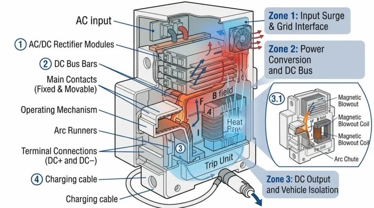
El soplado magnético aprovecha la fuerza de Lorentz que actúa sobre los conductores de corriente en campos magnéticos:
F = I × L × B
Dónde:
- F = vector fuerza (N)
- I = corriente de arco (A)
- L = vector de longitud de arco (m)
- B = vector de densidad de flujo magnético (T)
Magnitud de la fuerza:
F = I × L × B × sen(θ)
Para un soplado óptimo, θ = 90° (campo magnético perpendicular a la trayectoria del arco), dando:
F = I × L × B
Aceleración del arco:
El plasma del arco se comporta como un fluido con masa efectiva por unidad de longitud μ (kg/m):
a = F / (μ × L) = I × B / μ
Densidad másica típica del arco: μ ≈ 10-⁴ a 10-³ kg/m.
Ejemplo de cálculo:
- Corriente de arco: 1000A
- Longitud del arco: 0,02 m (2 cm)
- Campo magnético: 0,2T
- Densidad de la masa del arco: 5×10-⁴ kg/m
- Fuerza: F = 1000A × 0,02m × 0,2T = 4N
- Aceleración: a = 4N / (5×10-⁴ × 0,02) = 400.000 m/s².
Esta enorme aceleración impulsa el arco rápidamente hacia la canaleta del arco.
Diseño de imán permanente:
Los disyuntores de CC modernos utilizan imanes permanentes de NdFeB (Neodimio-Hierro-Borón) que proporcionan:
- Densidad de flujo: 0,1-0,3 Tesla en la región del arco
- No necesita alimentación externa
- Temperatura estable hasta 150°C (con grados de temperatura compensada)
- Diseño compacto
Campo generado por la bobina (bobina de soplado):
Para corrientes superiores (>1000A), las bobinas electromagnéticas generan campos más intensos:
B = (μ₀ × N × I) / l
Dónde:
- μ₀ = 4π × 10-⁷ H/m (permeabilidad del espacio libre).
- N = número de vueltas de la bobina
- I = corriente del interruptor (también corriente de arco)
- l = longitud efectiva de la trayectoria magnética
Ventaja de la autoenergía: Corriente de la bobina de soplado = corriente del interruptor, por lo que la fuerza magnética aumenta con la corriente de fallo, exactamente cuando se necesita el soplado más fuerte.
Configuración de la placa divisora:
Las tolvas de arco contienen entre 7 y 15 placas paralelas de acero o cerámica separadas entre sí 1-3 mm. Parámetros clave de diseño:
Distancia entre placas (d):
El espaciado óptimo equilibra requisitos contrapuestos:
- Demasiado estrecho (<1mm): Obstrucción con vapor metálico, flujo de gas restringido - Demasiado ancho (>3mm): Refrigeración del arco insuficiente, el arco puede desviar las placas.
- Óptimo: 1,5-2,5 mm para la mayoría de las aplicaciones de CC
Número de placas (n):
La tensión total del arco aumenta con las placas:
V_total ≈ n × (V_cátodo/ánodo + E_reducido × d)
Donde E_reducido es el gradiente de arco reducido entre placas (10-15 V/cm frente a 20-40 V/cm en aire libre).
Compromiso de diseño:
- Más placas → mayor tensión de arco → mejor extinción → disyuntor más grande y más caro.
- Menos placas → diseño compacto → puede fallar en la extinción de arcos de alta tensión.
Diseños típicos:
| Tensión nominal | Número de placas | Espacio entre placas | Tensión total del arco |
|---|---|---|---|
| 125 V CC | 5-7 | 2 mm | 150-200V |
| 250 V CC | 7-9 | 2 mm | 250-350V |
| 600 V CC | 9-12 | 2 mm | 600-800V |
| 1000 V CC | 12-15 | 2,5 mm | 1000-1400V |
Selección de materiales:
- Chapas de acero: Bajo coste, buenas propiedades magnéticas (mejora el soplado), capacidad térmica adecuada
- Acero revestido de cobre: Conductividad mejorada, reduce la caída de tensión a través del vertedero
- Placas de cerámica: Resistencia térmica superior, utilizada en aplicaciones de servicio extremo
Movimiento de arco trifásico:
1. Formación inicial (0-2ms):
- Formación de arcos en los contactos de separación
- La fuerza de Lorentz comienza a acelerar los puntos de la raíz del arco
- Longitud del arco: sólo distancia entre contactos (2-10 mm)
2. Fase de elongación (2-10ms):
- Raíz de arco impulsada hacia arriba por el campo magnético
- La longitud del arco aumenta exponencialmente
- El arco entra en las placas inferiores del conducto de arco
- La tensión del arco empieza a subir
3. Fase de división (10-50ms):
- El arco entra en contacto con la primera placa divisora
- El arco se divide en dos series
- El proceso se repite en cada placa sucesiva
- Tensión total del arco: suma de todos los segmentos individuales del arco
- Una vez V_arc > V_sistema, corriente forzada a cero
Velocidad del arco:
Las mediciones experimentales muestran la velocidad de la raíz del arco:
v = (I × B) / (ρ × C_p × ΔT)
Dónde:
- ρ = densidad del plasma (~10-⁴ kg/m³)
- C_p = capacidad calorífica específica
- ΔT = diferencia de temperatura (del arco al ambiente).
Velocidades típicas: 50-200 m/s para corrientes 100-5000A.

Principio de funcionamiento:
Los disyuntores de vacío interrumpen la corriente en un entorno próximo al vacío (10-⁴ a 10-⁶ Torr):
- No hay moléculas de gas que ionizar → el arco no puede mantenerse
- El vapor metálico de los contactos es la única fuente de ionización
- El vapor se condensa rápidamente en superficies frías → desionización rápida.
Retos de la rotura del vacío de CC:
A diferencia de los rompedores de vacío de CA (tecnología madura), los rompedores de vacío de CC se enfrentan a problemas únicos:
Problema 1 - Arco de vapor metálico sostenido:
- El arco de CC vaporiza continuamente el material de contacto
- Sin corriente cero para interrumpir la producción de vapor
- La presión del vapor se acumula, reduciendo la calidad del vacío
Solución: Apertura de contacto a alta velocidad (3-5 m/s) y grandes superficies de condensación de vapor.
Problema 2 - Reencendido:
- Después de la extinción del arco, la tensión continua completa a través del hueco inmediatamente
- Un solo ion puede provocar la reignición
- Requiere una recuperación dieléctrica superior
Solución: Contactos de campo magnético axial (AMF) que difunden el arco, reduciendo la concentración de vapor.
Rendimiento de los disyuntores de vacío de CC:
| Parámetro | Interruptor de vacío CA | Disyuntor de vacío CC |
|---|---|---|
| Tensión nominal | Hasta 40,5 kV CA | Hasta 3 kV CC (límite práctico) |
| Capacidad de rotura | 63-100 kA | 20-40 kA |
| Vida eléctrica | Más de 30.000 operaciones | 10.000-15.000 operaciones |
| Contacto Erosión | 0,01-0,05 mm por 10.000 operaciones | 0,1-0,3 mm por 10.000 operaciones |
Aplicaciones: Los disyuntores de vacío de CC destacan en la gama de 500-3000 V CC: sistemas de tracción, almacenamiento de energía en baterías, distribución de CC de media tensión.
Propiedades del hexafluoruro de azufre:
El gas SF₆ ofrece propiedades dieléctricas y de apagado del arco superiores:
- Rigidez dieléctrica2-3× aire a la misma presión
- Electronegatividad: Captura electrones libres → desionización rápida.
- Conductividad térmica: Excelente refrigeración del arco
- Estabilidad química: No inflamable, no tóxico (aunque potente gas de efecto invernadero)
DC rompe con SF₆:
Gradiente de tensión de arco en SF₆:
E_SF6 ≈ (1/2) × E_air a la misma presión
Un gradiente de tensión más bajo significa que se necesita un arco más largo para un V_arc equivalente, pero una recuperación dieléctrica superior lo compensa.
Interruptores SF₆ de tipo buffer:
El pistón mecánico comprime el SF₆ durante la apertura, expulsando gas a alta presión a través del arco:
- Presión: 5-15 bar durante el soplado
- Velocidad del gas: 100-300 m/s
- Potencia de refrigeración: Elimina entre 10 y 50 MW de energía del arco en milisegundos.
Limitaciones de los interruptores SF₆ de CC:
- Medio ambiente: SF₆ tiene un GWP (potencial de calentamiento global) = 23.500
- Fugas: Requiere construcción sellada y supervisión
- Coste: La manipulación y contención de SF₆ añade 30-50% al coste del disyuntor
- Normativa: Eliminación progresiva en la UE para aplicaciones de media tensión
Gases alternativos:
Investigación de alternativas al SF₆:
- C₄F₇N (Fluoronitrilo): 99% menor GWP, rigidez dieléctrica similar
- Mezclas de CO₂ / O₂.: Cero GWP, requiere mayor presión (20-30 bar)
- Vacío + gas tampón: Tecnología híbrida en desarrollo
Interrupción basada en la electrónica de potencia:
Los disyuntores de CC de estado sólido (SSCB) utilizan interruptores semiconductores:
- IGBTs (Transistores bipolares de puerta aislada): Hasta 6,5 kV, 6 kA
- IGCTs (Tiristores integrados conmutados por puerta): Hasta 6 kV, 6 kA
- MOSFET de SiC: Emergente, conmutación más rápida, menores pérdidas
Principio de funcionamiento:
1. Fallo detectado por sensores de corriente
2. La señal de puerta apaga el semiconductor (microsegundos)
3. La corriente conmuta en paralelo al MOV (Varistor de óxido metálico)
4. El MOV absorbe energía: E = ½ L I² (energía almacenada en la inductancia del sistema)
5. Pinzas de tensión del sistema a tensión MOV
6. La corriente decae hasta cero al disiparse la energía
Ventajas de la SSCB:
✅ Interrupción ultrarrápida: 1-5 microsegundos (frente a los 20-50 ms mecánicos)
✅ Sin desgaste por contacto ni erosión.
✅ Funcionamiento silencioso, sin arco eléctrico
✅ Vida mecánica ilimitada
✅ Puede interrumpir a cualquier nivel de corriente (no está limitado por el mantenimiento mínimo del arco).
✅ Capacidad de reconexión rápida (μs frente a segundos para la mecánica).
Limitaciones del SSCB:
❌ Mayores pérdidas por conducción (1-3 V de caída hacia delante frente a <0,1 V de los contactos mecánicos) ❌ Caro: 5-10 veces el coste de un disyuntor mecánico equivalente ❌ Problemas de disipación de calor (20-50 W por kA continuo) ❌ Valores nominales de tensión limitados por el apilamiento en serie de dispositivos ❌ Capacidad de absorción de energía limitada por el tamaño/coste del MOV
Dominios de aplicación:
- Transmisión HVDC: Interconexiones de red que requieren aislamiento de fallos en <5 ms - Centros de datos: Cargas críticas que requieren protección subciclo
- Vehículos eléctricos: Desconexión de la batería con funcionamiento sin arco
- Energías renovables: Aislamiento rápido de fallos de CC en parques solares y eólicos
Interruptores híbridos:
Combina mecánica y estado sólido:
- Funcionamiento normal: Contactos mecánicos (baja pérdida)
- Detección de fallos: La corriente conmuta al SSCB paralelo
- Interrupciones SSCB en μs
- Los contactos mecánicos se abren tras la conmutación sin arco eléctrico
- Lo mejor de ambos: bajas pérdidas + rotura rápida
Coste: 2-3× rompedor mecánico (frente a 5-10× SSCB puro).

Configuración del circuito de prueba:
Las pruebas de capacidad de ruptura en CC requieren instalaciones de prueba especializadas de alta potencia:
Componentes:
- Fuente de alimentación de CC: Alimentación de CA rectificada o bancos de baterías (escala MW)
- Inductancia en serie: L = 50-500mH (simula la inductancia de línea)
- Resistencia paralela: R determina la constante de tiempo L/R
- Interruptor de prueba: Dispositivo bajo prueba (DUT)
- Resistencia a la carga: Disipa la energía tras la interrupción
Corriente de prueba:
I_test = V_test / R_total en estado estacionario
I_fallo = V_prueba × √(C/L) pico transitorio (con capacitancia)
Secuencia de pruebas:
1. Verificación previa a la prueba: Mida la resistencia de contacto (1 GΩ).
2. Acondicionamiento térmico: Pasa la corriente nominal durante 1 hora, alcanza el equilibrio térmico
3. Prueba de rotura: Aplica la corriente de prueba, activa la apertura del disyuntor
4. Medición: Registrar la tensión del arco, la duración del arco y la absorción de energía.
5. Inspección posterior a la prueba: Examinar la erosión de los contactos, los daños en el conducto del arco, la integridad del aislamiento
Criterios de aceptación:
✓ La corriente se interrumpe en el tiempo especificado (normalmente <100 ms) ✓ La tensión del arco permanece estable (sin reignición) ✓ El hueco de contacto resiste la tensión de recuperación (2× nominal + 1000 V durante 1 minuto) ✓ No se produce incendio, explosión ni rotura de la carcasa ✓ El interruptor puede realizar 3 operaciones de corte consecutivas a la capacidad nominal
Energía disipada en el arco:
E_arc = ∫ V_arc(t) × I(t) dt
Integrado sobre la duración de la interrupción (separación de contactos a cero de corriente).
Valores típicos:
| Sistema | Tensión | Actual | Duración del arco | Energía del Arco |
|---|---|---|---|---|
| Energía solar residencial | 600V | 200A | 30 ms | 3,6 kJ |
| Solar comercial | 1000V | 1000A | 40ms | 40 kJ |
| Sistema de baterías | 500V | 5000A | 25ms | 62,5 kJ |
| Circuito HVDC | 10kV | 10kA | 50 ms | 5 MJ |
Lugares de absorción de energía:
- Placas del vertedero de arco: 40-60% (masa térmica)
- Radiación de arco de plasma: 20-30% (luz, calor)
- Contacto erosión: 10-15% (vaporización de metales)
- Calefacción/expansión de gas: 5-10%
Tasa de erosión:
Pérdida de masa por operación de rotura:
Δm = k × Q
Dónde:
- Q = carga eléctrica transferida: Q = ∫ I(t) dt (culombios)
- k = constante de erosión (mg/kA-s, dependiente del material)
Constantes de erosión típicas:
| Material de contacto | k (mg/kA-s) | Coste relativo | Aplicación típica |
|---|---|---|---|
| Cobre (Cu) | 50-80 | 1× | Poco trabajo, sensible a los costes |
| Plata-tungsteno (AgW10) | 10-20 | 5× | Carga media, solar fotovoltaica |
| Óxido de plata y estaño (AgSnO₂) | 5-10 | 8× | Alto rendimiento, larga vida útil |
| Carburo de wolframio (WC) | 2-5 | 15× | Uso extremo, aeroespacial |
Cálculo de la vida útil eléctrica:
N_operaciones = M_contacto / Δm
Donde M_contacto es la masa inicial del material de contacto.
Ejemplo:
- Material de contacto: AgW10, k = 15 mg/kA-s
- Corriente de corte: 200 A (0,2 kA)
- Duración del arco: 30 ms (0,03 s)
- Carga: Q = 0,2 kA × 0,03s = 0,006 kA-s
- Erosión por operación: Δm = 15 × 0,006 = 0,09 mg
- Masa de contacto: 500 mg
- Vida útil prevista: N = 500 / 0,09 = 5.556 operaciones

Principio:
Inyecte un impulso de corriente inversa para forzar la corriente continua a través del cero, imitando el cruce por cero de la corriente alterna:
1. Funcionamiento normal: La corriente continua fluye a través del disyuntor
2. Detección de fallos: Secuencia de ruptura del gatillo
3. Descarga del condensador: El condensador precargado descarga la corriente inversa a través del disyuntor
4. Cero actual: Corriente de defecto directa + corriente inversa del condensador = 0 momentáneamente
5. El disyuntor se abre: En el paso por cero, las técnicas convencionales de corte de CA funcionan
6. Extinción del arco: Ocurre en el cero actual, muy simplificado
Configuración del circuito:
Fuente CC --[L]--[Interruptor]--[Carga]
                 |
             [C]--[Interruptor]
             (precargado a -V)
Cuando el interruptor se cierra, el condensador se descarga: I_cap = (V_cap / Z) × sen(ωt)
Donde Z = √(L/C), ω = 1 / √(LC)
Ventajas:
✓ Permite utilizar la tecnología de ruptura de CA probada para CC.
✓ Reduce considerablemente la erosión por contacto
✓ Interrupción más rápida que la ruptura de CC pura.
✓ Menor coste que las soluciones de estado sólido
Desafíos:
❌ Requiere almacenamiento de energía (batería de condensadores).
❌ Cronometraje crítico (precisión de μs)
❌ Número limitado de operaciones (vida útil del condensador).
❌ El condensador debe soportar toda la tensión del sistema
Estado de desarrollo: Fase de prototipo, prometedora para aplicaciones de 1-10 kV CC.
Concepto:
Los materiales superconductores tienen una resistencia nula en estado normal y pasan a estado resistivo en caso de fallo:
1. Funcionamiento normal: SFCL en estado superconductor (R = 0)
2. Se produce un fallo: Un pico de corriente calienta un superconductor por encima de la temperatura crítica
3. Quench: El superconductor se vuelve resistivo (R = 1-10 Ω)
4. Limitación actual: Corriente de defecto limitada por la resistencia SFCL
5. Funcionamiento del interruptor: El disyuntor convencional interrumpe la corriente limitada (mucho más fácil)
Ventajas:
✓ Automático, sin circuito de detección
✓ Respuesta extremadamente rápida (<1ms) ✓ Reduce el esfuerzo de corte de los interruptores aguas abajo ✓ Autorrecuperación tras la eliminación del fallo
Desafíos:
❌ Requiere refrigeración criogénica (-196°C para YBCO, -269°C para NbTi).
❌ Coste muy elevado ($$$$$)
❌ La energía absorbida en el SFCL durante el enfriamiento puede dañar el conductor.
❌ Tiempo de recuperación: 1-10 segundos
Aplicaciones: Redes HVDC, infraestructuras críticas, instalaciones de investigación.
Estaciones convertidoras HVDC:
Los convertidores HVDC basados en MMC constan de cientos de submódulos (SM), cada uno de los cuales contiene:
- Semiconductores de potencia (IGBT)
- Almacenamiento de energía mediante condensadores
- Interruptor de derivación
Capacidad de rotura intrínseca:
Al controlar la inserción/eliminación de SM, MMC puede:
1. Detectar fallo CC: Sensores de corriente en el lado de CC
2. Convertidor de bloques: Apaga todos los IGBT (bloquea la energía del lado de CA)
3. Descarga lado CC: Inserte condensadores SM en serie con el fallo de CC
4. Absorber energía: Los condensadores SM absorben la energía de la avería: E = ½ C V²
5. Decaimiento actual: La corriente continua decae al disiparse la energía
Ventajas:
✓ Sin equipo de frenado adicional (inherente al convertidor).
✓ Muy rápido: 2-5ms
✓ Puede eliminar averías de forma autónoma
✓ Permite la autorreparación de la red de CC
Limitaciones:
❌ Solo funciona para sistemas interconectados con convertidores (no redes de CC puras).
❌ Absorción de energía limitada por el tamaño del condensador SM.
❌ Pérdida temporal del control del convertidor durante la eliminación del fallo.
Estado: Operativo en proyectos HVDC modernos (North Sea Wind Power Hub, China ±500 kV DC grid).

Los interruptores de CA dependen de los pasos por cero naturales de la corriente cada 8-10 ms, en los que el arco se extingue de forma natural. La CC no tiene cruces por cero, el arco se mantiene indefinidamente. Los interruptores de CA carecen de: (1) separaciones de contacto suficientes (2× a 3× más anchas necesarias para CC), (2) conductos de arco mejorados con soplado magnético, (3) materiales resistentes al arco continuo. El uso de interruptores de CA para CC provoca un fallo catastrófico: los contactos se sueldan, el arco se mantiene hasta que se rompe la carcasa y hay riesgo de incendio. La física fundamental del mantenimiento del arco de CC requiere una tecnología de ruptura especialmente diseñada.
Por debajo de cierto umbral de corriente (~0,5-2A para los arcos de aire), la insuficiente entrada de energía mantiene la temperatura del plasma por encima del punto de ionización. El arco se extingue espontáneamente cuando las pérdidas por enfriamiento superan el aporte. Esta corriente de arco mínima I_min sigue: I_min ≈ √(P_loss / R_arc) donde P_loss son las pérdidas por radiación + convección, R_arc es la resistencia del arco. Para una interrupción de corriente muy baja (<1A), el arco puede extinguirse durante la separación de los contactos sin mecanismos especiales. Esta es la razón por la que los disyuntores de CC pueden interrumpir sobrecargas fácilmente, pero requieren una tecnología sofisticada para cortocircuitos de alta corriente.
El material de contacto determina: (1) la tensión del arco: los metales con alta función de trabajo (W, Mo) producen mayores caídas de tensión en el cátodo, lo que favorece la extinción; (2) la velocidad de erosión: los metales refractarios (W, AgW) se erosionan más lentamente, lo que mantiene la integridad del contacto; (3) la presión de vapor: una presión de vapor baja reduce la densidad del plasma, lo que favorece la desionización. Plata-tungsteno (AgW) es el equilibrio óptimo: la plata proporciona conductividad (baja caída de tensión en estado cerrado), el tungsteno proporciona resistencia al arco (alto punto de fusión 3422°C frente a la plata 962°C). El cobre puro se erosiona entre 5 y 10 veces más rápido que el AgW, por lo que no es adecuado para operaciones de rotura frecuentes.
Un espaciado más estrecho aumenta la eficacia de la división del arco (más divisiones), pero se corre el riesgo de que se obstruya el vapor metálico y se reduzca el caudal de gas. Una separación mayor mejora la refrigeración pero reduce las divisiones. La separación óptima d = 1,5-2,5 mm equilibra estos factores. Para la tensión nominal V, número necesario de placas: n ≈ V / (15V + E × d) donde E ≈ 10-15 V/cm entre placas. Ejemplo: interruptor de 1000V con separación de 2mm: n = 1000 / (15 + 12,5 × 0,2) = 1000 / 17,5 ≈ 57 → Utilizar 12-15 placas (multiplicación del arco en serie).
Los SSCB utilizan dispositivos semiconductores (IGBT, MOSFET) con caídas de tensión de 1 a 3 V en comparación con contactos mecánicos de <0,1 V. Con una corriente continua de 1.000 A: pérdida por contacto mecánico = 0,05 V × 1.000 A = 50 W, pérdida por IGBT = 2 V × 1.000 A = 2.000 W (40 veces más). Este calor debe disiparse mediante disipadores, lo que aumenta el tamaño y el coste. Los semiconductores de banda ancha (SiC, GaN) mejoran las pérdidas, pero siguen siendo entre 5 y 10 veces superiores a las mecánicas. Por eso, los interruptores híbridos utilizan contactos mecánicos para el funcionamiento normal y sólo cambian a estado sólido en caso de fallo.
La tensión nominal sin CC suele ser 15-30% de la tensión nominal de CA para el mismo interruptor en vacío. Ejemplo: un interruptor en vacío de CA de 12 kV sólo puede tener una tensión nominal de CC de 1,5-3 kV. Razones: (1) el arco de CC produce vapor metálico continuo (sin recuperación del paso por cero), (2) tensión de CC completa en el hueco inmediatamente después de la extinción del arco (frente a la acumulación gradual de tensión de CA), (3) un único evento de reignición provoca el fallo en cascada (la CA tiene otro paso por cero). Los disyuntores de vacío de CC requieren una mayor velocidad de apertura de los contactos (3-5 m/s frente a 1-2 m/s para CA) y contactos AMF (campo magnético axial) especiales para difundir el arco.
El SF₆ tiene un potencial de calentamiento global (PCG) de 23.500 (CO₂ = 1), que dura 3.200 años en la atmósfera. Una fuga de kg de SF₆ equivale a emisiones de 23,5 toneladas métricas de CO₂. El Reglamento de gases fluorados de la UE restringe el uso de SF₆ en equipos nuevos <52kV a partir de 2026. Alternativas en desarrollo: (1) Fluoronitrilo (C₄F₇N) - GWP <1, rigidez dieléctrica similar, (2) Mezclas de CO₂ - GWP 1, requiere mayor presión, (3) Tecnología de vacío - cero emisiones, tensión limitada. Para las nuevas instalaciones de CC <10 kV, se prefiere la tecnología de ruptura de aire o de vacío al SF₆ por motivos de sostenibilidad medioambiental.
El corte de circuitos de corriente continua representa la intersección de la física del plasma, la teoría del campo electromagnético, la ciencia de los materiales y la electrónica de potencia. Desde el reto fundamental de extinguir arcos autosostenidos hasta soluciones sofisticadas que emplean sistemas magnéticos de soplado, tecnología de vacío y enfoques emergentes de estado sólido, el corte de CC moderno hace posible la infraestructura eléctrica de las energías renovables, el transporte eléctrico y la distribución de energía de CC.
Principios técnicos fundamentales:
Física del arco: Los arcos de CC se mantienen a 15.000-20.000 K con un gradiente de tensión de 20-100 V/cm. La extinción requiere forzar V_arc > V_system mediante el alargamiento, enfriamiento o división del arco. El equilibrio energético determina la sostenibilidad del arco: cuando las pérdidas (radiación, convección, conducción) superan la entrada (V_arc × I), se produce la desionización.
Explosión magnética: La fuerza de Lorentz F = I × L × B acelera el arco hacia los conductos de la placa divisora a 50-200 m/s. Los imanes permanentes (0,1-0,3T) o las bobinas de soplado proporcionan un campo perpendicular a la trayectoria del arco. Las bobinas autoalimentadas aumentan ventajosamente la intensidad de campo con la corriente de defecto.
Espectro tecnológico: Los interruptores de corte en aire dominan las aplicaciones 10 kV pero se enfrenta a la eliminación progresiva medioambiental. Los interruptores de estado sólido ofrecen una interrupción ultrarrápida (μs) para aplicaciones críticas a pesar de un sobrecoste de 5-10 veces.
Trayectoria futura: Los semiconductores de banda ancha (SiC, GaN) permitirán SSCB de mayor voltaje y menores pérdidas. Los diseños híbridos mecánica-estado sólido equilibrarán rendimiento y coste. Las técnicas de corriente artificial cero pueden revolucionar los interruptores de CC de media tensión. La infraestructura de la red de CC exigirá una innovación en los interruptores que iguale los 150 años de desarrollo de los interruptores de CA.
Para los ingenieros que especifican equipos de protección de CC, la comprensión de la física de la extinción del arco informa la selección de la tecnología adecuada. Para los investigadores que desarrollan la tecnología de los sistemas de potencia, la ruptura de CC sigue siendo un campo fértil con retos fundamentales que impulsan la innovación en materiales, magnetismo y electrónica de potencia.
Recursos técnicos relacionados:
- Tecnología de disyuntores de CC - Vista general completa del sistema de disyuntores
- Interruptor-seccionador de CC Ingeniería - Tecnología de aislamiento manual
- Coordinación de protección de CC - Diseño de la protección del sistema
Colaboración en la investigación: SYNODE colabora con universidades e instituciones de investigación en tecnología avanzada de interrupción de CC. Póngase en contacto con nuestra división de I+D para asociaciones académicas, acceso a instalaciones de prueba o consultas sobre licencias de tecnología.
Última actualización: Octubre de 2025
Autor: Grupo SYNODE de Tecnología Avanzada
Revisión técnica: Doctores en Ingeniería Eléctrica, Miembros Senior del IEEE
Referencias: CEI 62271-100:2021, Norma IEEE C37.100:2023, Folleto técnico 683 del CIGRE