Adresse
304 North Cardinal
St. Dorchester Center, MA 02124
Heures de travail
Du lundi au vendredi : de 7h00 à 19h00
Le week-end : 10H00 - 17H00
Adresse
304 North Cardinal
St. Dorchester Center, MA 02124
Heures de travail
Du lundi au vendredi : de 7h00 à 19h00
Le week-end : 10H00 - 17H00


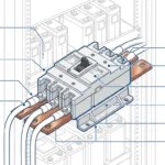
A DC circuit breaker box serves as the protective housing that transforms individual breakers into a safe, organized, and code-compliant distribution system. Far more than just a metal box, the enclosure determines system reliability, safety, and longevity through environmental protection, thermal management, and proper component spacing.
This comprehensive guide covers enclosure selection criteria, NEMA/IP rating interpretation, thermal design considerations, and professional installation techniques for DC breaker boxes in solar, marine, and industrial applications.
The breaker box enclosure protects critical electrical components from:
Environmental Hazards:
– Moisture and humidity (condensation, rain, spray)
– Dust and particulates (desert, industrial, construction sites)
– Corrosive atmospheres (marine salt spray, chemical plants)
– UV radiation (outdoor installations)
– Physical impact (accidental contact, tool drops)
– Vermin and insects (nesting, chewing)
Operational Hazards:
– Arc flash containment (prevents external fire spread)
– Accidental contact with live terminals (shock protection)
– Electromagnetic interference (EMI shielding)
– Thermal stress (heat buildup from high current)
Regulatory Requirements:
– NEC Article 312: Cabinet and Cutout Box requirements
– NEC Article 110.26: Working clearances
– OSHA 1910.303: Electrical enclosure standards
– UL 50: Enclosure standards for electrical equipment
– IEC 60529: IP rating system
Common Applications:
– Residential solar PV systems (5-15kW)
– Commercial solar arrays (50-200kW)
– Marine vessel electrical distribution
– RV and mobile power systems
– Off-grid battery storage
– Telecommunications backup power
– Industrial DC machinery
The National Electrical Manufacturers Association (NEMA) rating system defines enclosure protection levels for various environments:
#### NEMA 1: General Purpose Indoor
Protection Level:
– Light dust and incidental contact
– Indoor use only, dry locations
– No water or corrosion protection
Construction:
– Cold-rolled steel, powder-coated
– Simple door latch or screw closure
– Ventilation holes typical
– No gasket seal
Typical Applications:
– Indoor residential solar disconnect
– Climate-controlled equipment rooms
– Office building electrical closets
Limites :
– Will rust if moisture present
– Dust penetration through ventilation
– Not suitable for garages, basements with humidity
Cost Factor: Budget tier ($50-150 for 12×16″ box)
#### NEMA 3R: Outdoor Rainproof
Protection Level:
– Rain, snow, sleet (falling water)
– Ice formation (external)
– Windblown dust (limited)
Construction:
– Galvanized or powder-coated steel
– Drip shield over door
– Gasket seal on door perimeter
– Drainage channels at bottom
– Ventilated or non-ventilated options
Typical Applications:
– Rooftop solar disconnect boxes
– Outdoor DC combiner boxes
– Residential solar inverter enclosures
– RV exterior electrical panels
Limites :
– Not waterproof (water can enter from below during flooding)
– Not dust-tight (fine dust can penetrate)
– Limited corrosion resistance (not for marine)
Cost Factor: Mid-range ($120-300 for 12×16″ box)
#### NEMA 4/4X: Waterproof and Corrosion-Resistant
Protection Level:
– Direct water spray from any direction
– Splashing water and waves
– Wind-driven rain
– Hose-directed water
– Ice formation (external and internal)
– Corrosion resistance (4X only)
Construction:
– NEMA 4: Powder-coated steel or aluminum
– NEMA 4X: 304 or 316 stainless steel, fiberglass, polycarbonate
– Continuous gasket seal (closed-cell foam)
– Compression latches or cam locks
– Cable glands with O-ring seals
– No ventilation (sealed design)
Typical Applications:
– Marine vessel breaker panels
– Waterfront solar installations
– Industrial washdown areas
– Offshore platforms
– Agricultural equipment
Limites :
– Heat buildup in sealed enclosures (requires thermal management)
– Higher cost for 4X stainless construction
– Heavier weight
Cost Factor: Premium tier ($300-800 for 12×16″ box, NEMA 4X)
#### NEMA 12: Industrial Dust-Tight
Protection Level:
– Settling dust and airborne fibers
– Lint and flyings
– Light splashing or seepage of water and coolants
– Indoor only
Construction:
– Continuous gasket seal
– Oil-resistant gaskets
– No external mounting holes (threaded inserts inside)
Typical Applications:
– Industrial facilities with dust
– Woodworking shops
– Textile mills
– Indoor solar equipment rooms with HVAC filtration
Cost Factor: Mid-premium ($200-400 for 12×16″ box)
IP (Ingress Protection) ratings consist of two digits: IPXY
First Digit (X) – Solid Particle Protection:
| Evaluation | Protection Level | Description |
|---|---|---|
| 0 | No protection | Open enclosure |
| 1 | >50mm objects | Hand-sized objects |
| 2 | >12.5mm objects | Finger-sized objects |
| 3 | >2.5mm objects | Tool-sized objects |
| 4 | >1mm objects | Wire-sized objects |
| 5 | Dust protected | Limited ingress (no harmful deposit) |
| 6 | Etanche à la poussière | No dust ingress whatsoever |
Second Digit (Y) – Liquid Protection:
| Evaluation | Protection Level | Description |
|---|---|---|
| 0 | No protection | Open enclosure |
| 1 | Vertical drips | Condensation protection |
| 2 | 15° drips | Tilted up to 15° |
| 3 | Spraying water | 60° from vertical |
| 4 | Éclaboussures d'eau | Any direction |
| 5 | Jets d'eau | 6.3mm nozzle |
| 6 | Powerful jets | 12.5mm nozzle |
| 7 | Temporary immersion | 1m depth, 30 minutes |
| 8 | Continuous immersion | >1m depth, continuous |
Common Equivalencies:
– NEMA 1 ≈ IP20 (indoor, basic protection)
– NEMA 3R ≈ IP54 (outdoor, rain-protected)
– NEMA 4 ≈ IP65 (waterproof, dust-protected)
– NEMA 4X ≈ IP66 (waterproof, dust-tight, corrosion-resistant)
– Marine grade ≈ IP67 (submersion-resistant)
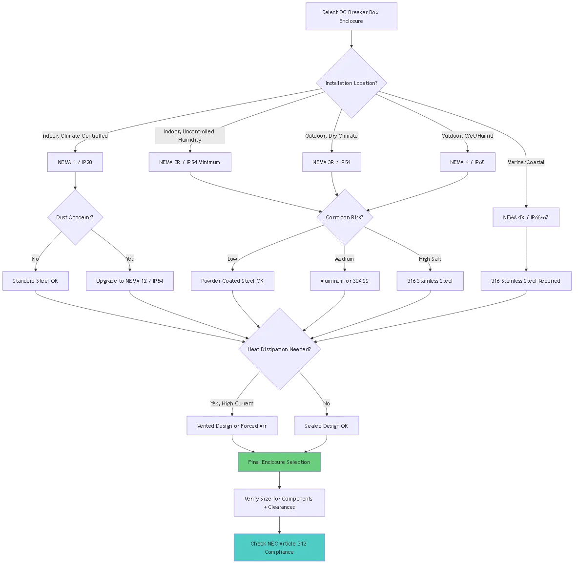
Step 1: Inventory Components
Create a list of all components to be mounted inside the enclosure:
Example Solar System DC Breaker Box:
- Main disconnect breaker: 200A (4"W × 6"H × 3"D)
- Inverter breaker: 100A (3"W × 4"H × 3"D)
- Charge controller breaker: 60A (3"W × 4"H × 3"D)
- 4× Load circuit breakers: 20A each (2"W × 3"H × 2"D each)
- Positive busbar: 12"L × 2"W × 1"H
- Negative busbar: 12"L × 2"W × 1"H
- Ground busbar: 12"L × 1"W × 0.5"H
- Surge protector (optional): 4"W × 6"H × 3"D
Step 2: Calculate Component Footprint
Total width requirement:
- Breakers in single row: 4" + 3" + 3" + (4 × 2") = 18"
- Allow 2" spacing between components: + 10" = 28"
Total height requirement: – Busbars + breakers + wire bending space: – Busbars: 3″ (height with standoffs) – Breakers: 6″ (tallest breaker) – Wire bending space (NEC 312.6): 6″ minimum – Total: 3″ + 6″ + 6″ = 15″
Total depth requirement: – Component depth: 3″ (deepest breaker) – Wire routing space behind components: 2″ – Door clearance (when closed): 1″ – Total: 3″ + 2″ + 1″ = 6″
Step 3: Apply NEC Clearance Requirements (Article 312.6)
NEC 312.6(A) – Wire Bending Space:
For conductors entering/exiting enclosure:
| Taille du fil | Minimum Space (One Wire) | Minimum Space (Two+ Wires) |
|---|---|---|
| 14-10 AWG | Non spécifié | 1.5 inches |
| 8-6 AWG | 1.5 inches | 2.0 inches |
| 4-3 AWG | 2.0 inches | 2.5 inches |
| 2-1 AWG | 2.5 inches | 3.5 inches |
| 1/0-2/0 AWG | 3.0 inches | 4.5 inches |
| 3/0-4/0 AWG | 3.5 inches | 5.0 inches |
| 250-350 kcmil | 4.5 inches | 6.0 inches |
Exemple : Enclosure with 2/0 AWG main conductors (two wires at main breaker):
– Required bending space: 4.5 inches minimum
– Practical space: 6 inches recommended
Step 4: Select Standard Enclosure Size
Common enclosure dimensions:
– Small: 10″W × 12″H × 4″D (basic disconnect box)
– Medium: 16″W × 20″H × 6″D (residential solar, 6-8 breakers)
– Large: 20″W × 24″H × 8″D (commercial solar, 10-15 breakers)
– Extra-large: 24″W × 36″H × 10″D (industrial, 20+ breakers)
For our example calculation (28″W × 15″H × 6″D required):
- Select: 30″W × 20″H × 8″D enclosure
– Provides 2″ width margin, 5″ height margin, 2″ depth margin
– Allows for future expansion
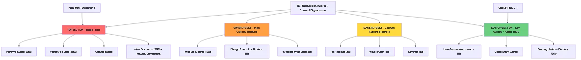
Vertical Organization Strategy:
TOP SECTION (Coolest area):
├── Busbars (positive, negative, ground)
├── Main disconnect breaker (highest current = most heat)
MIDDLE SECTION: ├── High-current branch breakers (inverter, charger) ├── Medium-current breakers (loads 30-60A)
BOTTOM SECTION (Hottest area due to convection): ├── Low-current breakers (lighting, controls, 10-20A) ├── Cable entry glands └── Drainage holes (if outdoor enclosure)
Horizontal Organization Strategy:
LEFT SIDE:                    RIGHT SIDE:
├── Source connections        ├── Load connections
├── Battery input            ├── Inverter output
├── Solar array input        ├── Branch circuits
└── Charge controller input  └── Accessory circuits
Benefits:
– Clear visual separation of source vs. load
– Easier troubleshooting (“left side dead = source problem”)
– Reduces wire crossing and clutter
Heat Management Layout:
Critical principle: Heat rises. Place highest-current (hottest) components at TOP of enclosure, allowing natural convection to carry heat upward and out through vents.
Incorrect Layout:
❌ WRONG:
TOP: Low-current breakers (20A)
MIDDLE: Medium breakers (60A)
BOTTOM: Main breaker (200A) ← Traps heat below, overheats entire enclosure
Correct Layout:
✓ CORRECT:
TOP: Main breaker (200A) ← Heat escapes upward naturally
MIDDLE: Medium breakers (60A)
BOTTOM: Low-current breakers (20A) ← Cooler air enters from below
High-current DC systems generate significant heat inside enclosures. Proper thermal design prevents:
– Breaker nuisance tripping (thermal derating)
– Insulation degradation (reduced wire lifespan)
– Component failure (electronics, capacitors)
– Fire hazards (overheated connections)
Heat Sources in a DC Breaker Box:
1. Breaker Internal Losses:
“`
Power dissipation = I² × R_breaker
Example: 100A breaker at full load
Internal resistance: ~0.0005Ω typical
Heat = (100A)² × 0.0005Ω = 5W per breaker
“`
2. Busbar Losses:
“`
Busbar resistance: ~0.0001Ω per foot for 1/4″ × 2″ copper
Example: 200A through 12″ busbar
Resistance: 0.0001Ω × 1ft = 0.0001Ω
Heat = (200A)² × 0.0001Ω = 4W
“`
3. Connection Losses:
“`
Good connection: ~50 microohms (0.00005Ω)
Poor connection: ~500 microohms (0.0005Ω)
At 200A:
Good: (200A)² × 0.00005Ω = 2W (acceptable)
Poor: (200A)² × 0.0005Ω = 20W (overheating!)
“`
Total Heat Load Example:
Solar system, 48V, 200A main breaker box:
- Main breaker (200A): 20W
- Inverter breaker (100A): 5W
- Charge controller breaker (60A): 2W
- 4× Branch breakers (20A each): 0.4W × 4 = 1.6W
- Busbar losses: 4W
- Connection losses (8 connections): 2W × 8 = 16W
Total: 48.6W heat generation at full load
Natural Convection (Passive Cooling):
For heat loads <50W in moderate climates:
Design Requirements:
– Top vent: 25-50 square inches minimum
– Bottom vent: 25-50 square inches minimum
– Vertical separation: >12 inches between vents
– Vent louvers: Weatherproof, insect-screened
Placement:
TOP VENT:
- Mount at highest point of enclosure
- Angle louvers down-and-out (prevents rain entry)
- Use labyrinth design (indirect path prevents water/dust)
BOTTOM VENT: – Mount at lowest point, but ABOVE potential flood level – Face downward (prevents splash entry) – Use coarse screen (prevents rodent entry)
Temperature Rise Calculation:
ΔT = Heat (Watts) ÷ (Airflow (CFM) × 1.76)Example: 50W heat, natural convection ~5 CFM (estimated) ΔT = 50 ÷ (5 × 1.76) = 5.7°C rise
Ambient 40°C + 5.7°C rise = 45.7°C interior (acceptable)
Forced Air Cooling (Active Cooling):
For heat loads >50W or hot climates:
Fan Sizing:
Required CFM = Heat (Watts) ÷ (ΔT target (°C) × 1.76)Example: 100W heat, target 10°C rise CFM = 100 ÷ (10 × 1.76) = 5.7 CFM minimum Select: 10-15 CFM fan for safety margin
Fan Types:
- 12V DC axial fan: 10-20 CFM typical, 1-3W power consumption
- Solar-powered fan: Off-grid installations
- Thermostat-controlled: Activates at 50°C, turns off at 40°C
Installation:
FAN LOCATION:
- Mount at TOP of enclosure (exhaust hot air)
- Or mount at SIDE-TOP (cross-flow ventilation)
- Never mount at bottom (blows cool air in, but inefficient)
WIRING: – Connect to lowest-priority 12V circuit – Use 1A fuse for protection – Consider bypass diode if fan fails (prevents backfeed)
Sealed Enclosure Considerations (NEMA 4/4X):
Sealed enclosures cannot use passive ventilation. Options:
1. Oversized Enclosure:
– 2-3× larger volume than required
– Provides thermal mass to absorb heat
– Temperature rise slower
2. External Heat Sink:
– Mount aluminum fins outside enclosure
– Conduct heat through enclosure wall
– Natural convection cools fins
3. Thermoelectric Cooling:
– Peltier cooling module (50-100W capacity)
– 12V DC powered
– Expensive ($150-300) but effective
4. Air Conditioning:
– Small enclosure AC units (100-300W capacity)
– Required for sensitive electronics
– Common in telecommunications
Wall Mounting (Most Common):
Exigences :
– Structural support: Minimum 100 lbs capacity (large enclosures + wire weight)
– Mounting height: 4-6 feet to center of enclosure (NEC 110.26)
– Horizontal mounting: Enclosure doors must open ≥90° without obstruction
– Vertical mounting: Top of enclosure minimum 6.5 feet above floor
Mounting Hardware:
WOOD STUDS:
- Use 1/4" × 3" lag bolts
- Minimum 4 bolts for enclosures >16" wide
- Pre-drill pilot holes (3/16" for 1/4" bolt)
- Use washers to distribute load
CONCRETE/MASONRY: – Use 1/4″ × 3″ concrete anchors (wedge or sleeve type) – Drill holes with hammer drill – Minimum 4 anchors – Verify enclosure level before final tightening
METAL STUDS: – Use toggle bolts or structural backing plate – Metal studs alone insufficient for large enclosures – Consider plywood backer board spanning multiple studs
Pedestal Mounting (Outdoor/Industrial):
Avantages :
– Elevates enclosure above flood level
– Prevents splash from ground-level water
– Easier cable entry from below
– Better ventilation (air circulation around all sides)
Construction:
CONCRETE PEDESTAL:
1. Pour concrete pad: 24" × 24" × 6" minimum
2. Embed J-bolts in wet concrete (4 bolts, 1/2" diameter)
3. Allow 7 days curing
4. Bolt enclosure base to J-bolts
5. Height: 18-36" typical
STEEL PIPE PEDESTAL: 1. Use 4″ schedule 40 steel pipe 2. Bury 3 feet deep in concrete footing 3. Mount enclosure to pipe with U-bolts 4. Apply rust-preventive paint
Knockout Holes (NEMA 1, Indoor):
Standard enclosures include pre-punched knockout locations:
– 1/2″ through 2″ conduit sizes
– Use knockout punch tool or hammer/screwdriver
– Install threaded conduit connector
– Apply locknut inside enclosure
Cable Glands (NEMA 3R/4/4X, Outdoor/Marine):
Weatherproof cable entry requires proper glands:
Compression Cable Gland:
Components:
- Body (threads into enclosure wall)
- Compression ring (squeezes around cable)
- O-ring seal (prevents water entry)
- Locknut (secures from inside)
Installation: 1. Drill hole matching gland diameter 2. Deburr hole edges 3. Thread gland body into hole from outside 4. Install O-ring on gland threads 5. Tighten locknut from inside (150-200 in-lbs torque) 6. Insert cable through gland 7. Tighten compression ring until snug (not crushing cable) 8. Apply silicone sealant around cable for extra protection
Cable Gland Sizing:
| Cable Size (AWG) | Cable OD (inches) | Required Gland Size |
|---|---|---|
| 10 AWG | 0.25″ | PG13.5 (13mm) |
| 6 AWG | 0.35″ | PG16 (16mm) |
| 2 AWG | 0.50″ | PG21 (21mm) |
| 1/0 AWG | 0.65″ | PG29 (29mm) |
| 4/0 AWG | 0.90″ | PG36 (36mm) |
Liquid-Tight Flexible Conduit (Marine/Vibration):
For marine or RV installations with vibration:
– Use liquid-tight flexible metallic conduit (LFMC)
– Continuous from enclosure to equipment
– Prevents vibration from loosening connections
– Watertight connectors at both ends
Equipment Grounding Requirements (NEC 250.110):
All metal enclosures must be grounded to prevent shock hazard:
Grounding Methods:
1. Internal Ground Busbar:
“`
– Mount copper ground busbar inside enclosure
– Use 6 AWG minimum conductor
– Connect busbar to enclosure with bonding screw
– Bond enclosure to main system ground
– All equipment grounds terminate to this busbar
“`
2. Enclosure Bonding:
“`
– Green bonding screw threads into enclosure
– Connects ground busbar to enclosure metal
– Ensures enclosure at ground potential
– Required for all metal enclosures (NEC 250.8)
“`
3. Grounding Electrode Conductor:
“`
– Connects enclosure ground to grounding electrode
– Size per NEC Table 250.66
– Typical: 6 AWG for systems <100A – Typical: 4 AWG for systems 100-200A – Run continuously (no splices) “`
Grounding Verification:
Testing Procedure:
1. Use multimeter in resistance mode
2. Measure enclosure to ground: Should be <1Ω
3. Measure enclosure to neutral (if grounded system): Should be <1Ω
4. If >1Ω: Check bonding screw tightness, clean contact surfaces
Cold-Rolled Steel (Powder-Coated):
Avantages :
– Low cost ($50-150 for NEMA 1)
– High strength and rigidity
– Good electromagnetic shielding (EMI/RFI)
– Easy to manufacture (standard tooling)
Inconvénients :
– Rusts if coating damaged
– Heavier weight (40-60 lbs for 20×24″ enclosure)
– Not suitable for marine environments
Meilleur pour : Indoor climate-controlled installations, residential solar equipment rooms
Galvanized Steel:
Avantages :
– Better corrosion resistance than powder coating
– Zinc coating sacrificial protection (self-healing)
– Moderate cost ($100-250 for NEMA 3R)
– Good mechanical strength
Inconvénients :
– Limited lifespan in marine environments (5-10 years)
– Zinc coating can degrade over time
– Must use stainless hardware (galvanic corrosion if mixed metals)
Meilleur pour : Outdoor solar installations in dry/moderate climates, RV exterior panels
Aluminum:
Avantages :
– Lightweight (50% of steel weight)
– Naturally corrosion-resistant (oxide layer)
– Non-magnetic (no eddy current losses)
– Easier to machine and modify
Inconvénients :
– Lower strength than steel (requires thicker walls)
– Higher cost ($200-400 for NEMA 4)
– Galvanic corrosion risk with copper/brass fittings
– Softer (easier to dent)
Meilleur pour : Marine freshwater environments, portable applications, weight-critical installations
304 Stainless Steel:
Avantages :
– Excellent corrosion resistance (general environments)
– High strength and durability
– Professional appearance (bright finish)
– 20-30 year lifespan outdoors
Inconvénients :
– High cost ($400-700 for NEMA 4X)
– Pitting corrosion in saltwater (chloride attack)
– Requires stainless hardware throughout
Meilleur pour : Coastal environments (not direct salt spray), industrial facilities, high-end installations
316 Stainless Steel:
Avantages :
– Superior corrosion resistance (molybdenum content)
– Saltwater resistant (2-3% molybdenum prevents pitting)
– 30-40 year lifespan in marine environments
– Best material for harsh environments
Inconvénients :
– Very high cost ($600-1000+ for NEMA 4X)
– Heavier than aluminum
– Requires 316 stainless hardware throughout
Meilleur pour : Direct saltwater exposure (boats, offshore platforms), chemical plants, tropical marine
Polycarbonate/Fiberglass (Non-Metallic):
Avantages :
– Immune to corrosion
– Lightweight
– Transparent covers available (view components without opening)
– UV-resistant formulations
– Electrically non-conductive (no grounding required)
Inconvénients :
– Lower strength (requires internal reinforcement)
– UV degradation over time (yellowing)
– No EMI shielding
– Higher cost ($300-500 for NEMA 4X)
– Difficult to modify in field
Meilleur pour : Corrosive chemical environments, weight-critical applications, hazardous locations
Matching Materials Critical:
Galvanic corrosion occurs when dissimilar metals contact in presence of electrolyte (water):
Galvanic Series (Most Noble → Most Active):
Platinum (most noble - least corrosive)
Gold
316 Stainless Steel
304 Stainless Steel
Brass
Copper
Aluminum
Galvanized Steel
Carbon Steel (most active - most corrosive)
Zinc
Rule: Use fasteners made of same material as enclosure OR more noble material.
Correct Combinations:
– 316 SS enclosure + 316 SS hardware ✓
– Aluminum enclosure + 316 SS hardware ✓
– Steel enclosure + steel hardware ✓
Incorrect Combinations (Will Corrode):
– 316 SS enclosure + steel hardware ✗ (steel corrodes)
– Aluminum enclosure + steel hardware ✗ (aluminum corrodes)
– Aluminum enclosure + copper busbars ✗ (aluminum corrodes without isolation)
Isolation Methods:
– Use nylon washers between dissimilar metals
– Apply dielectric grease (blocks electrolyte)
– Use stainless steel throughout (most compatible)
Quarterly (Marine/RV) or Semi-Annually (Fixed):
– Visual inspection for rust, corrosion, damage
– Check door seal gasket condition (replace if cracked)
– Verify all breakers labeled correctly
– Check for water infiltration (look for staining)
– Clean ventilation screens (remove dust, insects)
Annuellement :
– Torque check all connections (thermal cycling loosens)
– Verify ground continuity <1Ω – Thermal imaging scan under load – Inspect internal wiring for chafing or damage – Test door latch/lock mechanism – Re-apply anti-corrosion treatments (marine environments)
Problem 1: Water Entry in NEMA 3R/4 Enclosure
Symptômes :
– Rust on internal components
– Tripped breakers after rain
– Water pooling at bottom
Les causes :
– Damaged door gasket
– Cable gland not tightened
– Mounting angle allows water pooling
– Drainage holes blocked
Solutions :
1. Replace door gasket (closed-cell foam, 1/4" thick)
2. Re-tighten all cable glands (torque to spec)
3. Verify enclosure mounted plumb (use level)
4. Drill 1/4" drainage holes at bottom corners (outdoor enclosures only)
5. Apply silicone sealant around cable entries as backup
Problem 2: Overheating Interior
Symptômes :
– Breakers trip at <80% rated current – Interior temperature >70°C
– Discolored wires or components
– Burnt smell
Les causes :
– Insufficient ventilation
– Oversized breakers generating excess heat
– Poor connections (high resistance)
– Direct sunlight exposure
Solutions :
1. Add ventilation (top + bottom vents if permitted by rating)
2. Install 12V DC exhaust fan (10-15 CFM)
3. Relocate to shaded area or add sunshade
4. Check all connections with thermal camera (retorque hot spots)
5. Consider upgrading to larger enclosure (more thermal mass)
Problem 3: Corrosion Despite Proper Rating
Symptômes :
– Rust on hinges, latches, or mounting hardware
– Busbar corrosion (white or green powder)
– Loose connections due to corrosion
Les causes :
– Dissimilar metals (galvanic corrosion)
– Humidity trapped inside sealed enclosure
– Salt spray beyond rating specification
– Damaged coating allowing moisture
Solutions :
1. Replace all hardware with 316 stainless steel
2. Install desiccant packs inside (replace quarterly)
3. Apply protective coatings:
   - Boeshield T-9 on hinges/latches
   - DeoxIT on electrical connections
   - Corrosion-X on busbars
4. Upgrade to higher-rated enclosure (IP67 vs IP65)
5. Improve drainage (sealed enclosures trap condensation)
Rittal AE Compact Enclosure – Stainless Steel
- Prix: $600-1200
- Caractéristiques: 304/316 SS, IP66, modular internal mounting
- Sizes: 12×16″ to 36×48″
- Meilleur pour: Industrial, marine, chemical plants
- Garantie: 5 years
Hoffman A-Series – NEMA 4X Stainless
- Prix: $500-1000
- Caractéristiques: 304 SS standard, 316 SS available, clamp-cover design
- Sizes: Wide range, 12×12″ to 48×60″
- Meilleur pour: Offshore, saltwater marine, food processing
- Garantie: 3 years
Eaton Crouse-Hinds EB Series – NEMA 3R
- Prix: $150-400
- Caractéristiques: Powder-coated steel, rainproof, knockouts
- Sizes: 12×16″ to 24×36″
- Meilleur pour: Outdoor solar, rooftop installations
- Garantie: 1 year
Hammond 1418 Series – NEMA 4
- Prix: $200-500
- Caractéristiques: Powder-coated steel, continuous hinge, foam gasket
- Sizes: 10×12″ to 30×36″
- Meilleur pour: Industrial, outdoor equipment
- Garantie: 2 years
BUD Industries NEMA Boxes
- Prix: $50-150
- Caractéristiques: Basic NEMA 1/3R, steel or aluminum
- Sizes: 8×10″ to 20×24″
- Meilleur pour: Indoor residential, garage installations
- Garantie: 90 days
Fibox ARCA Series – Polycarbonate
- Prix: $80-250
- Caractéristiques: Non-metallic, UV-resistant, IP67
- Sizes: 8×12″ to 20×28″
- Meilleur pour: Corrosive environments, lightweight applications
- Garantie: 1 year
1. What’s the difference between a circuit breaker box and a combiner box?
A circuit breaker box distributes power to multiple load circuits with individual overcurrent protection (breakers) for each circuit. A combiner box consolidates multiple solar array strings into a single output, typically using only fuses (not breakers) without distribution to loads. Breaker boxes are for load distribution; combiner boxes are for source consolidation. Solar systems often use both: combiner at the array, breaker box for home distribution.
2. Can I install a DC circuit breaker box outdoors without weather protection?
Only if rated NEMA 3R (rainproof) or higher, or IP54+ (international). Indoor-rated enclosures (NEMA 1) will fail within months outdoors due to moisture ingress, UV degradation, and corrosion. Even NEMA 3R enclosures benefit from additional protection like roof overhangs or sunshades. Marine environments require NEMA 4X (IP66/67) with stainless steel construction due to salt spray corrosion.
3. How do I calculate the right size enclosure for my breakers?
Measure all components (breakers, busbars, surge protectors), add NEC wire bending space requirements (Table 312.6 – typically 4-6 inches for large conductors), add 2-3 inches clearance between components, and select the next standard size up. Example: 18″ of breakers + 6″ bending space + 2″ clearance = 26″ minimum; select 30″ wide enclosure. Always oversize by 20-30% for future expansion and heat dissipation.
4. Do I need ventilation in my DC breaker box?
Depends on heat load and environmental rating. NEMA 1 (indoor) enclosures should have ventilation if total current exceeds 100A continuously. NEMA 3R (outdoor) can be vented if designed properly (labyrinth vents prevent rain). NEMA 4/4X (sealed waterproof) cannot be vented—use oversized enclosure, external heat sinks, or active cooling instead. Calculate heat load: >50W requires enhanced cooling.
5. Can I mount DC breakers in the same enclosure as AC breakers?
Not recommended and often prohibited by code. AC and DC systems require separate enclosures for safety: accidental cross-connection can damage equipment or create shock hazards. NEC 690.4(D) requires clear separation and labeling. If absolutely necessary, use physical barriers (internal dividers) and label clearly: “WARNING: AC AND DC CIRCUITS – DO NOT INTERMIX.” Always check local electrical code before combining.
6. What’s better: steel or aluminum enclosure for marine use?
For freshwater marine: Aluminum offers best value (lightweight, naturally corrosion-resistant). For saltwater marine: 316 stainless steel is superior despite higher cost—aluminum can pit in saltwater and requires more maintenance. Avoid plain steel in any marine environment (rusts rapidly). Use 316 SS hardware throughout regardless of enclosure material to prevent galvanic corrosion between dissimilar metals.
7. How do I prevent condensation inside a sealed DC breaker box?
Condensation forms when warm humid air cools (night, temperature drops). Prevention methods: (1) Install desiccant packs inside, replace quarterly; (2) Use thermostat-controlled heater strip (5-10W) to keep interior above dew point; (3) Apply conformal coating to busbars/connections; (4) Use breather vents with desiccant (allows pressure equalization without moisture); (5) Locate enclosure in temperature-stable area (avoid direct sunlight). Check for condensation monthly in humid climates.
The DC circuit breaker box enclosure is the foundation of safe, durable electrical distribution. Proper selection based on environmental conditions, adequate sizing for components and thermal management, and professional installation techniques ensure decades of reliable service.
Liste de contrôle pour la sélection :
– [ ] Environmental rating matches location (NEMA/IP)
– [ ] Material suitable for corrosion exposure
– [ ] Size accommodates components + NEC clearances + 30% expansion
– [ ] Thermal management adequate for heat load
– [ ] Mounting location provides code-required working clearances
– [ ] Hardware materials compatible (prevent galvanic corrosion)
Installation Checklist:
– [ ] Structural mounting adequate for weight (100+ lbs typical)
– [ ] Enclosure level and plumb
– [ ] Ground bonding <1Ω resistance verified – [ ] All cable entries sealed weatherproof – [ ] Component layout optimized for heat dissipation – [ ] All circuits labeled clearly – [ ] Documentation inside door (one-line diagram) Maintenance Checklist:
– [ ] Quarterly: Visual inspection, clean vents, check seals
– [ ] Annually: Torque check, thermal imaging, ground test
– [ ] Marine: Re-apply corrosion protection annually
– [ ] Replace gaskets every 3-5 years
– [ ] Plan enclosure replacement: 15-20 years (steel), 25-30 years (stainless)
Investment Perspective:
An enclosure protecting $10,000-50,000 of electrical infrastructure warrants quality selection. The cost difference between budget ($100) and premium ($500) enclosures is negligible compared to replacement costs or downtime from premature failure.
For critical applications—marine life-safety systems, off-grid homes, commercial solar—invest in 316 stainless steel NEMA 4X enclosures. For standard residential solar in moderate climates, NEMA 3R aluminum offers excellent value. For indoor climate-controlled environments, standard powder-coated steel suffices.
The breaker box is visible evidence of installation quality—a well-designed, properly installed enclosure demonstrates professional engineering and ensures long-term reliability.
A circuit breaker box distributes power to multiple load circuits with individual overcurrent protection (breakers) for each circuit. A combiner box consolidates multiple solar array strings into a single output using fuses without distribution to loads. Solar systems often use both: combiner at the array, breaker box for home distribution.
Only if rated NEMA 3R (rainproof) or higher, or IP54+ (international). Indoor-rated enclosures (NEMA 1) will fail within months outdoors due to moisture ingress, UV degradation, and corrosion. Marine environments require NEMA 4X (IP66/67) with stainless steel construction.
Measure all components (breakers, busbars, surge protectors), add NEC wire bending space requirements (Table 312.6 – typically 4-6 inches), add 2-3 inches clearance, and select the next standard size up. Always oversize by 20-30% for future expansion and heat dissipation.
Depends on heat load and rating. NEMA 1 enclosures should have ventilation if current exceeds 100A continuously. NEMA 3R can be vented with labyrinth vents. NEMA 4/4X sealed enclosures cannot be vented—use oversized enclosure or active cooling if heat load exceeds 50W.
Not recommended and often prohibited by code. AC and DC systems require separate enclosures for safety. NEC 690.4(D) requires clear separation and labeling. If necessary, use physical barriers and clear warning labels. Always check local electrical code.
For freshwater: Aluminum offers best value (lightweight, naturally corrosion-resistant). For saltwater: 316 stainless steel is superior despite higher cost. Avoid plain steel in marine environments. Use 316 SS hardware throughout to prevent galvanic corrosion.
Prevention methods: Install desiccant packs (replace quarterly), use thermostat-controlled heater strip (5-10W), apply conformal coating to connections, use breather vents with desiccant, locate in temperature-stable area. Check monthly in humid climates.