Indirizzo
304 Nord Cardinale
St. Dorchester Center, MA 02124
Orario di lavoro
Da lunedì a venerdì: dalle 7.00 alle 19.00
Fine settimana: 10.00 - 17.00
Indirizzo
304 Nord Cardinale
St. Dorchester Center, MA 02124
Orario di lavoro
Da lunedì a venerdì: dalle 7.00 alle 19.00
Fine settimana: 10.00 - 17.00


La comprensione della progettazione di un sistema completo di protezione dalle sovratensioni in corrente continua consente di adottare strategie efficaci di difesa in profondità per gli impianti fotovoltaici. Questa guida tecnologica avanzata esamina i principi di coordinamento degli SPD multistadio, i concetti di zona di protezione dai fulmini (LPZ), l'analisi della distribuzione dell'energia e l'architettura della protezione a livello di sistema. I tecnici della protezione e i progettisti di sistemi troveranno metodologie di coordinamento dettagliate, definizioni dei confini delle zone e strategie di ottimizzazione delle prestazioni per sistemi completi di protezione dalle sovratensioni fotovoltaiche.
La protezione contro le sovratensioni in un unico punto, mediante installazioni isolate di SPD, rappresenta un approccio inadeguato per i moderni impianti fotovoltaici esposti a molteplici vettori di minaccia. I fulmini iniettano energia attraverso il collegamento diretto dei conduttori, l'induzione elettromagnetica e i meccanismi di innalzamento del potenziale di terra che richiedono una protezione coordinata in più punti del sistema. Una protezione efficace contro le sovratensioni in corrente continua impiega un'architettura sistematica di difesa in profondità che distribuisce la mitigazione delle minacce attraverso stadi di protezione in cascata.
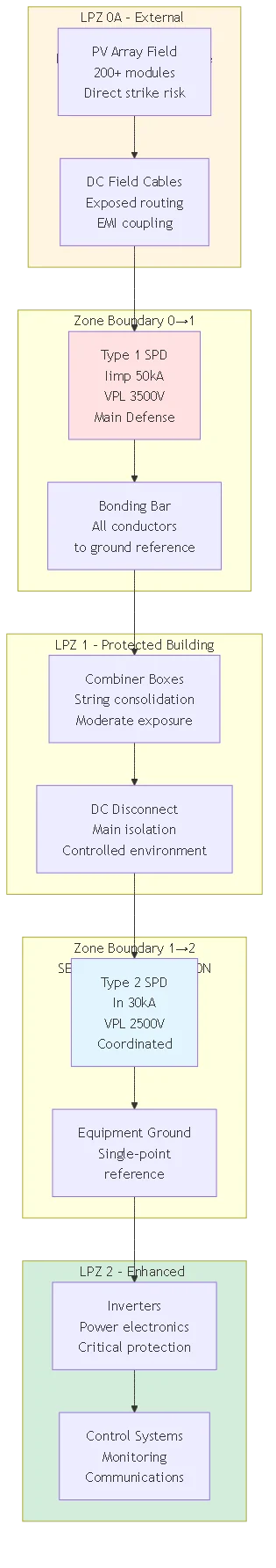
La norma IEC 62305-4 stabilisce la metodologia delle zone di protezione dai fulmini, dividendo le installazioni in regioni in base alla gravità della minaccia elettromagnetica. Ogni attraversamento dei confini della zona richiede misure di protezione adeguate che riducano le tensioni e le correnti di sovratensione a livelli accettabili per le apparecchiature della zona di destinazione. Questo approccio sistematico sostituisce la collocazione ad hoc degli SPD con un'architettura di protezione ingegnerizzata, che abbina i livelli di minaccia alle capacità di protezione.
LPZ 0 (esterno non protetto): Zona più esterna direttamente esposta ai fulmini e all'intensità del campo elettromagnetico. Gli impianti fotovoltaici montati sui tetti degli edifici o i rack montati a terra occupano la LPZ 0A con rischio di attacco diretto dei fulmini. Intensità del campo elettromagnetico nella LPZ 0: H ≈ 200 A/m durante le fulminazioni vicine. Le apparecchiature installate nella LPZ 0 richiedono una struttura robusta, in grado di resistere all'esposizione ambientale e alle interferenze elettromagnetiche.
LPZ 1 (Interno di edificio protetto): Prima zona protetta in cui i fulmini diretti sono impediti dal sistema di protezione esterno (terminali aerei, calate, rete di collegamento), ma le sovratensioni indotte penetrano attraverso i conduttori in ingresso. Il campo elettromagnetico si attenua a H ≈ 20 A/m grazie alla schermatura magnetica della struttura dell'edificio. Le scatole di combinatori e le cassette di sezionamento CC sono tipicamente installate in LPZ 1 e richiedono una protezione contro le sovracorrenti condotte sui circuiti CC che entrano da LPZ 0.
LPZ 2+ (protezione avanzata): Zone interne con isolamento elettromagnetico progressivamente migliore, ottenuto grazie a schermature, filtri e SPD in cascata. Gli interni degli inverter e l'elettronica di controllo sensibile occupano la LPZ 2, con un'esposizione minima al campo elettromagnetico (H ≈ 2 A/m) e minacce di sovratensioni condotte ridotte. Le apparecchiature nella LPZ 2 presuppongono un'adeguata protezione a monte che limita i transitori in ingresso ad ampiezze gestibili.
| Zona di protezione | Livello di minaccia | Apparecchiature fotovoltaiche tipiche | Tipo di SPD richiesto | Livello di protezione della tensione |
|---|---|---|---|---|
| LPZ 0A (esterno) | Colpi massimi diretti | Moduli fotovoltaici, strutture di montaggio | Tipo 1 al confine di zona | 2500-4000V |
| LPZ 1 (edificio) | Sovratensioni moderate indotte | Combinatori, sezionatori CC | Tipo 2 coordinato | 1800-2500V |
| LPZ 2 (inverter) | Transitori a bassa frequenza | Inverter, sistemi di controllo | Protezione fine di tipo 2/3 | 1500-2000V |
Ogni attraversamento della zona di protezione dai fulmini richiede misure di protezione dalle sovratensioni adeguate che riducano la minaccia elettromagnetica a livelli compatibili con le apparecchiature della zona di destinazione. La transizione da LPZ 0 a LPZ 1 rappresenta il punto di protezione più critico che sperimenta la massima energia di sovratensione e che richiede una robusta capacità SPD di tipo 1. Calcolare il valore minimo dell'SPD a questo confine in base all'analisi del livello di protezione dai fulmini (LPL) secondo la norma IEC 62305-2.
L'installazione dell'SPD del confine di zona segue regole sistematiche:
- Installare gli SPD il più vicino possibile all'attraversamento dei confini, riducendo al minimo la lunghezza dei conduttori non protetti.
- Collegare tutti i conduttori (alimentazione, dati, controllo) che entrano nella zona al riferimento comune di messa a terra sul confine.
- Mantenere la continuità elettromagnetica delle schermature di zona attraverso una corretta posa dei conduttori e la terminazione delle schermature.
- Verificare un'adeguata separazione o disaccoppiamento dei conduttori tra gli SPD ai confini delle zone adiacenti.
Quando più servizi entrano nell'edificio in punti diversi, stabilire confini di zona separati in ogni punto di ingresso, anziché instradare i conduttori non protetti attraverso l'interno dell'edificio fino alla postazione di protezione centrale. Questa protezione distribuita evita che le sovratensioni si propaghino attraverso il cablaggio dell'edificio, creando accoppiamenti secondari e innalzando il potenziale di terra che si ripercuotono sulle apparecchiature sensibili distanti dal punto di ingresso.
💡 Approfondimento chiave: Il concetto di zona di protezione dai fulmini fornisce un quadro ingegneristico che sostituisce il posizionamento intuitivo degli SPD con un'architettura di protezione sistematica. La definizione di confini chiari della zona e la specificazione dei tipi di SPD appropriati a ogni incrocio eliminano le congetture dalla progettazione della protezione contro le sovratensioni, garantendo una copertura completa delle minacce senza inutili sovraspecifiche.
La protezione contro le sovratensioni a più stadi distribuisce l'energia totale delle sovratensioni su più SPD, anziché concentrare l'intera minaccia su un singolo dispositivo. Gli SPD a monte intercettano i componenti ad alta energia colpiti direttamente, mentre gli SPD a valle gestiscono i transitori residui dopo l'attenuazione dell'impedenza del conduttore. Questa distribuzione dell'energia prolunga la durata degli SPD e fornisce una difesa in profondità, proteggendo dai guasti dei dispositivi a monte o dalle sovratensioni che superano la capacità dei singoli SPD.
Calcolare la distribuzione dell'energia utilizzando l'impedenza del conduttore e le caratteristiche della forma d'onda della corrente di sovratensione. Per la corrente di fulmine con picco Im e tempo di salita tr, la tensione sviluppata attraverso l'induttanza del conduttore L: V = L × (Im/tr). Questa caduta di tensione induttiva si sottrae alla tensione di bloccaggio dell'SPD a monte prima di raggiungere l'SPD a valle. Esempio: L'SPD di tipo 1 a monte si blocca a 3500 V, un cavo di 20 metri fornisce un'induttanza di 30μH, una sovracorrente di 10kA con una salita di 1μs genera una caduta di V = 30μH × (10kA/1μs) = 300V. L'SPD a valle vede 3500V - 300V = 3200V di stress ridotto.
Il rapporto di ripartizione dell'energia dipende dai livelli di protezione della tensione dell'SPD e dall'impedenza del conduttore intermedio. In un sistema perfettamente coordinato, l'SPD a monte devia 70-90% di energia di sovratensione, mentre quello a valle gestisce i restanti 10-30%. Un cattivo coordinamento - separazione insufficiente dei conduttori o rapporti VPL non corretti - fa sì che entrambi gli SPD conducano simultaneamente, riducendo l'efficacia della divisione dell'energia e creando potenzialmente riflessioni di tensione che danneggiano le apparecchiature protette.
La norma IEC 61643-12 raccomanda una separazione minima dei conduttori tra gli stadi SPD coordinati, in modo da garantire un disaccoppiamento adeguato per il funzionamento indipendente. La separazione richiesta dipende dalla differenza di tensione tra i livelli di protezione degli SPD e dal tasso di aumento della corrente di sovratensione previsto. Utilizzare la formula: Lmin = (VPL_upstream - VPL_downstream) × tr / Im dove i valori VPL sono i livelli di protezione, tr è il tempo di salita della corrente e Im è la massima corrente di sovratensione prevista.
Esempio di calcolo per un sistema a due stadi da 1000 V:
- Tipo 1 a monte: VPL = 3500V
- Tipo 2 a valle: VPL = 2800V
- Sovratensione prevista: Im = 20kA, tr = 8μs (forma d'onda 8/20μs)
- Induttanza richiesta: Lmin = (3500V - 2800V) × 8μs / 20kA = 700V × 8μs / 20kA = 280nH
- A 1,5μH/metro induttanza tipica del cavo: separazione minima = 280nH / 1,5μH/m ≈ 187 metri
Aspettate, questo calcolo sembra sbagliato. Lasciatemi ricalcolare:
In realtà, la formula corretta dovrebbe essere: Lmin = (VPL_up - VPL_down) / (dI/dt), dove dI/dt = Im/tr
Lmin = (3500V - 2800V) / (20kA/8μs) = 700V / 2,5kA/μs = 280μH
A 1,5μH/metro: separazione = 280μH / 1,5μH/m ≈ 187 metri - una lunghezza improponibile!
Consentitemi di utilizzare un approccio più pratico: Per una forma d'onda di 8/20μs, la salita tipica di/dt ≈ 10kA/μs per Im = 20kA.
Lmin = (VPL_up - VPL_down) / (di/dt) = 700V / 10kA/μs = 70μH minimo
A 1,5μH/m: separazione = 70μH / 1,5μH/m ≈ 47 metri minimo pratico.
Tuttavia, la raccomandazione semplificata IEC 61643-12: un minimo di 10 metri fornisce circa 15μH adeguati alla maggior parte delle applicazioni residenziali/commerciali. I sistemi di grandi dimensioni su scala pubblica prevedono naturalmente una separazione di 50-200 metri che fornisce 75-300μH, garantendo un eccellente coordinamento con un margine sostanziale.
Quando la separazione fisica non è sufficiente, installare induttori di disaccoppiamento discreti tra gli stadi SPD. Le reattanze di linea da 15-50μH con capacità di corrente corrispondente ai requisiti del circuito forniscono un coordinamento equivalente in installazioni compatte. Queste induttanze devono gestire la corrente continua del sistema e le correnti di sovratensione di breve durata senza che la saturazione comprometta l'efficacia del coordinamento.
| Separazione dei conduttori | Induttanza tipica | Qualità del coordinamento | Applicazione |
|---|---|---|---|
| <5 metri | <7,5μH | Scarso - Rischio di fallimento del coordinamento | Non consigliato: aggiungere un induttore |
| 10-15 metri | 15-22μH | Accettabile - Minimo secondo IEC | Residenziale, commerciale compatto |
| 20-50 metri | 30-75μH | Buono - Coordinamento affidabile | Sistemi commerciali standard |
| >100 metri | >150μH | Eccellente - Isolamento naturale | Array su scala industriale e distribuiti |
⚠️ Importante: Un coordinamento inadeguato degli SPD fa sì che i dispositivi a monte e a valle si attivino contemporaneamente, creando oscillazioni di corrente e riflessioni di tensione. Questo funzionamento non coordinato può effettivamente peggiorare la protezione delle apparecchiature rispetto a un SPD monostadio correttamente selezionato, producendo tensioni transitorie più elevate ai terminali delle apparecchiature protette rispetto a quelle che uno dei due SPD sarebbe in grado di fornire da solo.
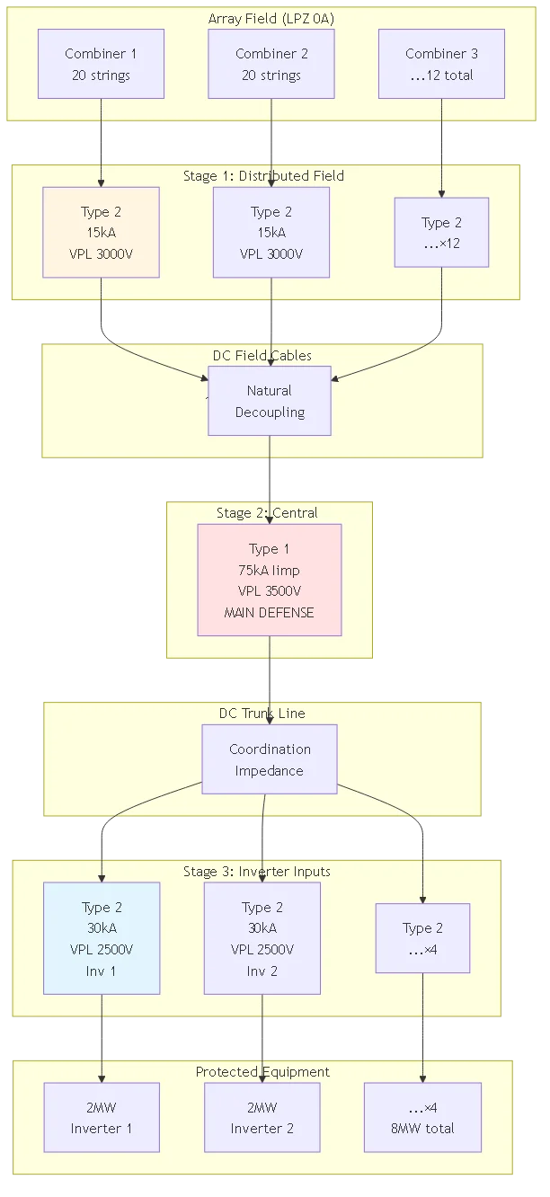
Le installazioni fotovoltaiche su scala industriale e critica beneficiano di una topologia SPD a tre stadi che massimizza l'affidabilità della protezione attraverso strati di difesa ridondanti. Questa architettura installa la protezione primaria all'origine dell'array (stadio 1), la protezione secondaria ai combinatori principali o ai ricombinatori (stadio 2) e la protezione terziaria agli ingressi dei singoli inverter (stadio 3). Ogni fase intercetta i componenti di sovratensione appropriati per la sua posizione, creando una difesa completa in profondità.
Fase 1 - Protezione del campo di array:
Installare SPD di tipo 2 (In = 15-20kA) in corrispondenza delle singole posizioni dei combinatori di stringa in tutto il campo dell'array. Questi SPD distribuiti intercettano le sovratensioni a livello di stringa derivanti da colpi diretti a sezioni specifiche dell'array, impedendo l'accoppiamento dell'energia su stringhe parallele attraverso l'infrastruttura DC comune. Spaziatura di fase 1: in genere 20-50 metri tra i combinatori che garantiscono un isolamento naturale tra gli SPD dei combinatori adiacenti.
Fase 2 - Protezione della raccolta centrale:
Installare robusti SPD di tipo 1 (Iimp = 50-100kA) nel punto di raccolta centrale (ricombinatore principale o combinatore del campo di array) dove tutte le uscite delle stringhe si consolidano prima di essere instradate alla stazione di inverter. Lo stadio 2 rappresenta la massima concentrazione di energia di sovratensione e richiede la massima capacità degli SPD di gestire le minacce combinate dell'intero campo di array. Separazione dallo stadio 1: 100-500 metri, tipico delle grandi installazioni.
Fase 3 - Protezione dell'ingresso dell'inverter:
Installare SPD di tipo 2 (In = 30-40kA) su ciascun ingresso CC dell'inverter per fornire lo stadio di protezione finale per l'elettronica di potenza sensibile. Gli SPD di tipo 3 gestiscono i transitori residui che bypassano la protezione a monte o le tensioni indotte sui cavi di ingresso CC dell'inverter. Separazione dallo stadio 2: minimo 15-50 metri, a seconda del layout dell'impianto.
Una protezione efficace contro le sovratensioni a più stadi richiede un'architettura di messa a terra integrata che colleghi tutti i punti di installazione degli SPD a un sistema di elettrodi di terra comune a bassa impedenza. Un cattivo coordinamento della messa a terra crea loop di massa che fanno circolare le correnti di sovratensione attraverso il telaio delle apparecchiature, causando potenzialmente danni nonostante la presenza degli SPD. Progettare il sistema di messa a terra come elemento di protezione essenziale che merita la stessa attenzione ingegneristica della scelta degli SPD.
Riferimento di terra a punto singolo:
Stabilire un punto di riferimento per la messa a terra (in genere l'ingresso principale del servizio o il bus di terra dell'apparecchiatura centrale) in cui terminano tutti i conduttori degli elettrodi di terra. Tutti gli SPD presenti nell'impianto si collegano a questo punto di riferimento tramite conduttori di terra radiali, evitando più percorsi di terra paralleli che creano correnti circolanti. Il riferimento a un unico punto garantisce che tutti gli SPD condividano un potenziale di terra comune durante gli eventi di sovratensione, consentendo un funzionamento coordinato.
Sistema di elettrodi di messa a terra:
La norma IEC 62305 raccomanda una resistenza degli elettrodi di messa a terra <10Ω per i sistemi di protezione contro i fulmini, mentre <1Ω è preferibile per le installazioni elettroniche sensibili. Raggiungere una bassa resistenza attraverso barre di terra multiple (minimo 3 metri di profondità e 6 metri di distanza), elettrodi rivestiti in calcestruzzo (armatura di fondazione), griglie di terra (rete di rame sotto le apparecchiature) o sistemi di elettrodi combinati. Testare annualmente la resistenza degli elettrodi per verificare che le prestazioni non si siano degradate a causa della corrosione o delle variazioni delle condizioni del terreno. Legami e piani equipotenziali:
Collegare tutta l'infrastruttura metallica (telai degli array, sistemi di condotti, telai delle apparecchiature, passerelle per cavi, acciaio strutturale) al sistema di elettrodi di messa a terra, creando un piano equipotenziale che impedisca differenze di tensione durante gli eventi di sovratensione. Utilizzare conduttori di collegamento in rame di almeno 6 AWG con connessioni a compressione o a saldatura esotermica, evitando connessioni bullonate soggette ad allentamento e corrosione. Il collegamento equipotenziale riduce gli effetti di innalzamento del potenziale di terra (GPR) che possono danneggiare le apparecchiature anche con SPD adeguatamente dimensionati.
La protezione avanzata contro le sovratensioni si avvale di progetti di elementi ibridi che combinano tecnologie complementari ottimizzando la velocità di risposta, la capacità energetica e le caratteristiche di bloccaggio della tensione. Gli ibridi varistore all'ossido di metallo (MOV) + tubo a scarica di gas (GDT) offrono una capacità di corrente elevata del GDT (100kA+) con una risposta rapida del MOV che impedisce la sovratensione durante il ritardo di ionizzazione del GDT. Questi ibridi sono adatti alle posizioni di protezione primaria (limiti LPZ 0→1) che richiedono la massima gestione dell'energia.
Risposta ibrida a tappe:
1. L'arrivo della sovracorrente innesca una rapida conduzione del MOV (risposta <50ns) che fornisce una limitazione iniziale della tensione. L'aumento della corrente di sovratensione provoca la ionizzazione del GDT una volta che la tensione raggiunge la soglia di breakdown (~500-1000V) 3. La formazione dell'arco del GDT devia la maggior parte della corrente di sovratensione (decine di kA) dal MOV 4. Il MOV continua a limitare la tensione residua durante la conduzione del GDT, mantenendo un serraggio stretto 5. Il MOV continua a limitare la tensione residua durante la conduzione del GDT, mantenendo il serraggio stretto 5. Dopo il passaggio della sovracorrente, il GDT si deionizza e il MOV ritorna allo stato di standby ad alta impedenza.
Gli ibridi diodo a valanga al silicio (SAD) + MOV ottimizzano la protezione delle apparecchiature sensibili che richiedono il più stretto serraggio di tensione possibile. Il SAD fornisce una risposta sub-nanosecondo e una limitazione precisa della tensione (1,5-1,8× MCOV), mentre il MOV gestisce l'assorbimento dell'energia di massa. Questi ibridi premium costano 40-60% in più rispetto ai dispositivi solo MOV, ma offrono una protezione superiore per l'elettronica di potenza degli inverter costosi, dove i margini di tolleranza della tensione sono minimi.
La protezione attiva contro le sovratensioni di nuova generazione impiega circuiti di commutazione a semiconduttore che consentono di bloccare la tensione in modo quasi teorico. I raddrizzatori controllati al silicio (SCR) o i transistor bipolari a griglia isolata (IGBT) si attivano in pochi microsecondi dopo aver rilevato l'aumento della tensione di sovratensione, cortocircuitando la corrente di sovratensione verso terra attraverso un percorso a bassa impedenza. Il bloccaggio attivo raggiunge VPL 20-30% inferiori rispetto ai dispositivi passivi equivalenti a varistore, migliorando significativamente il margine di protezione delle apparecchiature.
I vantaggi degli SPD attivi includono il controllo preciso della tensione indipendentemente dall'entità della corrente di sovratensione, l'assenza di degrado dovuto all'esposizione ripetuta alle sovratensioni (a differenza dei MOV che consumano materiale a ogni evento) e le funzionalità di monitoraggio remoto che segnalano lo stato del dispositivo e le caratteristiche dell'evento di sovratensione. Svantaggi: costo più elevato ($800-1500 contro $300-600 per i passivi), elettronica complessa che richiede alimentazione ausiliaria e potenziali modalità di guasto non presenti nei semplici dispositivi passivi.
Considerate la tecnologia SPD attiva per le applicazioni ultra-sensibili - centri dati, strutture mediche, produzione di precisione - dove i danni alle apparecchiature causati da un blocco della tensione inadeguato superano il costo del sistema di protezione. Le installazioni fotovoltaiche standard raramente giustificano la spesa per la protezione attiva, tranne che per i progetti critici su scala pubblica, dove brevi interruzioni dell'inverter costano decine di migliaia di euro di mancati introiti.
Verificare il coordinamento degli SPD multistadio attraverso l'analisi della distribuzione della corrente di sovratensione, calcolando la divisione della corrente prevista tra i percorsi di protezione in parallelo. Utilizzare l'analisi nodale o la simulazione SPICE modellando il sistema SPD distribuito come una rete di resistenze dipendenti dalla tensione (che rappresentano gli SPD) collegate attraverso impedenze induttive (induttanza del cavo). Questa analisi rivela se gli SPD a monte gestiscono effettivamente l'energia prevista o se gli SPD a valle si comportano prematuramente, indicando un guasto di coordinamento.
Analisi semplificata a due stadi utilizzando le caratteristiche di tensione-corrente:
- Tensione SPD a monte: V1 = f1(I1) dove f1 è la curva I-V dell'SPD a monte
- Tensione SPD a valle: V2 = f2(I2) dove f2 è la curva I-V dell'SPD a valle
- Caduta di tensione dell'impedenza di accoppiamento: VL = L × dI/dt
- Relazione di tensione: V1 = V2 + VL durante l'evento di sovratensione
Per una corretta coordinazione, l'SPD a monte conduce per primo quando V1 raggiunge la sua soglia, mentre V2 rimane al di sotto della soglia a valle. Calcolare l'induttanza di accoppiamento critica Lcrit per garantire la coordinazione: Lcrit ≥ (Vthreshold_downstream - Vthreshold_upstream) × tr / Isurge. Se l'induttanza di installazione effettiva è < Lcrit, l'SPD a valle può condurre prematuramente, causando un errore di coordinamento.
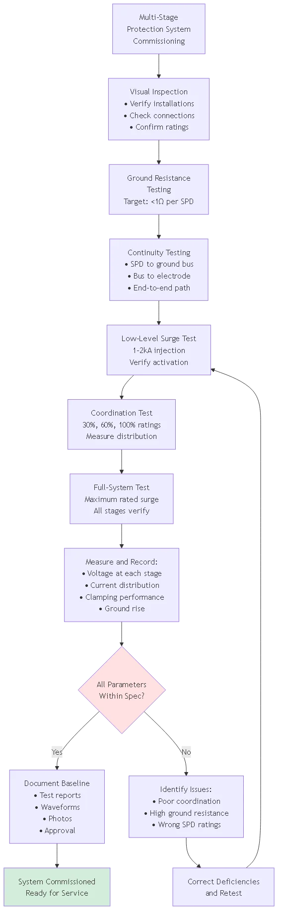
La messa in funzione dei sistemi di protezione multistadio si avvale di generatori di sovratensioni portatili che simulano le forme d'onda dei fulmini, verificando il corretto coordinamento prima che si verifichino eventi di sovratensione reali. I test standard iniettano impulsi di corrente di 8/20μs o 10/350μs ad ampiezze specifiche, monitorando la tensione che appare in ogni stadio di protezione e ai terminali delle apparecchiature protette. I test rivelano carenze di coordinamento, collegamenti a terra inadeguati o specifiche dell'SPD non corrispondenti ai requisiti effettivi del sistema.
Sequenza di test consigliata:
1. Test di continuità iniziale: Verificare la resistenza del percorso di messa a terra dell'SPD <1Ω da ciascun dispositivo all'elettrodo di messa a terra 2. Iniezione di sovratensione a basso livello: Corrente di prova di 1-2kA ad ogni stadio per verificare l'attivazione dell'SPD e il bloccaggio della tensione
3. Verifica del coordinamento: Test a tappe a 30%, 60%, 100% dei valori nominali SPD che confermano la corretta distribuzione dell'energia.
4. Test dell'intero sistema: Sovratensione massima nominale alla protezione primaria che verifica che gli stadi a valle non superino i limiti
5. Documentazione: Registrare le tensioni, le correnti e le prestazioni di serraggio misurate per un confronto di riferimento
Documenta i risultati della messa in servizio e stabilisce una linea di base delle prestazioni per i futuri test periodici. I test annuali che utilizzano gli stessi protocolli rilevano il degrado degli SPD, consentendo una sostituzione proattiva prima che si verifichino guasti. Molte specifiche richiedono che il rappresentante del proprietario o l'autorità competente assista alle prove di sovratensione per convalidare la conformità del sistema di protezione ai requisiti di progetto prima dell'accettazione finale.
La protezione da sovratensioni a più stadi installa dispositivi SPD coordinati in più punti del sistema, creando un'architettura di difesa in profondità anziché affidarsi a una protezione a singolo punto. Lo stadio 1 di solito protegge le origini dell'array intercettando l'energia diretta, lo stadio 2 i combinatori principali gestendo le minacce consolidate e lo stadio 3 gli ingressi degli inverter fornendo la difesa finale per i componenti elettronici sensibili. Questo approccio a cascata distribuisce l'energia di sovratensione totale su più dispositivi, anziché costringere un singolo SPD ad assorbire l'intera minaccia.
I sistemi multistadio offrono un'affidabilità superiore grazie alla ridondanza: un guasto all'SPD a monte non elimina tutta la protezione, poiché i dispositivi a valle continuano a funzionare. La protezione distribuita gestisce anche minacce multiple e simultanee (un fulmine che colpisce il campo dell'array e una sovracorrente indotta che si manifesta sul collegamento alla rete elettrica), richiedendo la protezione di più postazioni che operano in modo indipendente. La distribuzione graduale dell'energia prolunga la durata di vita dei singoli SPD, evitando che un singolo dispositivo subisca ripetutamente la massima esposizione del sistema.
La protezione a singolo stadio rimane accettabile per i piccoli impianti residenziali (50kW), le installazioni su scala industriale e le applicazioni critiche traggono vantaggio dall'investimento in più fasi, giustificato dalla protezione delle apparecchiature, dal miglioramento dell'affidabilità e dalle riduzioni dei premi assicurativi spesso disponibili per i sistemi di protezione avanzata.
Calcolare la distanza minima di separazione che garantisce un disaccoppiamento adeguato tra gli stadi SPD coordinati utilizzando: Lmin = (VPL_a monte - VPL_a valle) / (di/dt_max) dove i valori VPL sono i livelli di protezione della tensione e di/dt è il tasso massimo di aumento della corrente di sovratensione previsto. Per un tipico impianto fotovoltaico con VPL a monte = 3500V, VPL a valle = 2800V e di/dt = 10kA/μs: Lmin = 700V / 10kA/μs = 70μH induttanza minima.
Convertire l'induttanza in distanza fisica utilizzando l'induttanza tipica dei cavi CC 1,5μH/metro: separazione richiesta = 70μH / 1,5μH/m ≈ 47 metri minimo. Tuttavia, la raccomandazione semplificata IEC 61643-12 indica un minimo di 10 metri (15μH) come linea guida pratica adeguata per la maggior parte delle installazioni. I sistemi commerciali e su scala utility più grandi prevedono naturalmente una separazione di 50-200 metri tra il campo dell'array, il combinatore principale e le postazioni dell'inverter, garantendo un eccellente coordinamento con un margine sostanziale.
Quando la disposizione fisica impedisce un'adeguata separazione naturale, installare induttori di disaccoppiamento discreti che creino artificialmente l'impedenza richiesta. Le reattanze di linea da 15-50μH che gestiscono la corrente continua e le correnti di picco di breve durata forniscono un coordinamento equivalente in installazioni compatte. Queste induttanze devono presentare una bassa resistenza alla corrente continua (<1mΩ), riducendo al minimo le perdite di potenza e resistendo alla tensione del sistema senza guasti all'isolamento.
Le zone di protezione dai fulmini (LPZ) secondo la norma IEC 62305-4 dividono le installazioni in regioni in base alla gravità della minaccia elettromagnetica. La LPZ 0A rappresenta l'ambiente esterno non protetto esposto ai fulmini diretti e all'intensità del campo elettromagnetico completo in cui sono installati gli array fotovoltaici. LPZ 1 comprende l'interno protetto dell'edificio, dove i colpi diretti sono impediti ma le sovratensioni indotte penetrano. LPZ 2+ rappresenta le zone interne con un isolamento progressivamente migliore per le apparecchiature sensibili.
Ogni attraversamento di zona richiede un SPD appropriato che riduca l'ampiezza delle sovratensioni a livelli accettabili per le apparecchiature della zona di destinazione. Il confine LPZ 0→1 richiede una robusta capacità di SPD di tipo 1 che gestisca le correnti parziali di tipo diretto che possono comparire nei punti di ingresso dell'edificio. Il confine LPZ 1→2 utilizza un SPD coordinato di tipo 2 che gestisce le sovracorrenti attenuate che hanno superato la protezione a monte e l'impedenza del conduttore. I valori di isolamento delle apparecchiature devono superare i livelli di protezione di tensione dell'SPD al confine della zona in cui viene installato il dispositivo.
Il concetto di LPZ fornisce un quadro sistematico che sostituisce il posizionamento intuitivo degli SPD con un'architettura di protezione ingegnerizzata. Definisce confini chiari delle zone che corrispondono al layout elettrico dell'impianto, identifica le posizioni delle apparecchiature all'interno delle zone e specifica gli SPD in corrispondenza di ogni attraversamento di confine in base al livello di minaccia in arrivo e alla sensibilità della zona di destinazione. Questa metodologia garantisce una protezione completa senza lacune, evitando al contempo un'inutile sovraspecificazione nei punti con minore esposizione alle minacce.
La qualità del sistema di messa a terra influisce direttamente sulle prestazioni degli SPD: un'elevata impedenza di messa a terra crea una caduta di tensione aggiuntiva durante la deviazione delle sovratensioni, consentendo potenzialmente alle apparecchiature protette di registrare tensioni superiori ai valori nominali dell'isolamento, nonostante gli SPD siano stati correttamente dimensionati. Calcolare la tensione totale sull'apparecchiatura protetta: Vtotal = VSPD_clamp + (Zground × Isurge). Per un SPD con livello di protezione di 3000V e impedenza di terra di 2Ω che devia una sovracorrente di 20kA: Vtotal = 3000V + (2Ω × 20kA) = 43.000V - sovratensione catastrofica causata da una messa a terra inadeguata!
La norma IEC 62305 raccomanda una resistenza degli elettrodi di messa a terra <10Ω per la protezione dai fulmini, con <1Ω preferibile per le installazioni sensibili. Raggiungere una bassa resistenza mediante barre di terra multiple collegate (distanza minima di 6 metri, profondità di 3 metri), elettrodi incassati nel cemento nelle fondamenta, griglie di terra sotto le aree delle apparecchiature o sistemi di elettrodi combinati. Testare annualmente la resistenza di messa a terra con il metodo della caduta di potenziale o con tester di resistenza di terra a pinza, verificando che le prestazioni non si siano degradate a causa della corrosione o delle variazioni delle condizioni del terreno.
Oltre alla resistenza statica, anche l'induttanza del sistema di terra influisce sulle prestazioni delle sovratensioni ad alta frequenza. I cavi di terra lunghi a conduttore singolo presentano un'induttanza significativa (300-500nH/metro) che crea una caduta di tensione proporzionale al tasso di variazione della corrente di sovratensione: VL = L × (di/dt). Per un conduttore di terra di 10 metri (4500nH) con una sovracorrente di 10kA/μs: VL = 4500nH × 10kA/μs = 45.000V! Ridurre al minimo la lunghezza dei conduttori di terra (ideale <300 mm) e utilizzare più percorsi paralleli per ridurre l'induttanza combinata e migliorare la deviazione delle sovratensioni ad alta frequenza.
Sì: il retrofit di stadi SPD aggiuntivi alla protezione monostadio esistente migliora la protezione complessiva del sistema senza richiedere una sostituzione completa. Scenario comune di retrofit: l'SPD di tipo 2 esistente all'ingresso dell'inverter viene aggiornato con un nuovo SPD di tipo 1 al combinatore principale dell'array, creando una protezione coordinata a due stadi. Verificare un'adeguata separazione dei conduttori (almeno 10 metri) tra le posizioni dell'SPD esistente e di quello nuovo, per garantire il corretto coordinamento.
L'analisi del coordinamento del retrofit richiede la misurazione o la stima del livello di protezione della tensione dell'SPD esistente e la selezione del nuovo dispositivo a monte con un VPL adeguatamente più elevato. Se l'SPD dell'inverter esistente specifica 2500V VPL, l'SPD a monte per il retrofit dovrebbe specificare 3000-3500V VPL, assicurando un'adeguata distribuzione. Documentate le specifiche dell'SPD esistente prima di procedere all'ammodernamento; se le informazioni non sono disponibili, i test di sovratensione portatili possono misurare il livello di protezione effettivo, fornendo dati per la progettazione dell'ammodernamento.
Le installazioni di retrofit beneficiano di una moderna tecnologia di monitoraggio degli SPD non disponibile al momento della messa in funzione del sistema originale. Scegliete nuovi SPD a monte con monitoraggio integrato che fornisca indicazioni di stato a distanza, conteggio degli eventi di sovratensione e stima della capacità residua. Collegare il monitoraggio al sistema di gestione dell'edificio consente di ricevere avvisi automatici in caso di degrado o guasto dell'SPD, permettendo una manutenzione proattiva che previene la perdita di protezione.
I sistemi di protezione da sovratensioni a più stadi richiedono un'ispezione visiva trimestrale per controllare gli indicatori di stato in tutte le postazioni SPD, verificando l'indicazione verde “sano” senza segnalazioni di guasti. L'ispezione visiva richiede 15-30 minuti per sito e consente di individuare i guasti più evidenti prima che compromettano la protezione. Documentate le date delle ispezioni e lo stato dei dispositivi nel registro di manutenzione, creando un registro storico a supporto delle richieste di garanzia o delle indagini assicurative dopo gli eventi di sovratensione.
I test annuali completi condotti con generatori di sovratensioni portatili verificano che le prestazioni della protezione non si siano degradate al di sotto delle soglie accettabili. Iniettare correnti di prova a 30-50% dei valori nominali dell'SPD, misurando il livello di protezione della tensione a ogni stadio, confermando che il coordinamento rimane efficace. Confrontare i risultati con i dati di base della messa in servizio: un degrado del VPL >10% o un aumento della corrente di dispersione >100% indicano che l'SPD si sta avvicinando alla fine del ciclo di vita e deve essere sostituito. Il test annuale costa $500-2000 a seconda della complessità del sistema e degli spostamenti del tecnico, ma previene guasti alle apparecchiature molto più costosi.
Dopo i grandi temporali che passano nel raggio di 5 km dall'installazione, eseguire un'ispezione speciale controllando tutti gli indicatori di stato degli SPD e cercando segni di attivazione delle sovratensioni (gli indicatori possono mostrare un'attivazione temporanea e poi resettarsi). I temporali che hanno causato disturbi elettrici diffusi hanno probabilmente generato sovracorrenti nel sistema di protezione, per cui è necessario verificare che tutti i dispositivi siano sopravvissuti senza danni. Un'ispezione proattiva dopo la tempesta consente di individuare gli SPD indeboliti dalle sovratensioni prima che eventi successivi causino guasti completi che lasciano il sistema senza protezione.
Una protezione completa da sovratensioni in tre fasi per un'installazione commerciale da 100 kW costa $3.000-8.000 in totale, compresi i dispositivi, la manodopera per l'installazione e i test di messa in servizio. Fase 1 (combinatori di campo): $300-600 per combinatore × 4 posizioni = $1.200-2.400. Fase 2 (ricombinatore principale): $800-1.500 per SPD di tipo 1 più installazione = $1.200-2.200. Fase 3 (ingressi inverter): $400-700 per inverter × 2 unità = $800-1.400. Manodopera per l'installazione e il collaudo: $800-2.000.
Le installazioni multi-megawatt su scala industriale sono proporzionali: $5.000-15.000 per megawatt per una protezione completa. Per un sistema da 10 MW: investimento totale per la protezione $50.000-150.000. Ciò rappresenta 0,5-1,5% del costo totale del capitale del progetto ($10-12M tipico), ma protegge dai danni da sovratensione che potrebbero costare centinaia di migliaia di euro per la sostituzione delle apparecchiature e milioni di euro di mancati introiti durante i lunghi periodi di riparazione.
Confrontate l'investimento in protezione con le perdite potenziali: un singolo fulmine non protetto che danneggia un inverter centrale da 2 MW costa $200.000 di apparecchiature più $50.000-100.000 di mancati introiti durante il periodo di sostituzione di 2-3 settimane. L'investimento in una protezione completa ($15.000) si ripaga da solo dopo aver prevenuto un singolo evento di danno grave; la protezione successiva contro centinaia di sovratensioni nell'arco di 25 anni di vita del sistema offre uno straordinario ritorno sull'investimento.
La progettazione di un sistema completo di protezione dalle sovratensioni in corrente continua richiede un approccio ingegneristico sistematico che integri i concetti di zona di protezione dai fulmini, il coordinamento degli SPD a più stadi e l'architettura del sistema di messa a terra. La comprensione della metodologia delle zone IEC 62305, dei principi di distribuzione dell'energia attraverso la protezione in cascata e dei protocolli di verifica consente agli ingegneri di progettare una protezione di difesa in profondità per gli impianti fotovoltaici che supera le capacità degli SPD a singolo punto.
Punti di forza:
1. Il quadro delle zone di protezione dai fulmini (LPZ) suddivide le installazioni in regioni di gravità della minaccia che richiedono tipi di SPD appropriati in corrispondenza di ciascun confine di zona.
2. Il coordinamento degli SPD a più stadi distribuisce l'energia di sovratensione tra i dispositivi in cascata, anziché concentrare l'intera minaccia su un singolo punto di protezione.
3. La separazione minima dei conduttori tra gli stadi, pari a 10 metri, fornisce un disaccoppiamento adeguato; le installazioni su scala industriale possono raggiungere 50-200 metri, garantendo un'eccellente coordinazione.
4. La qualità del sistema di messa a terra influisce direttamente sull'efficacia dell'SPD: mantenere la resistenza degli elettrodi a <1Ω e ridurre al minimo l'induttanza dei conduttori di terra mediante brevi collegamenti diretti. La topologia di protezione a tre stadi (campo del campo + raccolta centrale + ingressi dell'inverter) fornisce una difesa ottimale in profondità per gli impianti fotovoltaici commerciali e su larga scala.
L'investimento in una protezione completa contro le sovratensioni a più stadi ($5.000-15.000 per MW) offre un valore sostanziale, proteggendo le apparecchiature da milioni di dollari e prevenendo le perdite di fatturato dovute a tempi di inattività non pianificati. L'approccio progettuale sistematico qui presentato elimina le congetture dalla selezione degli SPD, assicurando che ogni impianto riceva una protezione adeguata, che corrisponda ai livelli di minaccia e alle capacità degli SPD senza inutili sovraspecificazioni.
Risorse correlate:
- Come cablare gli SPD CC: schemi di installazione e messa a terra
- Diagrammi di connessione degli SPD CC: Posizionamento delle stringhe e dei combinatori
- Selezione dell'SPD da 1000 V CC per sistemi su scala industriale
Siete pronti a progettare una protezione completa contro le sovratensioni in più fasi per i vostri progetti fotovoltaici? Contattate il nostro team di ingegneri del sistema di protezione per la valutazione del rischio di fulminazione, la definizione dei confini della zona, l'analisi del coordinamento in più fasi e le specifiche complete del sistema di protezione, ottimizzate per i vostri requisiti di installazione e i vincoli di budget.
Ultimo aggiornamento: novembre 2025
Autore: Team tecnico SYNODE
Recensito da: Dipartimento di progettazione di sistemi di protezione contro i fulmini