Indirizzo
304 Nord Cardinale
St. Dorchester Center, MA 02124
Orario di lavoro
Da lunedì a venerdì: dalle 7.00 alle 19.00
Fine settimana: 10.00 - 17.00
Indirizzo
304 Nord Cardinale
St. Dorchester Center, MA 02124
Orario di lavoro
Da lunedì a venerdì: dalle 7.00 alle 19.00
Fine settimana: 10.00 - 17.00

La protezione dalle sovratensioni per i sistemi solari non è facoltativa, ma obbligatoria. NEC 690.35 ed è essenziale per proteggere costosi inverter, regolatori di carica e apparecchiature di monitoraggio dai transitori di tensione che si verificano quotidianamente negli impianti fotovoltaici.
Ogni impianto solare è soggetto a picchi di tensione provenienti da diverse fonti: fulmini nel raggio di alcuni chilometri, operazioni di commutazione delle utenze ed eventi interni al sistema come l'avvio dell'inverter. Senza adeguati dispositivi di protezione dalle sovratensioni (SPD), questi transitori degradano gradualmente le apparecchiature o causano guasti catastrofici.
Questa guida fornisce matrici complete per la selezione degli SPD che aiutano a scegliere il tipo di protezione, la tensione nominale e la strategia di coordinamento più adatti per qualsiasi impianto solare. Analizzeremo gli SPD di tipo 1, 2 e 3 per impianti residenziali, commerciali e su scala industriale, con criteri decisionali chiari basati sulla configurazione dell'impianto, sul livello di rischio e sui requisiti del codice.
💡 Approfondimento chiave: Le specifiche dell'SPD giusto non riguardano la massima protezione, ma l'adeguamento del livello di protezione alla probabilità di minaccia, ottimizzando al contempo l'efficacia dei costi. Un SPD $200 di tipo 2 protegge adeguatamente la maggior parte dei sistemi residenziali, mentre una protezione coordinata $2.000 di tipo 1+2 è essenziale per le installazioni commerciali di alto valore.
La protezione dalle sovratensioni per i sistemi solari consiste in dispositivi specializzati installati nei percorsi elettrici CC e CA che rilevano le sovratensioni e deviano l'energia in eccesso verso terra prima che raggiunga apparecchiature sensibili come gli inverter e i sistemi di batterie.
Dispositivo di protezione dalle sovratensioni (SPD): Un componente elettronico contenente varistori a ossido metallico (MOV) o tubi a scarica di gas (GDT) che passano rapidamente da un'alta impedenza a una bassa impedenza quando la tensione supera i livelli di sicurezza, creando un percorso a bassa resistenza verso terra.
Livello di protezione (su): La tensione massima che appare attraverso l'SPD durante un evento di sovratensione: questa è la tensione che l'apparecchiatura deve sopportare. Livelli di protezione più bassi garantiscono una maggiore sicurezza delle apparecchiature.
Corrente nominale di scarica (In, Imax): La quantità di corrente di sovratensione che l'SPD può deviare a terra in modo sicuro. I valori più alti proteggono da sovratensioni maggiori, ma costano di più e occupano più spazio.
La protezione dalle sovratensioni solari funziona automaticamente in microsecondi, senza alcun intervento umano. Quando si verifica una sovratensione - sia essa causata da un fulmine, da una commutazione della rete o da eventi interni al sistema - l'SPD rileva la sovratensione e crea istantaneamente un percorso di derivazione verso terra.
Tre funzioni di protezione:
1. Bloccaggio della tensione: Gli SPD limitano la tensione a livelli sicuri (in genere 1,2-2,5× la normale tensione di esercizio) deviando la corrente di sovratensione.
2. Assorbimento di energia: Gli elementi MOV assorbono l'energia di sovratensione sotto forma di calore, proteggendo le apparecchiature a valle.
3. Sacrificio di sé: Gli SPD si deteriorano ad ogni evento di sovratensione, finendo per fallire a circuito aperto o in cortocircuito (con sezionatore) per evitare danni alle apparecchiature.
Analogia con il mondo reale: Gli SPD sono come le valvole di sicurezza di una caldaia. Normalmente sono invisibili e inattivi, ma quando la pressione (tensione) supera i limiti di sicurezza, si aprono automaticamente per rilasciare l'energia in eccesso. Come le valvole di sicurezza, si sacrificano per proteggere apparecchiature più preziose.
La corrente alternata attraversa naturalmente la tensione zero 120 volte al secondo, favorendo l'estinzione degli archi elettrici. La corrente continua dei pannelli solari mantiene una polarità costante, rendendo molto più difficile l'estinzione dell'arco una volta innescato.
Esempio reale: Un SPD di classe AC utilizzato in modo errato su una stringa solare a 600V DC può estinguere inizialmente le sovratensioni, ma fallire in modo catastrofico durante un evento grave quando l'arco DC non si autoestingue, causando potenzialmente un incendio.
I moderni sistemi solari funzionano a 600V, 1000V o 1500V in corrente continua, superando di gran lunga le tensioni CA residenziali. Queste tensioni elevate significano che le sovratensioni possono raggiungere i 2000-4000V, richiedendo SPD adatti alle sollecitazioni di tensione più elevate.
NEC 690.35 Riconoscimento: Il codice richiede specificamente SPD classificati in c.c. perché i dispositivi di protezione standard in c.a. non possono operare in sicurezza in applicazioni in c.c. ad alta tensione.
I cablaggi solari in corrente continua si estendono per 15-300 metri nei sistemi residenziali e per oltre 1000 metri nelle installazioni commerciali. Questi lunghi conduttori agiscono come antenne che captano gli impulsi elettromagnetici dei fulmini vicini, anche a chilometri di distanza.
Gli SPD alle due estremità dei cavi lunghi (array e inverter) impediscono che le tensioni indotte danneggino una delle due estremità del sistema.
I sistemi solari sono esposti a minacce di sovratensione provenienti da più direzioni contemporaneamente: Sovracorrenti sul lato CC dall'esposizione dell'array, sovracorrenti sul lato CA dalla rete elettrica e sovracorrenti sulle linee di comunicazione attraverso i sistemi di monitoraggio. Ogni percorso necessita di una protezione SPD adeguata alle specifiche caratteristiche di tensione e corrente.
I moderni inverter di stringa costano $1.500-$8.000 e contengono microprocessori sensibili e vulnerabili ai transitori di tensione. Gli inverter a batteria e i sistemi di accumulo di energia aggiungono $5.000-$20.000 di apparecchiature vulnerabili alle sovratensioni. Il costo di una protezione SPD completa ($500-$3.000) è irrisorio rispetto alla sostituzione di una singola apparecchiatura.
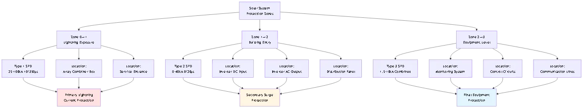
La comprensione dei tipi di SPD è essenziale per una scelta corretta. La classificazione determina dove i dispositivi devono essere installati e quale livello di protezione offrono.
Caratteristiche primarie:
Gli SPD di tipo 1 gestiscono la corrente di fulmine diretta con capacità di scarica da 25kA a 100kA (forma d'onda 10/350μs). Si installano tra le linee aeree e il quadro di distribuzione principale, progettati per il primo punto di protezione dell'edificio.
Costruzione: Componenti per impieghi gravosi, tra cui spinterometri o tubi a scarica di gas combinati con MOV. Dimensioni fisiche elevate (spesso più di 6 pollici di altezza) per soddisfare i requisiti di assorbimento di energia.
Livello di protezione della tensione: In genere 1,5-2,5kV per i sistemi a 230 V CA, 2,5-4,0kV per i sistemi a 600 V CC.
Luogo di installazione: Pannello di ingresso del servizio, quadro di distribuzione principale o scatole di combinatori di campi solari in zone esposte direttamente ai fulmini.
Intervallo di costo: $200-$800 per dispositivo, a seconda della corrente nominale di scarica e del numero di elementi di protezione.
✅ Quando è richiesto:
- Impianti fotovoltaici a terra esposti a colpi diretti
- Protezione dell'ingresso di servizio secondo NEC 230.67 (facoltativa ma consigliata)
- Aree ad alto rischio di fulminazione (>25 fulmini/km²/anno)
- Sistemi con conduttori di servizio aerei in c.a. o c.c.
❌ Non necessario Quando:
- Impianti sul tetto di edifici con protezione antifulmine a livello di edificio esistente
- Aree urbane a basso rischio di fulminazione con servizio sotterraneo
- Piccoli impianti residenziali sotto i 10kW in zone a rischio standard
Caratteristiche primarie:
Gli SPD di tipo 2 proteggono dalle sovratensioni condotte con capacità di scarica da 8kA a 40kA (forma d'onda 8/20μs). Si installano sui quadri di distribuzione e sulle apparecchiature critiche, come gli inverter.
Costruzione: Tecnologia a varistore in ossido di metallo (MOV) in alloggiamenti compatti. Più dischi MOV in serie/parallelo forniscono la tensione e la corrente nominale desiderate.
Livello di protezione della tensione: In genere 1,2-2,0kV per i sistemi a 230 V CA, 1,8-3,0kV per i sistemi a 600 V CC (inferiore al tipo 1).
Luogo di installazione: Terminali di ingresso CC dell'inverter, uscita CA dell'inverter, pannelli di sottodistribuzione, pannelli di carico critici.
Intervallo di costo: $80-$400 per dispositivo, a seconda della tensione nominale e del numero di poli.
✅ Applicazioni standard:
- Sistemi solari residenziali su tetto (requisito minimo NEC 690.35)
- Protezione dell'ingresso CC dell'inverter
- Protezione dell'uscita CA dell'inverter
- Protezione CC del sistema di batterie
🎯 Suggerimento professionale: Gli SPD di tipo 2 devono essere installati il più vicino possibile all'apparecchiatura protetta, possibilmente entro 30 cm (12 pollici), per ridurre al minimo la sovratensione dovuta all'induttanza dei conduttori. I cavi di collegamento più lunghi riducono notevolmente l'efficacia dell'SPD.
Caratteristiche primarie:
Gli SPD di tipo 3 forniscono una protezione definitiva per i dispositivi elettronici sensibili con capacità di scarica da 1,5kA a 10kA (onda combinata). Si installano direttamente sui terminali delle apparecchiature o all'interno dei dispositivi.
Costruzione: Piccoli componenti MOV o diodi soppressori di tensione transitoria (TVS) ottimizzati per un tempo di risposta rapido (<25 nanoseconds) rather than high current capacity.Livello di protezione della tensione:. In genere 0,8-1,5kV per i sistemi a 230 V CA, 1,2-2,0kV per i circuiti CC (tensione di serraggio più bassa).
Luogo di installazione: Apparecchiature di monitoraggio, linee di comunicazione, circuiti di controllo, connessioni di carichi individuali.
Intervallo di costo: $30-$150 per dispositivo per correnti nominali ridotte.
✅ Usi specializzati:
- Protezione della linea di comunicazione RS485 per i sistemi di monitoraggio
- Protezione della comunicazione Ethernet/WiFi per il monitoraggio dell'inverter
- Protezione del sensore e del circuito di controllo
- Protezione delle apparecchiature ad alta sensibilità dopo il coordinamento di tipo 1+2
❌ Non può essere sostituito: Gli SPD di tipo 3 non hanno la capacità energetica necessaria per fungere da protezione primaria contro le sovratensioni e devono sempre essere utilizzati insieme a dispositivi di tipo 1 o 2.
| Parametro | Basso rischio Ng <10 | Rischio moderato Ng 10-25 | Alto rischio Ng >25 |
|---|---|---|---|
| Protezione lato CC | Tipo 2 20kA (8/20µs) | Tipo 2 40kA (8/20µs) | Tipo 1+2 50kA (10/350µs) |
| Protezione laterale CA | Tipo 2 20kA monofase | Tipo 2 40kA monofase | Tipo 2 65kA monofase |
| Protezione della comunicazione | Tipo 3 Se si utilizza il monitoraggio | Tipo 3 Consigliato | Tipo 3 Richiesto |
| Punti di installazione | 1-2 posizioni | 2-3 posizioni | 3-4 posizioni |
| Costo totale della protezione | $200-$500 | $500-$1,200 | $1,200-$2,500 |
Dettagli della configurazione:
Sistemi a basso rischio:
- SPD singolo di tipo 2 all'ingresso DC dell'inverter (spesso integrato in inverter di qualità)
- SPD di tipo 2 opzionale sul pannello principale CA
- Protezione minima della comunicazione, a meno che non si tratti di un monitoraggio di alto valore
Sistemi a rischio moderato:
- SPD di tipo 2 all'ingresso CC dell'inverter (portata 40kA)
- SPD di tipo 2 sull'uscita CA dell'inverter
- SPD di tipo 3 su linee di monitoraggio RS485 o Ethernet
- Messa a terra potenziata con Resistenza <10ΩSistemi ad alto rischio:
- SPD combinato di tipo 1 o 1+2 sul combinatore di campo se montato a terra
- SPD di tipo 2 all'ingresso DC dell'inverter (coordinato con il tipo 1)
- SPD di tipo 2 sull'uscita CA dell'inverter e sul pannello principale
- SPD di tipo 3 su tutti i circuiti di comunicazione
| Elemento di protezione | Specifiche minime | Specifiche raccomandate | Specifica Premium |
|---|---|---|---|
| Combinatore CC SPD | Tipo 2, 40kA secondo IEC 61643-11 | Tipo 1+2, 50kA 12,5kA Iimp | Tipo 1, 100kA 25kA Iimp |
| Ingresso CC dell'inverter | Tipo 2, 20kA per stringa | Tipo 2, 40kA coordinato | Tipo 2, 65kA con indicatore remoto |
| Distribuzione CA | Tipo 2, 40kA 3-fase | Tipo 2, 65kA 3 fasi + neutro | Tipo 1, 100kA coordinamento completo |
| Comunicazione/Dati | Tipo base 3 solo linee dati | Tipo 3 tutti i circuiti con schermatura | Tipo coordinato 2+3 monitoraggio completo |
| Caratteristiche di monitoraggio | Indicatori visivi solo | Allarme remoto contatti | Integrazione SCADA avvisi predittivi |
| Costo del sistema | $1,500-$3,000 | $3,000-$6,000 | $6,000-$12,000 |
Linee guida per la selezione:
Scegliere Minimo specifiche per:
- Zone a rischio standard (Ng 10-20)
- Array su tetti di edifici con protezione antifulmine esistente
- Progetti con budget limitato e requisiti assicurativi di base
Scegliere Consigliato specifiche per:
- La maggior parte delle installazioni commerciali (standard industriale)
- Zone a rischio moderato-alto (Ng 20-30)
- Sistemi che richiedono la documentazione di conformità assicurativa
Scegliere Premio specifiche per:
- Strutture critiche di alto valore
- Zone ad alto rischio di fulminazione (Ng >30)
- Sistemi con garanzie estese che richiedono una protezione completa
- Strutture che richiedono la massima operatività (ospedali, centri dati)

Tensione massima di funzionamento continuo (MCOV/Uc):
Si tratta della tensione continua più alta che l'SPD può sopportare senza condurre. Scegliere una MCOV pari ad almeno 1,15× la Voc del sistema (tensione a circuito aperto) per evitare che si inneschino fastidiosi aumenti di tensione durante le stagioni fredde.
Formula di selezione:
MCOV ≥ (Voc × 1,15) + margine di sicurezza
Esempio di calcolo:
- Sistema: 16 pannelli × 42V Voc = 672V di tensione di stringa
- MCOV minimo: 672V × 1,15 = 773V
- SPD selezionato: MCOV = 800V o 1000V standard
- Non utilizzare mai: SPD 600V MCOV (si guasterebbe con il normale funzionamento)
⚠️ Avvertenze: L'utilizzo di un SPD con MCOV insufficiente causa un guasto prematuro. Il dispositivo conduce durante le normali condizioni di alta tensione (mattine fredde), degradando rapidamente gli elementi MOV e causando un guasto aperto o un cortocircuito.
Livello di protezione della tensione (Up):
Specifica la tensione massima che appare sui terminali dell'SPD durante le sovratensioni. Una tensione inferiore è migliore per la protezione delle apparecchiature.
Valori tipici per tipo:
- SPD DC di tipo 1: Fino a = 2,5-4,0kV (sistemi a 1000V)
- SPD CC di tipo 2: Fino = 1,8-3,0kV (sistemi a 1000V)
- SPD CC di tipo 3: Fino a = 1,2-2,0kV (sistemi a 1000V)
Verifica della compatibilità delle apparecchiature:
Verificare che il grado di immunità alle sovratensioni dell'inverter superi il livello di protezione dell'SPD. La maggior parte degli inverter moderni resiste a un'immunità alle sovratensioni di 4-6kV, fornendo un margine adeguato con gli SPD di tipo 2 (fino a ≈ 2,5kV).
Corrente di scarica nominale (In):
Corrente nominale utilizzata per la classificazione e il test. Gli SPD di tipo 2 hanno in genere una corrente nominale di 20kA, 40kA o 65kA (forma d'onda 8/20μs).
Selezione per livello di rischio:
- Basso rischio (Ng <10): 20kA sufficienti per gli array su tetto
- Rischio moderato (Ng 10-25): 40kA raccomandati
- Alto rischio (Ng >25): 65kA o Tipo 1 (100kA) richiesto
Corrente di scarica massima (Imax):
La corrente di sovracorrente più alta che l'SPD può gestire senza guasti. In genere 1,5-2 volte il valore nominale.
Per i DOCUP di tipo 1, la specifica critica è Iimp (corrente impulsiva) utilizzando una forma d'onda di 10/350μs, misurando la capacità di fulminazione diretta. Minimo 12,5kA Iimp per gli array esposti, 25kA per le installazioni ad alto rischio.
Tempo di risposta (<25ns per gli SPD basati su MOV):
La velocità con cui l'SPD inizia a condurre dopo la comparsa della sovratensione. Risposta rapida (<50ns) è fondamentale per proteggere l'elettronica sensibile dell'inverter.
La tecnologia MOV offre la risposta più rapida. I tubi a scarica di gas (GDT) hanno una risposta più lenta (100ns-1μs) ma una capacità energetica più elevata; spesso vengono utilizzati in combinazione con i MOV per le applicazioni di tipo 1.
Corrente di passaggio:
La quantità di corrente di sovratensione che passa attraverso l'SPD fino alle apparecchiature protette. Gli SPD di qualità limitano il passaggio a <1% di corrente di sovratensione grazie a un corretto adattamento dell'impedenza.
Valutazione dell'involucro:
- Inverter per interni: IP20 minimo (NEMA 1)
- Scatole combinatore per esterni: IP65 minimo (NEMA 3R)
- Ambienti difficili: IP66/IP67 (NEMA 4X)
Intervallo di temperatura:
Gli SPD standard funzionano da -40°C a +85°C. Verificare che l'intervallo di funzionamento corrisponda all'ambiente di installazione: gli inverter montati in soffitta possono superare i 70°C ambientali.
Riduzione dell'altitudine:
Gli SPD perdono efficacia ad alta quota a causa della ridotta rigidità dielettrica dell'aria. Applicare un declassamento della tensione 1% per 100 m di altitudine oltre i 1000 m.
L'installazione di più SPD in posizioni diverse crea una cascata di protezione. Senza un adeguato coordinamento, gli SPD interagiscono in modo distruttivo anziché cooperativo, consentendo potenzialmente a un dispositivo di guastarsi mentre gli altri non si attivano.
Tre fattori di coordinamento:
1. Condivisione dell'energia: Gli SPD correttamente coordinati condividono l'energia di sovratensione in modo proporzionale in base all'impedenza e alla distanza.
2. Firma di tensione: Ogni SPD deve bloccare alla tensione appropriata per garantire l'attivazione della cascata.
3. Distanza di installazione: Separazione minima richiesta tra i tipi di SPD per un funzionamento corretto
Quando si utilizzano SPD di tipo 1 e 2 nello stesso sistema, mantenere la distanza minima di separazione per il disaccoppiamento induttivo.
Requisiti minimi di separazione:
- Lunghezza del cavo >10 metri: Non è necessario alcun coordinamento aggiuntivo
- 5-10 metri: Utilizzare l'impedenza in serie (induttore/resistore)
- <5 metri: Utilizzare set SPD coordinati dello stesso produttore
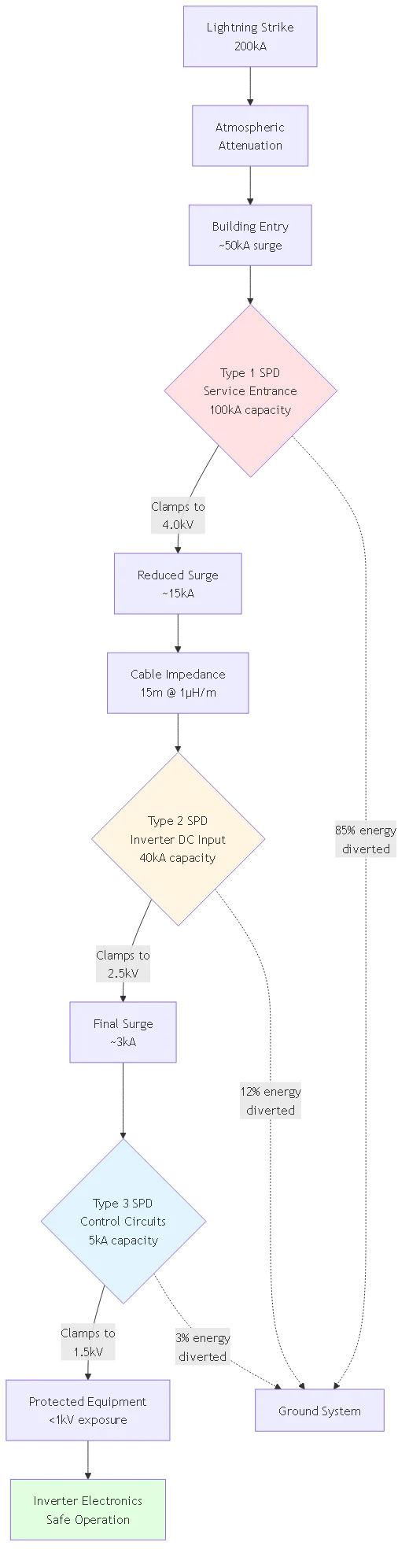
Esempio di configurazione:
- SPD di tipo 1 sulla scatola del combinatore di campo (esposto agli urti diretti)
- 15 metri di cavo fino all'inverter
- SPD di tipo 2 all'ingresso CC dell'inverter
- Risultato: La corretta separazione consente al tipo 1 di gestire le sovratensioni primarie, mentre il tipo 2 fornisce il bloccaggio a livello di apparecchiature.
La protezione fine per le apparecchiature di monitoraggio e controllo sensibili richiede il tipo 2 a monte e il tipo 3 ai terminali del dispositivo.
Applicazione tipica:
- SPD di tipo 2 sui terminali DC dell'inverter principale (capacità 40kA)
- SPD di tipo 3 sulla scheda di comunicazione dell'inverter (capacità 5kA)
- Separazione: 2-3 metri di cablaggio interno dell'inverter forniscono un disaccoppiamento adeguato
- Livello di protezione: Il tipo 2 riduce la sovracorrente di 10kA a 2,5kV, il tipo 3 blocca ulteriormente a 1,5kV per i circuiti sensibili.
🎯 Suggerimento professionale: Specificare sempre il coordinamento degli SPD come sistema, non come singoli dispositivi. Molti produttori offrono set di SPD precoordinati con compatibilità testata e istruzioni di installazione. In questo modo si eliminano i requisiti di calcolo del coordinamento e si garantisce il corretto funzionamento.
Ogni metro di filo tra l'SPD e l'apparecchiatura protetta aggiunge induttanza che riduce l'efficacia della protezione. I cavi lunghi generano un sovraccarico di tensione che vanifica la funzione di bloccaggio dell'SPD.
Impatto dell'induttanza del conduttore:
Induttanza del filo ≈ 1μH per metro
Superamento della tensione = L × (dI/dt)
Per una sovracorrente di 10kA con tempo di salita di 8μs:
- Cavi da 0,3 m: ~375V overshoot (accettabile)
- Conduttori da 1,0 m: ~1.250V di sovraelongazione (marginale)
- Cavi da 3,0 m: ~3.750V overshoot (protezione inefficace)
Regole di installazione:
Ideale: SPD montato direttamente sui terminali dell'apparecchiatura protetta con <30cm total lead length (positive + negative ground).Accettabile.: Conduttori inferiori a 1,0 m utilizzando il massimo calibro di filo (minimo 6 AWG).
Evitare: Conduttori superiori a 1,5 m: considerare la possibilità di riposizionare l'SPD più vicino all'apparecchiatura o di utilizzare un SPD remoto con isolamento in fibra ottica.
Instradamento dei conduttori: Utilizzare una configurazione a coppie intrecciate o far passare i conduttori positivo/negativo in stretto parallelo per ridurre al minimo l'induttanza del loop. Non creare mai anelli di filo di grandi dimensioni.
Gli SPD deviano la corrente di sovratensione verso terra: una messa a terra inadeguata li rende inefficaci, indipendentemente dalla qualità del dispositivo.
Requisiti di messa a terra:
Resistenza di terra: Raggiungere <10Ω misurato dal terminale di terra dell'SPD alla terra. Più basso è meglio; obiettivo <5Ω per installazioni SPD di tipo 1.Dimensionamento del conduttore di terra: Rame minimo 6 AWG per gli SPD residenziali di Tipo 2, 4 AWG per le installazioni commerciali, 2 AWG o superiore per le applicazioni di Tipo 1.
Metodo di connessione: Utilizzare capicorda a compressione o connettori meccanici elencati e non affidarsi mai a dadi metallici o collegamenti a spirale per la messa a terra degli SPD.
Legame equipotenziale: Collegare la messa a terra dell'SPD al sistema di elettrodi di messa a terra principale, insieme ai telai dei pannelli, alle scaffalature e alle guaine metalliche. Molteplici messe a terra separate creano pericolosi loop di terra.
⚠️ Avvertenze: Per testare la resistenza di terra è necessario un apposito tester di resistenza di terra a 3 o 4 fili. I multimetri standard non sono in grado di misurare con precisione la resistenza di terra. La scarsa messa a terra è la #1 causa di guasto della protezione SPD.
Gli SPD si sacrificano per proteggere le apparecchiature. Senza monitoraggio, gli SPD guasti rimangono installati e forniscono una falsa sicurezza.
Tipi di indicatori:
Bandiera meccanica: La bandiera rossa/verde visibile indica lo stato operativo dell'SPD. È il più affidabile, ma richiede un'ispezione visiva.
Indicatore LED: Le luci verdi/rosse indicano lo stato. Richiede il collegamento all'alimentazione per funzionare, non segnala il guasto se il circuito è privo di tensione.
Contatto remoto: La chiusura del contatto pulito segnala il guasto dell'SPD al sistema di monitoraggio o al pannello di allarme. Indispensabile per i sistemi commerciali.
Sezionatore: Il sezionatore termico incorporato isola l'SPD guasto per evitare condizioni di cortocircuito. Richiesto per gli SPD di tipo 1 e 2 lato CA secondo la norma NEC 285.25.
Programma di ispezione:
- Sistemi residenziali: Controllare gli indicatori ogni 6 mesi durante la manutenzione ordinaria
- Sistemi commerciali: Controllo visivo mensile o monitoraggio remoto continuo
- Dopo un evento di sovratensione noto: Ispezione e test immediati
- Annuale: Test professionale con misuratore di megaohm per verificare l'integrità del MOV
Problema: Gli elettricisti che hanno dimestichezza con i lavori elettrici di costruzione, ma che sono alle prime armi con l'energia solare, utilizzano i dispositivi di protezione contro le sovratensioni standard in corrente alternata sui circuiti in corrente continua, perché “hanno la stessa tensione”.”
Perché non funziona: Gli archi di corrente alternata e di corrente continua si comportano in modo fondamentalmente diverso. La corrente alternata attraversa lo zero 120 volte al secondo, estinguendo naturalmente gli archi. Gli archi in c.c. si mantengono in modo continuo: una volta che un arco elettrico si accende in un dispositivo a corrente alternata in c.c., non si autoestingue e può provocare incendi.
Scenari comuni:
- Utilizzo di soppressori di sovratensione dell'edificio all'ingresso CC dell'inverter solare
- Installazione di SPD in c.a. in scatole combinatore in c.c.
- Specificare gli scaricatori di corrente standard per applicazioni in c.c.
Correzione: Specificare sempre SPD classificati per la corrente continua con certificazione UL 1449 DC o IEC 61643-11. Verificare che il valore MCOV sia superiore a Voc del sistema × 1,15. I dispositivi classificati per la corrente continua utilizzano una struttura interna e materiali diversi per interrompere in modo sicuro gli archi in corrente continua.
Problema: Specificare SPD MCOV da 600 V per sistemi solari da 600 V senza tenere conto della tensione a circuito aperto superiore ai valori nominali.
Perché non funziona: Un “sistema solare a 600 V” funziona in realtà a 700-750 V di tensione a circuito aperto (a freddo). L'SPD conduce continuamente a queste tensioni normali, degradando rapidamente i MOV e fallendo nel giro di pochi mesi.
Scenari comuni:
- Corrispondenza della tensione SPD alla tensione MPP dell'inverter anziché alla Voc
- Ignorare il coefficiente di temperatura (aumento della tensione a freddo)
- Utilizzo delle rimanenti scorte di SPD da sistemi a 48V su sistemi a 600V
Correzione: Calcolare la massima Voc possibile: (numero di pannelli) × (Voc del singolo pannello) × (fattore di temperatura fredda 1,05-1,10). Selezionare un SPD MCOV di almeno 1,15× questa tensione calcolata. Scelte standard: 800V o 1000V MCOV per sistemi da 600V nominali.
Problema: Gli appaltatori installano gli SPD ma non verificano o aggiornano i sistemi di messa a terra, lasciando percorsi di terra inadeguati per la dissipazione della corrente di sovratensione.
Perché non funziona: Per funzionare, gli SPD hanno bisogno di percorsi a bassa impedenza verso terra. Un'elevata resistenza a terra (>25Ω) o conduttori di terra lunghi e sovradimensionati impediscono un'efficace deviazione della corrente di sovratensione. L'energia di sovratensione non ha un posto dove andare e danneggia comunque le apparecchiature nonostante la presenza dell'SPD.
Scenari comuni:
- Installazione dell'SPD ma non test della resistenza di terra
- Utilizzo di un cavo di messa a terra da 10 AWG invece del minimo richiesto di 6 AWG
- Collegamento della terra dell'SPD alla barra di terra isolata invece che alla terra principale del sistema
- Creazione di loop di terra con più punti di terra separati
Correzione: Prima di installare gli SPD, verificare la resistenza di terra con un tester a 3 fili adeguato. <10Ω. Utilizzare conduttori di terra di almeno 6 AWG (4 AWG per il settore commerciale). Mantenere i conduttori il più corti possibile (<1m). Collegare al sistema di elettrodi di messa a terra principale condiviso con i pannelli, le scaffalature e la messa a terra delle apparecchiature.
Problema: L'installazione di più SPD in posizioni diverse senza garantire un adeguato coordinamento tra i dispositivi, fa sì che un SPD si guasti mentre gli altri non si attivano.
Perché non funziona: Gli SPD non coordinati competono per la corrente di sovratensione in base alla posizione dell'installazione e all'impedenza. L'SPD “sbagliato” può attivarsi per primo, superando la sua capacità, mentre i dispositivi a valle con capacità maggiore non si attivano mai.
Scenari comuni:
- Installazione di SPD di tipo 2 sia sulla scatola del combinatore che sull'inverter con una separazione insufficiente
- Miscelazione di SPD di produttori diversi senza verifica del coordinamento
- Posizionare i DOCUP di tipo 1 e 2 troppo vicini (<5m)Correzione: Mantenere una distanza minima di 10 m tra gli SPD di tipo 1 e 2 per un disaccoppiamento induttivo naturale. Se è necessaria un'installazione più ravvicinata, utilizzare set di SPD coordinati di un unico produttore o aggiungere un'impedenza in serie (induttore 10-20μH). Specificare sempre il coordinamento degli SPD quando si progettano sistemi con più punti di protezione.
Problema: Installare SPD CC e CA ma lasciare le linee di comunicazione (Ethernet, RS485, WiFi) non protette, consentendo l'ingresso di sovratensioni attraverso i sistemi di monitoraggio.
Perché non funziona: La corrente di sovratensione trova tutte le vie di accesso alle apparecchiature. Gli inverter moderni hanno più punti di connessione: terminali di alimentazione e porte di comunicazione. Le tensioni indotte dai fulmini si accoppiano ai cavi di comunicazione con la stessa facilità dei cavi di alimentazione.
Scenari comuni:
- Protezione dell'inverter DC/AC ma non della connessione di monitoraggio Ethernet
- Lasciare la catena daisy-chain RS485 tra gli inverter senza protezione
- Utilizzo di punti di accesso WiFi esterni senza protezione da sovratensioni
Correzione: Installare SPD di tipo 3 su tutti i circuiti di comunicazione che entrano negli inverter e nelle apparecchiature di monitoraggio. Utilizzare cavi schermati per i percorsi di comunicazione superiori a 10 m. Mettere a terra gli schermi dei cavi a entrambe le estremità fino al telaio dell'apparecchiatura. Considerare l'isolamento della fibra ottica per i percorsi di comunicazione superiori a 50 m in aree ad alto rischio.
Esempio di sistema residenziale (10kW, rischio moderato):
Rischio di sistema non protetto:
- 20% probabilità di sovratensioni dannose in 25 anni
- Costo medio del danno: $4.500 (inverter + chiamata di assistenza + tempo di inattività)
- Valore di perdita previsto: $900 nel corso della vita del sistema
Protezione SPD Investimento:
- SPD tipo 2 CC + CA: $400 installato
- Sostituzione SPD prevista (2×): $200
- Costo totale della protezione: $600
Risultato: $300 risparmi netti, oltre alla tranquillità e alla protezione della garanzia. Una protezione economicamente giustificata anche in scenari di rischio moderato.
Esempio di sistema commerciale (150 kW, rischio elevato):
Rischio di sistema non protetto:
- 40% probabilità di sovratensione dannosa nell'arco di 25 anni
- Costo medio dei danni: $18.000 (inverter multipli + perdita di produzione)
- Valore di perdita previsto: $7.200 nel corso della vita del sistema
Protezione SPD potenziata Investimento:
- Sistema coordinato di tipo 1+2: $4.500 installati
- Manutenzione e sostituzione: $1.500
- Costo totale della protezione: $6.000
- Riduzione dei premi assicurativi: -$2.000 (5% di riduzione annuale)
- Costo netto: $4.000
Risultato: $3.200 risparmi netti, oltre a evitare interruzioni dell'attività e conformità assicurativa. Una forte giustificazione economica per una protezione completa.
| Dimensione del sistema | Costo della protezione | Danno previsto (Non protetto) | Break-Even Probabilità | Decisione economica |
|---|---|---|---|---|
| 5kW Residenziale | $300-$500 | $2,500-$4,000 | 10-15% | Marginale, conformità al codice |
| 10kW Residenziale | $400-$800 | $3,500-$6,000 | 8-12% | Giustificato con Ng >10 |
| 50kW Commerciale | $1,500-$3,000 | $8,000-$15,000 | 12-18% | Fortemente giustificato |
| 200kW Commerciale | $4,000-$8,000 | $20,000-$40,000 | 15-25% | Protezione essenziale |
| 1MW+ Utilità | $25,000-$100,000 | $100,000-$500,000 | 20-30% | Richiesto per il finanziamento |
Approfondimento chiave: L'economia della protezione SPD migliora notevolmente con le dimensioni del sistema. Le grandi installazioni commerciali e di pubblica utilità dovrebbero sempre investire in una protezione coordinata completa: il ROI è evidente anche nelle zone a rischio moderato.
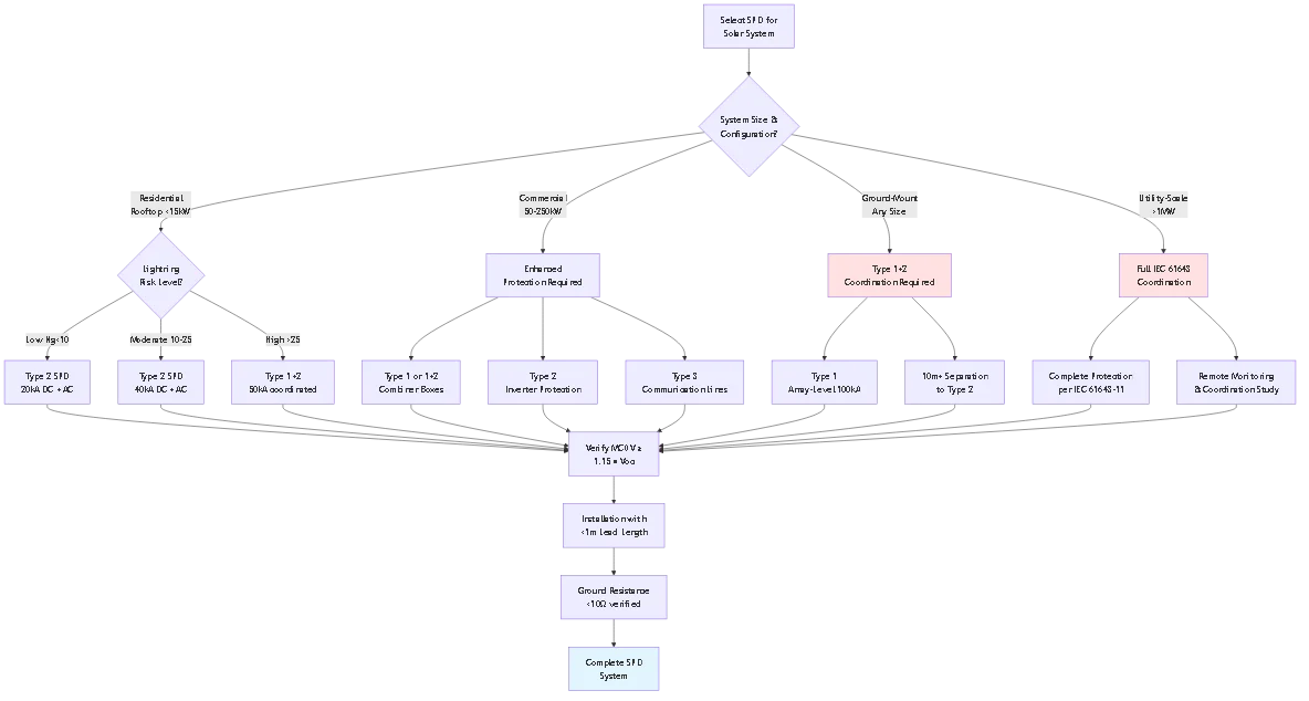
NEC Articolo 690.35 richiede dispositivi di protezione contro le sovratensioni (SPD) sugli impianti fotovoltaici non collegati a terra, con SPD di tipo 2 come livello di protezione minimo accettabile per la maggior parte delle installazioni. I requisiti specifici dipendono dalla configurazione del sistema e dal rischio di fulminazione locale.
Per i sistemi residenziali standard su tetto di potenza inferiore a 15kW in aree a rischio moderato, un SPD di tipo 2 con corrente di scarica di 20-40kA all'ingresso CC dell'inverter soddisfa i requisiti del codice. L'SPD deve essere classificato come DC con una tensione massima di funzionamento continuo (MCOV) superiore a 1,15 volte la tensione a circuito aperto del sistema. I sistemi commerciali superiori a 50kW richiedono in genere una protezione coordinata di tipo 1+2 con SPD sia sulle scatole di combinatori che sugli inverter. Gli impianti montati a terra in qualsiasi luogo necessitano di una protezione maggiore, compresi gli SPD di Tipo 1, a causa della maggiore esposizione ai fulmini. L'SPD scelto deve avere l'elenco UL 1449 DC o la certificazione equivalente IEC 61643-11 che conferma l'idoneità per le applicazioni solari DC.
La scelta tra gli SPD di Tipo 1 e di Tipo 2 dipende principalmente dal luogo di installazione e dal livello di esposizione ai fulmini. Gli SPD di Tipo 1 (Classe I) sono progettati per la protezione primaria degli ingressi di servizio e dei luoghi esposti a fulmini diretti, con capacità di scarica di 25-100kA utilizzando la forma d'onda 10/350μs che simula i fulmini diretti.
Gli SPD di Tipo 2 (Classe II) forniscono una protezione secondaria a livello delle apparecchiature con una capacità di 8-40kA utilizzando la forma d'onda 8/20μs che rappresenta le sovratensioni condotte. Scegliere gli SPD di Tipo 1 per: impianti solari montati a terra in campo aperto, scatole di combinazione degli impianti su strutture esposte, protezione degli ingressi di servizio in zone ad alto rischio (>25 fulmini/km²/anno) e qualsiasi installazione che richieda protezione contro la corrente di fulmine diretta. Selezionare gli SPD di Tipo 2 per: array residenziali su tetto di edifici, protezione dell'ingresso DC dell'inverter, protezione dell'uscita AC dell'inverter e pannelli di sottodistribuzione. Molte installazioni commerciali utilizzano entrambi i tipi in configurazione coordinata: il tipo 1 sulla scatola del combinatore per gestire potenziali fulmini diretti, seguito dal tipo 2 sull'inverter per la protezione a livello di apparecchiatura con un bloccaggio di tensione inferiore.
No, non si devono mai utilizzare dispositivi di protezione da sovratensioni in corrente alternata sui circuiti solari in corrente continua, a causa delle differenze fondamentali nel comportamento degli archi elettrici in corrente alternata e in corrente continua. La corrente alternata attraversa naturalmente lo zero di tensione 120 volte al secondo, il che aiuta a spegnere automaticamente gli archi elettrici. La corrente continua mantiene una polarità costante senza attraversamenti dello zero, il che significa che una volta che un arco elettrico inizia in un dispositivo classificato per la corrente alternata che funziona in corrente continua, non può autoestinguersi e può portare a un guasto o a un incendio del dispositivo.
I dispositivi di protezione contro le sovratensioni in CA utilizzano componenti interni e valori nominali basati sulle caratteristiche di interruzione dell'arco in CA. Se sottoposti a tensione continua, questi dispositivi possono inizialmente sembrare funzionanti, ma si guastano in modo catastrofico durante gli eventi di sovratensione reali, quando si sviluppano archi continui di corrente continua. Per le applicazioni solari, specificare sempre SPD classificati per la corrente continua con certificazione UL 1449 DC o IEC 61643-11. Gli SPD classificati per la corrente continua utilizzano una struttura interna diversa, camere di spegnimento dell'arco migliorate e materiali specificamente progettati per interrompere in modo sicuro gli archi in corrente continua prolungati. Anche la tensione nominale è fondamentale: assicuratevi che la tensione massima di funzionamento continuo (MCOV) dell'SPD superi la tensione a circuito aperto del vostro sistema di almeno 15% per evitare un funzionamento fastidioso durante i normali picchi di tensione nelle stagioni fredde.
Gli intervalli di sostituzione degli SPD dipendono dalla frequenza di esposizione alle sovratensioni, dalla qualità del dispositivo e dalle capacità di monitoraggio, piuttosto che da scadenze fisse. Gli SPD di qualità di tipo 2 nelle applicazioni residenziali durano in genere 5-15 anni in assenza di sovratensioni importanti, ma i dispositivi esposti a sovratensioni minori frequenti possono degradarsi entro 3-5 anni.
La chiave è monitorare lo stato di salute dell'SPD piuttosto che ipotizzare una sostituzione basata sul calendario. I moderni SPD includono indicatori di fine vita - bandiere visive, luci LED o contatti di allarme remoti - che segnalano quando il dispositivo si è sacrificato per proteggere le apparecchiature e deve essere sostituito. Controllare questi indicatori ogni 6 mesi durante la manutenzione ordinaria. Dopo un fulmine o una perturbazione della rete nota nelle vicinanze che fa scattare gli interruttori, ispezionare immediatamente tutti gli indicatori SPD. Sostituire immediatamente gli SPD che mostrano un'indicazione di guasto: gli SPD guasti non forniscono alcuna protezione. Per i sistemi commerciali, implementare il monitoraggio continuo a distanza dello stato degli SPD tramite SCADA o sistemi di gestione degli edifici, consentendo di programmare immediatamente la sostituzione. Anche se gli indicatori mostrano uno stato “buono”, considerate la sostituzione degli SPD ogni 8-10 anni come manutenzione preventiva nelle aree ad alto rischio, in quanto gli elementi MOV possono degradarsi internamente senza indicazioni esterne visibili. Tenere a magazzino gli SPD di ricambio per le strutture critiche per ridurre al minimo i tempi di inattività quando è necessaria la sostituzione.
Le modalità di guasto degli SPD dipendono dal tipo di dispositivo e dalla presenza di sezionatori termici. Gli SPD di qualità di tipo 2 e 3 in genere si guastano “a circuito aperto”: smettono di condurre e non forniscono ulteriore protezione, ma non creano cortocircuiti o rischi di incendio. Il sistema solare continua a funzionare normalmente senza protezione.
Gli SPD di tipo 1 e alcuni dispositivi di tipo 2 ad alta corrente possono andare in “cortocircuito” se non dispongono di sezionatori termici adeguati, creando potenzialmente un guasto a terra che fa scattare gli interruttori o provoca condizioni di sovracorrente. Per questo motivo, la norma NEC 285.25 richiede sezionatori per gli SPD installati sul lato del carico della protezione contro le sovracorrenti all'ingresso del servizio. Gli SPD guasti senza sezionatori possono surriscaldarsi o incendiarsi in caso di cortocircuito. Il pericolo di un guasto all'SPD non è il danno immediato al sistema, ma la perdita di protezione contro i successivi eventi di sovracorrente. Un SPD a circuito aperto guasto lascia l'apparecchiatura completamente vulnerabile al prossimo fulmine o alla sovracorrente, che potrebbe distruggere inverter e dispositivi elettronici del valore di migliaia di dollari. Ecco perché il monitoraggio della fine del ciclo di vita degli SPD è fondamentale. Installate SPD con indicatori visibili (luci LED o bandiere meccaniche) e controllateli regolarmente. Per i sistemi commerciali, utilizzare SPD con contatti di allarme remoti collegati ai sistemi di monitoraggio per una notifica immediata del guasto. Sostituire immediatamente gli SPD guasti per ripristinare la protezione: continuare a funzionare con SPD guasti è come guidare senza assicurazione dopo un incidente.
Sì, una protezione completa del sistema solare richiede SPD separati sia sul lato CC che su quello CA, perché ogni lato è esposto a minacce di sovratensione diverse e opera a tensioni diverse. Gli SPD sul lato CC proteggono il campo fotovoltaico, il cablaggio CC e l'ingresso CC dell'inverter dalle sovratensioni che si originano dai pannelli solari, in particolare dalle tensioni indotte dai fulmini che si accoppiano al campo e dai fulmini vicini.
Gli SPD lato CA proteggono l'uscita CA dell'inverter, il cablaggio di distribuzione e i carichi collegati dalle sovratensioni provenienti dalla rete elettrica: fulmini sulle linee, commutazione dei trasformatori e condizioni di guasto. L'inverter fornisce un certo isolamento tra i lati CC e CA, ma l'energia di sovratensione può comunque passare attraverso la capacità parassita, i circuiti di controllo e i sistemi di messa a terra. L'installazione di SPD solo sul lato CC lascia l'elettronica CA dell'inverter vulnerabile alle sovratensioni sul lato dell'utenza, mentre la protezione solo CA non affronta i rischi più frequenti di sovratensione sul lato CC dovuti all'esposizione dell'array. Le specifiche per una protezione adeguata comprendono: SPD DC di tipo 2 all'ingresso DC dell'inverter con valore nominale di Voc del sistema, SPD AC di tipo 2 all'uscita AC dell'inverter con valore nominale di tensione di rete (monofase o trifase) e SPD di tipo 3 sui circuiti di comunicazione (Ethernet, RS485) se sono installati sistemi di monitoraggio. L'investimento totale per la protezione residenziale a tre punti è in genere di $400-$800 installato - un investimento modesto rispetto a $5.000-$15.000 delle apparecchiature da proteggere.
La selezione della tensione nominale dell'SPD richiede il calcolo della massima tensione a circuito aperto possibile del sistema e l'aggiunta di un margine di sicurezza per garantire che l'SPD non si attivi durante il normale funzionamento. La specifica fondamentale è MCOV (tensione operativa massima continua), ovvero la tensione CC più alta che l'SPD può sopportare in modo continuo senza degradarsi.
Calcolare l'MCOV richiesto utilizzando la seguente formula: MCOV ≥ (numero di pannelli in serie) × (Voc del singolo pannello) × (coefficiente di temperatura 1,05-1,10) × (fattore di sicurezza 1,15). Ad esempio, una stringa con 20 pannelli da 42V Voc ciascuno: Voc massima = 20 × 42V × 1,08 (temperatura fredda) = 907V; MCOV minimo = 907V × 1,15 = 1.043V; Selezionare l'SPD standard: 1.000V o 1.200V di MCOV. I sistemi residenziali più comuni (600V nominali) richiedono SPD da 800V o 1.000V MCOV. Non utilizzare mai SPD con MCOV inferiore al fabbisogno calcolato: gli SPD sovradimensionati si comportano in condizioni normali di alta tensione (mattine fredde, a vuoto), deteriorando rapidamente gli elementi MOV e guastandosi nel giro di pochi mesi. Dopo l'MCOV, verificare che il livello di protezione dalla tensione (Up) sia compatibile con il grado di immunità alle sovratensioni dell'inverter: la maggior parte degli inverter moderni resiste a 4-6kV, fornendo un margine adeguato con SPD di tipo 2 con valori Up ≈ 2,5kV. In caso di dubbio, scegliere il valore di tensione standard immediatamente superiore piuttosto che rischiare di avere una protezione sottodimensionata.
Un'efficace protezione dalle sovratensioni per gli impianti solari richiede la selezione sistematica di SPD con un rating adeguato, in base alla configurazione dell'impianto, al rischio di fulmini e ai requisiti della normativa. L'investimento in una protezione adeguata è modesto rispetto ai costi di sostituzione delle apparecchiature e alle interruzioni operative dovute ai danni da sovratensione.
Punti di forza:
1. La conformità al codice inizia con i DOCUP di tipo 2: La norma NEC 690.35 prescrive la protezione dalle sovratensioni per gli impianti fotovoltaici non collegati a terra: gli SPD di tipo 2 in corrente continua agli ingressi degli inverter sono la protezione minima accettabile per le installazioni residenziali.
2. La tensione nominale è fondamentale: Selezionare SPD con MCOV superiore a 1,15× la tensione di circuito aperto del sistema per evitare un funzionamento anomalo durante le basse temperature: il sottodimensionamento provoca guasti prematuri.
3. Il tipo di sistema determina il livello di protezione: Gli impianti residenziali su tetto necessitano in genere di una protezione di tipo 2, i sistemi commerciali richiedono una protezione coordinata di tipo 1+2, mentre gli impianti a terra necessitano sempre di una protezione primaria di tipo 1.
4. Il coordinamento massimizza l'efficacia: Gli SPD multipli funzionano insieme solo se adeguatamente coordinati: mantenere una distanza di separazione adeguata o utilizzare set abbinati dal produttore per garantire la protezione in cascata.
5. Il monitoraggio previene i guasti silenziosi: Gli SPD si sacrificano a proteggere le apparecchiature: installare dispositivi con indicatori di fine vita e controllarli regolarmente per garantire una protezione continua.
L'approccio più efficace prevede l'implementazione di una protezione stratificata adeguata al rischio effettivo: SPD di base di tipo 2 per i sistemi residenziali a basso rischio, protezione coordinata avanzata per le installazioni commerciali e sistemi completi a più livelli per gli impianti di alto valore o ad alta esposizione. Una scelta corretta degli SPD, unita a un'installazione di qualità e a un monitoraggio regolare, garantisce una protezione affidabile per tutta la durata di vita dell'impianto (oltre 25 anni).
Risorse correlate:
- SPD DC per sistemi solari: Applicazioni di tipo 1 e di tipo 2
- Comprensione dell'SPD DC: tecnologia di protezione MOV vs GDT
- Selezione degli SPD da 1000 V CC: Protezione del sistema su scala industriale
Siete pronti a specificare la protezione dalle sovratensioni per il vostro impianto solare? Contattate il nostro team tecnico per ricevere consigli sugli SPD specifici per il sistema, in base alla configurazione dell'array, alla densità di fulmini locale e ai requisiti di protezione delle apparecchiature. Forniamo soluzioni SPD coordinate conformi a tutti gli standard NEC e IEC con una documentazione di installazione completa.
Ultimo aggiornamento: Marzo 2026
Autore: Team tecnico SYNODE
Recensito da: Dipartimento di ingegneria elettrica
Parola chiave di riferimento: Protezione dalle sovratensioni per sistemi solari
URL Slug: Guida alla selezione dei sistemi solari di protezione contro le sovratensioni
Meta Titolo: Protezione dalle sovratensioni per impianti solari: Guida completa alla selezione degli SPD 2025
Meta descrizione: Imparate a gestire la protezione dalle sovratensioni per gli impianti solari con le matrici di selezione dei tipi di SPD degli esperti. Confrontate i dispositivi di tipo 1, 2 e 3, coordinate i livelli di protezione e soddisfate i requisiti NEC 690.35.
Livello di contenuto: Livello 2 (Contenuto standard)
Funnel di conversione: Centro dell'imbuto (considerazione)
Conteggio parole obiettivo: 2800-4000 parole
Diagrammi della sirena target: 3
Configurarli nelle impostazioni di Rank Math, quindi eliminare questa casella prima della pubblicazione.
L'articolo 690.35 del NEC richiede dispositivi di protezione contro le sovratensioni (SPD) per gli impianti fotovoltaici non collegati a terra; gli SPD di tipo 2 rappresentano il livello di protezione minimo accettabile per la maggior parte delle installazioni. I requisiti specifici dipendono dalla configurazione del sistema e dal rischio di fulminazione locale. Per gli impianti residenziali standard su tetto di potenza inferiore a 15kW in aree a rischio moderato, un SPD di Tipo 2 con corrente di scarica di 20-40kA all'ingresso CC dell'inverter soddisfa i requisiti del codice. L'SPD deve essere classificato come DC con una tensione massima di funzionamento continuo (MCOV) superiore a 1,15 volte la tensione a circuito aperto del sistema. Gli impianti commerciali superiori a 50kW richiedono in genere una protezione coordinata di tipo 1+2 con SPD sia sulle scatole di combinatori che sugli inverter. Gli impianti montati a terra in qualsiasi luogo necessitano di una protezione maggiore, compresi gli SPD di Tipo 1, a causa della maggiore esposizione ai fulmini. L'SPD scelto deve avere l'elenco UL 1449 DC o la certificazione equivalente IEC 61643-11 che conferma l'idoneità per le applicazioni solari DC.
La scelta tra gli SPD di Tipo 1 e di Tipo 2 dipende principalmente dal luogo di installazione e dal livello di esposizione ai fulmini. Gli SPD di Tipo 1 (Classe I) sono progettati per la protezione primaria agli ingressi di servizio e nei luoghi esposti a fulmini diretti, con capacità di scarica di 25-100kA utilizzando la forma d'onda 10/350μs che simula i fulmini diretti. Gli SPD di Tipo 2 (Classe II) forniscono una protezione secondaria a livello delle apparecchiature con capacità di 8-40kA utilizzando la forma d'onda 8/20μs che rappresenta le sovratensioni condotte. Scegliere gli SPD di Tipo 1 per: impianti solari montati a terra in campo aperto, scatole combinatore di impianti su strutture esposte, protezione dell'ingresso di servizio in zone ad alto rischio (>25 fulmini/km²/anno) e qualsiasi installazione che richieda protezione contro la corrente di fulmine diretta. Selezionare gli SPD di Tipo 2 per: array residenziali su tetto di edifici, protezione dell'ingresso DC dell'inverter, protezione dell'uscita AC dell'inverter e pannelli di sottodistribuzione. Molte installazioni commerciali utilizzano entrambi i tipi in configurazione coordinata: il tipo 1 sulla scatola del combinatore per gestire potenziali fulmini diretti, seguito dal tipo 2 sull'inverter per la protezione a livello di apparecchiatura con un bloccaggio di tensione inferiore.
No, non si devono mai utilizzare dispositivi di protezione da sovratensioni in corrente alternata sui circuiti solari in corrente continua, a causa delle differenze fondamentali nel comportamento degli archi elettrici in corrente alternata e in corrente continua. La corrente alternata attraversa naturalmente lo zero di tensione 120 volte al secondo, il che aiuta a spegnere automaticamente gli archi elettrici. La corrente continua mantiene una polarità costante senza attraversamenti dello zero, il che significa che una volta che un arco elettrico inizia in un dispositivo classificato per la corrente alternata che funziona in corrente continua, non può autoestinguersi e può portare a un guasto o a un incendio del dispositivo. I dispositivi di protezione da sovratensioni in c.a. utilizzano componenti interni e valori nominali basati sulle caratteristiche di interruzione dell'arco in c.a.. Quando sono sottoposti a tensione continua, questi dispositivi possono inizialmente sembrare funzionanti, ma si guastano in modo catastrofico durante gli eventi di sovratensione reali, quando si sviluppano archi continui di corrente continua. Per le applicazioni solari, specificare sempre SPD classificati per la corrente continua con certificazione UL 1449 DC o IEC 61643-11. Gli SPD classificati per la corrente continua utilizzano una struttura interna diversa, camere di spegnimento dell'arco migliorate e materiali specificamente progettati per interrompere in modo sicuro gli archi in corrente continua prolungati. Anche la tensione nominale è fondamentale: assicuratevi che la tensione massima di funzionamento continuo (MCOV) dell'SPD superi la tensione a circuito aperto del vostro sistema di almeno 15% per evitare un funzionamento fastidioso durante i normali picchi di tensione nelle stagioni fredde.
Gli intervalli di sostituzione degli SPD dipendono dalla frequenza di esposizione alle sovratensioni, dalla qualità del dispositivo e dalle capacità di monitoraggio, piuttosto che da scadenze fisse. Gli SPD di qualità di tipo 2 nelle applicazioni residenziali durano in genere 5-15 anni in assenza di sovratensioni importanti, ma i dispositivi esposti a sovratensioni minori frequenti possono degradarsi entro 3-5 anni. La chiave è monitorare lo stato di salute dell'SPD piuttosto che ipotizzare una sostituzione basata sul calendario. I moderni SPD includono indicatori di fine vita - bandiere visive, luci a LED o contatti di allarme remoti - che segnalano quando il dispositivo si è sacrificato per proteggere le apparecchiature e deve essere sostituito. Controllare questi indicatori ogni 6 mesi durante la manutenzione ordinaria. Dopo un fulmine o una perturbazione della rete nota nelle vicinanze che fa scattare gli interruttori, ispezionare immediatamente tutti gli indicatori SPD. Sostituire immediatamente gli SPD che mostrano un'indicazione di guasto: gli SPD guasti non forniscono alcuna protezione. Per i sistemi commerciali, implementare il monitoraggio continuo a distanza dello stato degli SPD attraverso sistemi SCADA o di gestione degli edifici, consentendo di programmare immediatamente la sostituzione. Anche se gli indicatori mostrano un buono stato, si consideri la sostituzione degli SPD ogni 8-10 anni come manutenzione preventiva nelle aree ad alto rischio, poiché gli elementi MOV possono degradarsi internamente senza indicazioni esterne visibili.
Le modalità di guasto degli SPD dipendono dal tipo di dispositivo e dalla presenza di sezionatori termici. Gli SPD di qualità di tipo 2 e 3 si guastano tipicamente a circuito aperto: smettono di condurre e non forniscono ulteriore protezione, ma non creano cortocircuiti o rischi di incendio. Il sistema solare continua a funzionare normalmente senza protezione. Gli SPD di tipo 1 e alcuni dispositivi di tipo 2 ad alta corrente possono andare in cortocircuito se non dispongono di sezionatori termici adeguati, creando potenzialmente un guasto a terra che fa scattare gli interruttori o provoca condizioni di sovracorrente. Per questo motivo, la norma NEC 285.25 richiede sezionatori per gli SPD installati sul lato del carico della protezione contro le sovracorrenti all'ingresso del servizio. Gli SPD guasti senza sezionatori possono surriscaldarsi o incendiarsi in caso di cortocircuito. Il pericolo di un guasto all'SPD non è il danno immediato al sistema, ma la perdita di protezione contro i successivi eventi di sovracorrente. Un SPD a circuito aperto guasto lascia l'apparecchiatura completamente vulnerabile al prossimo fulmine o alla sovracorrente, che potrebbe distruggere inverter e dispositivi elettronici del valore di migliaia di dollari. Ecco perché il monitoraggio della fine del ciclo di vita degli SPD è fondamentale. Installate SPD con indicatori visibili e controllateli regolarmente. Per i sistemi commerciali, utilizzare SPD con contatti di allarme remoti collegati ai sistemi di monitoraggio per una notifica immediata dei guasti.
Sì, una protezione completa del sistema solare richiede SPD separati sia sul lato CC che su quello CA, perché ogni lato è esposto a minacce di sovratensione diverse e opera a tensioni diverse. Gli SPD lato CC proteggono il campo fotovoltaico, il cablaggio CC e l'ingresso CC dell'inverter dalle sovratensioni che si originano dai pannelli solari, in particolare dalle tensioni indotte da fulmini e dall'accoppiamento elettromagnetico con il campo e da fulmini vicini. Gli SPD lato CA proteggono l'uscita CA dell'inverter, il cablaggio di distribuzione e i carichi collegati dalle sovratensioni provenienti dalla rete di distribuzione: fulmini sulle linee di distribuzione, commutazione dei trasformatori e condizioni di guasto. L'inverter fornisce un certo isolamento tra i lati CC e CA, ma l'energia di sovratensione può comunque passare attraverso la capacità parassita, i circuiti di controllo e i sistemi di messa a terra. L'installazione di SPD solo sul lato CC lascia l'elettronica CA dell'inverter vulnerabile alle sovratensioni sul lato dell'utenza, mentre la protezione solo CA non affronta le più frequenti minacce di sovratensione sul lato CC dovute all'esposizione dell'array. Le specifiche per una protezione adeguata includono: SPD DC di Tipo 2 all'ingresso DC dell'inverter con tensione nominale di sistema Voc, SPD AC di Tipo 2 all'uscita AC dell'inverter con tensione nominale di rete e SPD di Tipo 3 sui circuiti di comunicazione se sono installati sistemi di monitoraggio.
La selezione della tensione nominale dell'SPD richiede il calcolo della massima tensione a circuito aperto possibile del sistema e l'aggiunta di un margine di sicurezza per garantire che l'SPD non si attivi durante il normale funzionamento. La specifica fondamentale è la MCOV (tensione operativa massima continua), ossia la tensione CC più alta che l'SPD può sopportare in modo continuo senza degradarsi. Calcolare la MCOV richiesta utilizzando la seguente formula: MCOV ≥ (Numero di pannelli in serie) × (Voc del singolo pannello) × (Coefficiente di temperatura 1,05-1,10) × (Fattore di sicurezza 1,15). Ad esempio, una stringa con 20 pannelli da 42V Voc ciascuno: Voc massima = 20 × 42V × 1,08 (temperatura fredda) = 907V; MCOV minimo = 907V × 1,15 = 1.043V; Selezionare l'SPD standard: 1.000V o 1.200V di MCOV. I comuni sistemi residenziali (600V nominali) richiedono SPD da 800V o 1.000V MCOV. Non utilizzare mai SPD con MCOV inferiore al fabbisogno calcolato: gli SPD sovradimensionati si comportano in condizioni normali di alta tensione, degradando rapidamente gli elementi MOV e guastandosi nel giro di pochi mesi.