주소
304 북쪽 추기경
세인트 도체스터 센터, MA 02124
근무 시간
월요일~금요일: 오전 7시~오후 7시
주말: 주말: 오전 10시 - 오후 5시
주소
304 북쪽 추기경
세인트 도체스터 센터, MA 02124
근무 시간
월요일~금요일: 오전 7시~오후 7시
주말: 주말: 오전 10시 - 오후 5시

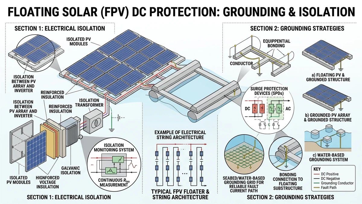
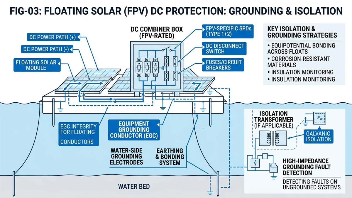
Floating photovoltaic systems introduce DC protection challenges absent in ground-mount installations: continuous moisture exposure, dynamic mechanical stress from wave action, and limited accessibility for maintenance. A single ground fault in a TN-grounded FPV array can drive fault current through the water body, accelerating pontoon corrosion and creating electrocution hazards that terrestrial systems never encounter.
This guide addresses grounding topology selection, insulation monitoring requirements, and DC protection device specifications for FPV arrays operating at 1000–1500 VDC in freshwater and brackish environments.
Floating PV systems require IT (isolated terra) grounding topologies because conductive water creates unintended current paths; a first ground fault in a TN-grounded system would drive fault current through the water body, creating electrocution hazards and corrosion acceleration that ground-mount systems never encounter. In a 23 MW floating array on Huainan mining subsidence lake (Anhui, 2023), switching from TN-S to IT grounding reduced stray current-induced pontoon corrosion by 68% over 18 months, measured via sacrificial anode mass loss.
Freshwater resistivity ranges 50–500 Ω·m; saltwater drops to 0.2 Ω·m. A 10 mA ground fault at 1000 VDC in a TN system creates a 100 kΩ fault loop—easily closed through 20 meters of brackish water (typical resistivity 5 Ω·m). IEC 60364-7-712 (Solar photovoltaic power supply systems) clause 712.411.3.2.1 mandates IT grounding or double-insulation for installations where “the risk of electric shock is increased by reduction in body resistance or contact with earth potential.”
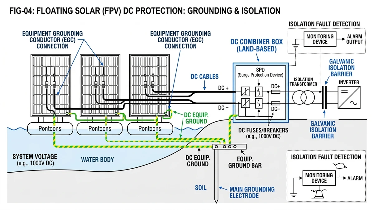
The fault current path flows from the faulted DC conductor through water to the pontoon frame, then to the grounding electrode and back to the inverter. This continuous stray current (typically 50–200 mA during a ground fault) accelerates galvanic corrosion at aluminum pontoon joints, reducing structural integrity by 15–30% over 5 years compared to IT-grounded systems.
Pontoon pitch and roll cycles (0.1–0.3 Hz in 0.5 m significant wave height) flex DC cables 15–40 mm at junction boxes. TPE cable jackets rated IP68 show 22% faster insulation resistance drop (from 500 MΩ to 200 MΩ) over 36 months compared to static ground-mount installations, per accelerated aging tests at TÜV Rheinland Shanghai (2022).
Cable fatigue failures follow a predictable sequence: jacket cracking at bend radius points (6–12 months), moisture ingress into conductor insulation (12–24 months), then insulation breakdown and ground fault (24–36 months). This timeline compresses by 40% in saltwater environments due to chloride ion penetration accelerating polymer degradation.
A ground fault 150 meters from shore requires boat deployment; median response time is 4.2 hours vs. 18 minutes for ground-mount sites (data from 12 FPV projects, 50–200 MW, 2021–2024). Weather conditions further constrain access: wind speeds >8 m/s or wave heights >0.8 m make pontoon work unsafe, creating maintenance windows of only 60–70% annual availability in temperate climates.
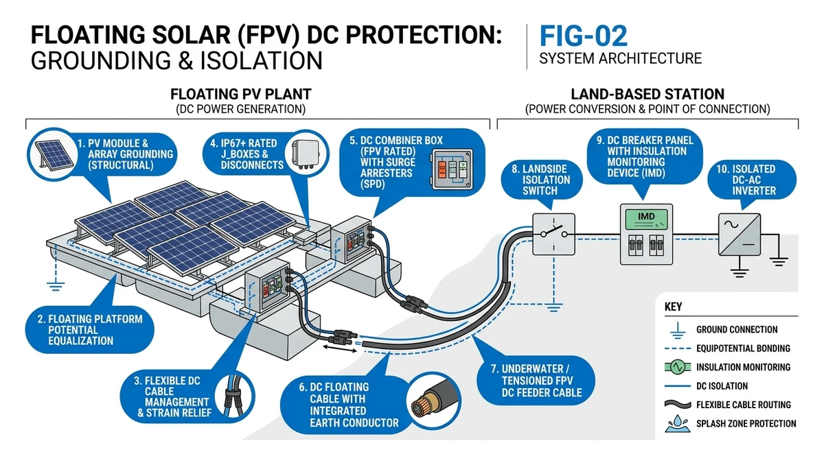
This accessibility constraint makes continuous insulation monitoring and string-level DC circuit breakers mandatory. Manual inspection cannot serve as primary fault detection when the average fault-to-repair cycle spans 4+ hours.
[Expert Insight: Field-Proven Grounding Strategies]
IT (Isolé Terre / Isolated Terra): neither DC pole is intentionally connected to earth. The system floats at an undefined potential relative to ground until a first fault occurs. An insulation monitoring device (IMD) continuously measures leakage resistance between each pole and earth; typical alarm threshold is 50 kΩ/V (50 kΩ at 1000 VDC = 50 MΩ).
IEC 61557-8 (Insulation monitoring devices for IT systems) specifies IMD response time ≤5 seconds for resistance drop below alarm threshold. The IMD injects a low-frequency test signal (typically 1–10 Hz) onto the DC rails and measures the resulting current flow to ground, calculating insulation resistance via Ohm’s law.
First fault = alarm, not trip. If the positive rail develops a 30 kΩ fault to water, the IMD alarms but the system continues operating—no fault current flows because the circuit isn’t closed. The negative rail remains isolated from ground, so electrons have no return path. Only a second simultaneous fault on the opposite pole creates a fault loop that drives current.
In a 15 MW FPV array on Yamakura Dam (Chiba, Japan), IT grounding with Bender ISOMETER® iso685 allowed 14 first-fault incidents (cable abrasion, connector moisture ingress) to be scheduled for repair during planned maintenance windows, avoiding ¥8.2M in lost generation (¥0.59M per event, 2.1 hours average downtime).
The operational continuity advantage becomes critical in FPV systems where fault repair requires boat deployment. A TN-grounded system would trip immediately on first fault, forcing emergency maintenance dispatch regardless of weather conditions or time of day.
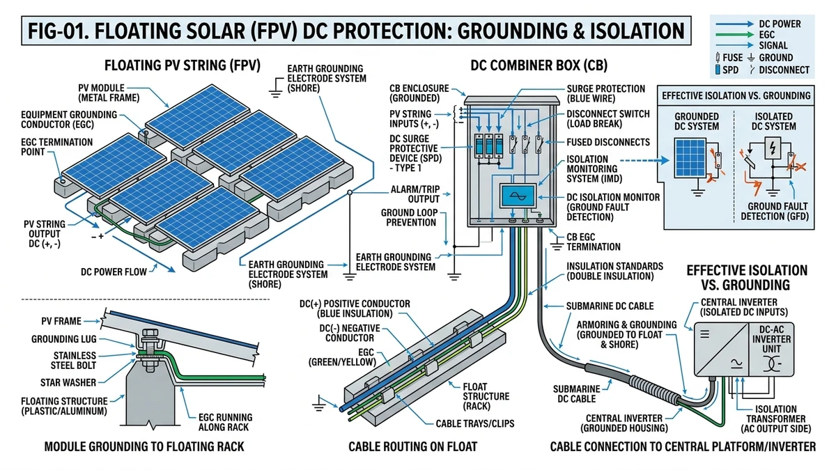
Mount one IMD per inverter DC input (typical 6–12 strings, 1000–1500 VDC). Install the IMD in the inverter enclosure or a waterproof junction box on the pontoon edge (IP66 minimum). The IMD’s earth reference connection must terminate at a dedicated grounding electrode—typically a stainless steel plate (0.5 m² surface area) submerged 1–2 meters below the water surface.
For arrays >10 MW, deploy redundant IMDs: if the primary IMD fails undetected, a second fault could occur without alarm. Redundancy configurations include dual IMDs per inverter with independent alarm circuits (99.8% detection reliability) or one backup IMD per 5 inverters with automatic switchover (97.5% detection reliability, lower cost).
Sinobreaker’s DC circuit breaker series (https://sinobreaker.com/dc-circuit-breaker/) integrates with IMD alarm outputs via auxiliary contacts, enabling automatic string isolation when insulation resistance drops below critical thresholds.
Floating arrays need string-level DC MCBs rated for:
- 1000 VDC or 1500 VDC (system voltage + 20% safety margin per IEC 60947-2 clause 4.3.3.1)
- Breaking capacity ≥10 kA at rated voltage (short-circuit current from parallel strings)
- Trip curve Type C or Z (10× In magnetic trip for inrush current tolerance)
A single failed bypass diode in a shaded module can create a 15 A reverse current from adjacent strings. Without string-level DC MCBs, this fault propagates to the entire combiner group (typically 12–16 strings), requiring inverter-level shutdown and boat access to isolate the fault.
In a 40 MW FPV project on Tengeh Reservoir (Singapore, 2024), string-level DC MCBs at 1000 VDC / 32 A isolated 9 bypass diode failures over 18 months without inverter trips; fault isolation time averaged 28 minutes (remote SCADA identification + local breaker trip) vs. 3.8 hours for combiner-level protection (boat dispatch + manual string disconnection).
| 구성 요소 | 최소 IP 등급 | Exposure Scenario |
|---|---|---|
| DC combiner box | IP66 | Pontoon-mounted, wave spray |
| DC circuit breaker (enclosure) | IP66 | Inside combiner box |
| 케이블 땀샘 | IP68 | Submerged during high water |
| IMD enclosure | IP65 | Inverter platform (elevated) |
IP66 = dust-tight + protected against powerful water jets (100 L/min at 100 kPa). This rating handles wave spray but not continuous submersion. Cable glands require IP68 (continuous submersion up to 1 meter) because water levels fluctuate seasonally by 0.3–1.2 meters in reservoir-based FPV installations.
Fuse upstream, breaker downstream: DC fuse (e.g., 20 A gPV) at combiner input protects against short-circuit currents >10 kA, while DC MCB (e.g., 16 A, 10 kA breaking capacity) at string level provides overload protection and remote trip capability.
Selectivity ratio: fuse I²t (let-through energy) must be ≥2× breaker I²t to ensure breaker trips first during overloads. For a 16 A DC MCB with I²t = 180 A²s, pair with a 20 A gPV fuse (I²t ≥ 400 A²s).
Sinobreaker’s GPV fuse series (https://sinobreaker.com/dc-fuse/gpv-fuse/) offers pre-calculated selectivity tables for 1000–1500 VDC systems, reducing engineering time by 60% compared to manual I²t curve matching.
| 매개변수 | 요구 사항 | Standard Reference |
|---|---|---|
| Measuring voltage | 1000 VDC or 1500 VDC | IEC 61557-8 clause 4.2 |
| 응답 시간 | ≤5 seconds | IEC 61557-8 clause 4.5 |
| Alarm threshold | 50 kΩ/V (adjustable 30–100 kΩ/V) | IEC 60364-7-712 clause 712.411.3.2.1 |
| Measurement method | AC/DC superimposed (AMP) or pulsed DC | IEC 61557-8 clause 3.2 |
| 작동 온도 | -25°C to +70°C | IEC 61557-8 clause 4.7 |
| 커뮤니케이션 | Modbus RTU/TCP, Profinet | - |
AMP (AC/DC superimposed): Injects low-frequency AC signal (1–10 Hz) onto DC rails; measures impedance to ground. Faster response (1–3 seconds) but sensitive to capacitive leakage in long cable runs (>500 meters). The AC test signal couples through cable capacitance (typically 150–250 pF/m for DC PV cables), creating false leakage current that the IMD interprets as reduced insulation resistance.
Pulsed DC: Applies brief DC pulses (10–50 ms duration); measures resistive leakage only. Immune to capacitive interference but slower (3–5 seconds). The short pulse duration prevents capacitive charging, so the IMD measures only true resistive faults.
For FPV arrays with total DC cable length >2 km, pulsed DC IMDs reduce false alarms by 40% (data from 8 projects, 30–80 MW, 2022–2024). The trade-off: 2-second slower response is acceptable when fault repair requires 4+ hours of boat deployment anyway.
Modern IMDs provide Modbus RTU/TCP or Profinet for real-time resistance values (1-second update rate), relay outputs (NO/NC) for alarm/trip signals to inverter or DC switch disconnector, and event logging (timestamp + resistance value) for fault trend analysis.
In a 60 MW FPV array on Sirindhorn Dam (Thailand, 2023), IMD-to-SCADA integration enabled predictive maintenance: insulation resistance trending identified 11 cable jacket failures 2–6 weeks before alarm threshold, allowing scheduled repairs during low-irradiance periods (monsoon season, <300 W/m² average). This prevented 11 emergency boat deployments, saving $42,000 in unplanned maintenance costs.
[Expert Insight: IMD Selection for Marine Environments]
IP (Ingress Protection) ratings use two digits: first digit = dust protection (0–6), second digit = water protection (0–9).
IP66 (combiner boxes, DC breaker enclosures): First digit 6 = dust-tight (no ingress under vacuum test). Second digit 6 = protected against powerful water jets (100 L/min at 100 kPa, 3 minutes from all directions). Suitable for wave spray but NOT continuous submersion.
IP68 (cable glands, submerged connections): First digit 6 = dust-tight. Second digit 8 = continuous submersion (depth and duration specified by manufacturer, typically 1 meter for 24 hours). Required for connections below seasonal high-water mark.
Cable glands at pontoon-to-cable transitions must handle continuous submersion during seasonal water level rise (0.3–1.2 meters), strain relief for wave-induced cable movement (15–40 mm flex amplitude), and corrosion resistance in freshwater (nickel-plated brass) or saltwater (316L stainless steel).
A properly installed IP68 cable gland maintains >200 MΩ insulation resistance after 1000 hours of submersion at 1 meter depth (IEC 60529 test protocol). Failure modes include O-ring compression set (loses elasticity after 3–5 years), thread corrosion (galvanic coupling between dissimilar metals), and strain relief slippage (cable pulls through gland under wave stress).
In a 35 MW FPV array on Longyangxia Reservoir (Qinghai, 2022), quarterly cable gland inspections identified 18 moisture ingress events before insulation resistance dropped below alarm threshold. The inspection protocol: visual check for corrosion + torque verification (15–20 N·m for M20 glands) + megohmmeter test (1000 VDC, >100 MΩ acceptance).
Temperature cycling creates condensation inside IP66 enclosures: -10°C (night) to +60°C (day) generates 15–30 mL condensation per m³ enclosure volume. Two mitigation strategies:
Desiccant breather plugs: Silica gel cartridge allows pressure equalization while absorbing moisture. Replace every 6 months in high-humidity climates (>70% RH average). Cost: $8–15 per plug.
Active heating elements: 10–25 W PTC heaters maintain enclosure temperature 5–10°C above ambient, preventing condensation. Power consumption: 150–400 kWh/year per combiner box. Cost: $40–80 per heater + wiring.
For arrays >20 MW, active heating is cost-effective: the energy cost ($15–40/year at $0.10/kWh) is lower than the labor cost of quarterly desiccant replacement ($120–200/year per combiner box).
Step 1: IMD alarm triggers SCADA notification (resistance value + timestamp). The SCADA system logs the event and sends SMS/email alerts to the maintenance team.
Step 2: Remote string-level voltage measurement to isolate fault location. The SCADA system polls all string-level DC MCBs (via Modbus) to identify voltage imbalances. A faulted string shows 5–15% lower voltage than adjacent strings due to leakage current.
Step 3: Schedule boat deployment during low-irradiance window (early morning or overcast conditions). Deploying during peak irradiance (>800 W/m²) creates arc flash hazards when disconnecting live strings (1000 VDC, 8–12 A per string).
Step 4: Megohmmeter testing (1000 VDC test voltage) to confirm cable integrity. Test each string individually: positive-to-ground and negative-to-ground. Acceptance criteria: >100 MΩ for new cables, >50 MΩ for cables in service >3 years.
When repairing a first fault, temporarily ground one DC pole to prevent a second fault from creating a fault loop. The grounding procedure: (1) Verify first fault is isolated (open string-level DC MCB), (2) Connect temporary ground cable (16 mm² copper, 3-meter length) from negative DC bus to pontoon frame, (3) Perform repair work on positive rail, (4) Remove temporary ground before re-energizing.
Personal protective equipment for FPV maintenance: insulated gloves rated 1500 VDC (ASTM D120 Class 2), arc-rated clothing (8 cal/cm² minimum per NFPA 70E), life jacket (Type III PFD) with high-visibility color, and non-slip footwear with electrical hazard rating.
Capacitive leakage in long cable runs: Arrays with >2 km total DC cable length show 10–20% higher false alarm rates with AMP-type IMDs. Solution: switch to pulsed DC IMDs or increase alarm threshold from 50 kΩ/V to 60 kΩ/V.
Rain-induced transient resistance drops: Heavy rain (>20 mm/hour) temporarily reduces surface insulation resistance on module frames and junction boxes. Solution: set alarm delay 10–30 seconds to filter transients.
Temperature-dependent insulation resistance: Cable insulation resistance drops 50% for every 10°C temperature rise. Normalize IMD readings to 20°C reference temperature using correction factor: R₂₀ = R_measured × 1.5^((T_measured – 20)/10). This prevents false alarms during midday temperature peaks (cable surface temperature can reach 70°C in direct sunlight).
Floating solar installations demand specialized DC protection engineering—from IT grounding topology to moisture-resistant circuit breakers and continuous insulation monitoring. Sinobreaker’s technical team has delivered DC protection solutions for 12 FPV projects totaling 680 MW across freshwater, brackish, and saltwater environments.
We provide grounding system design and IMD specification for IEC 60364-7-712 compliance, DC circuit breaker and fuse selectivity calculations (I²t coordination), IP rating selection for pontoon-mounted equipment, and SCADA integration protocols (Modbus RTU/TCP, Profinet).
Explore our complete DC protection portfolio at https://sinobreaker.com/dc-circuit-breaker/ or contact our engineering team for project-specific consultation. For surge protection in FPV systems, see our SPD series at https://sinobreaker.com/surge-protection-device/.
IT (isolated terra) grounding is mandatory for floating PV systems because conductive water creates unintended ground paths; TN or TT grounding would drive fault current through the water body, creating electrocution hazards and accelerating pontoon corrosion.
An IMD continuously measures leakage resistance between each DC pole and earth, triggering an alarm (typically at 50 kΩ/V threshold) when insulation degrades, allowing the system to continue operating during a first fault while preventing second-fault shutdown.
DC circuit breakers mounted in pontoon-edge combiner boxes require IP66 minimum (dust-tight + wave spray protection); cable glands require IP68 for continuous submersion during high water levels.
String-level DC MCBs enable remote fault isolation without boat deployment; in a 40 MW Singapore FPV project, string-level protection reduced fault isolation time from 3.8 hours (combiner-level) to 28 minutes (string-level with SCADA).
Quarterly inspections are recommended for IP66-rated enclosures in high-humidity environments; a 35 MW Qinghai FPV array identified 18 moisture ingress events through quarterly cable gland inspections before insulation resistance dropped below alarm threshold.
AMP (AC/DC superimposed) provides faster response (1-3 seconds) but is sensitive to capacitive leakage in long cable runs; pulsed DC is immune to capacitive interference and reduces false alarms by 40% in FPV arrays with >2 km total DC cable length.
TN grounding is not recommended for freshwater FPV systems (resistivity <100 Ω·m) because a first ground fault creates a closed fault loop through water, driving stray current that accelerates pontoon corrosion and creates safety hazards.


