Address
304 North Cardinal
St. Dorchester Center, MA 02124
Work Hours
Monday to Friday: 7AM - 7PM
Weekend: 10AM - 5PM
Address
304 North Cardinal
St. Dorchester Center, MA 02124
Work Hours
Monday to Friday: 7AM - 7PM
Weekend: 10AM - 5PM

As PV and ESS architectures move to higher DC bus voltages, surge protection has to scale with the electrical stress, not just the nameplate number.
A 1500V DC surge protective device (SPD) is a transient overvoltage suppressor rated for photovoltaic and energy storage systems operating at up to 1500 VDC. It clamps lightning-induced and switching surges before they reach inverters, string combiners, or battery management systems, protecting assets where replacement costs routinely exceed $50,000 per inverter unit.
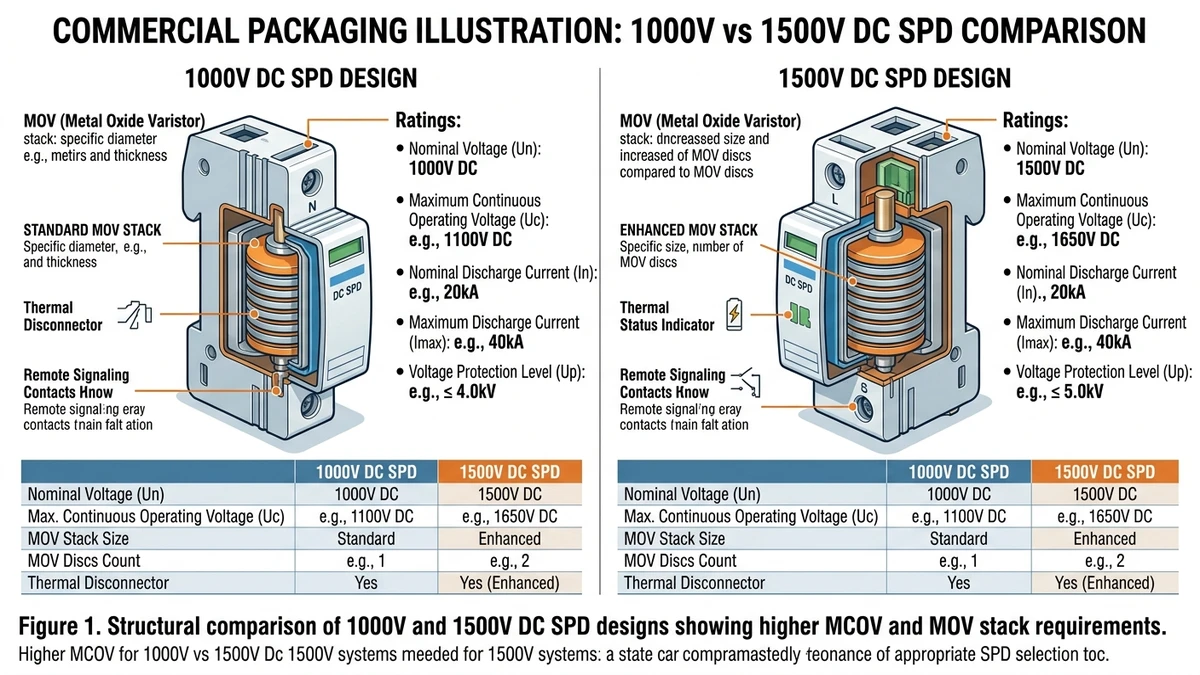
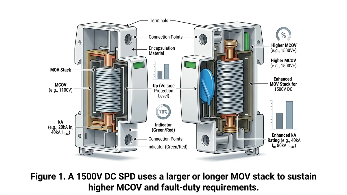
The 500V difference is not a simple scaling factor. It represents a different operating regime for the metal oxide varistor (MOV) stack at the core of every DC SPD.
In a 1000V design, the MOV column typically uses a series stack sized to maintain a maximum continuous operating voltage (MCOV) of around 850–900 VDC. At 1500V system voltage, the MCOV requirement rises to approximately 1200–1300 VDC. This forces engineers to either increase the number of MOV discs in series or use larger-diameter varistor elements with higher energy absorption capacity, typically 2.5–4 kJ versus 1.0–1.8 kJ in 1000V counterparts.
A 1000V-rated SPD installed in a 1500V string circuit will operate continuously above its MCOV threshold, accelerating thermal runaway. IEC 61643-11 requires DC SPDs to demonstrate stable clamping voltage (Up) and thermal stability under continuous DC stress, and the test conditions for 1500V-class devices are stricter than those for 1000V units.
A 1500V DC SPD must also handle a higher prospective short-circuit current (Isc) at the point of installation. In utility-scale PV plants with 1500V string architecture, Isc at the combiner bus commonly reaches 20–40 kA, requiring SPDs with a matching short-circuit withstand rating — a parameter that does not simply transfer from 1000V-rated devices.
In a 120 MW ground-mount installation in Qinghai Province (2023), field engineers replacing 1000V SPDs with properly rated 1500V devices observed that the previous units showed MOV degradation within 14 months of commissioning, consistent with chronic MCOV overstress rather than surge events.
Detailed multi-stage coordination is covered in the DC surge protection system design guide. Designers can also review the surge protection device series to confirm voltage class alignment before specifying any SPD for a 1500V architecture.
Once voltage class is correct, the next decision is installation type, because the wrong SPD class at the wrong location either wastes budget or leaves the highest-risk point exposed.
IEC 61643-31 governs surge protective devices for DC power systems, including photovoltaic installations operating at 1500V DC. It defines Type 1, Type 2, and combined Type 1+2 SPDs based on test waveform, impulse current rating, and installation position.
Type 1 devices handle direct lightning current injection and are tested with the 10/350 μs waveform. They belong at the service entrance, main DC bus, or any location bonded to the lightning protection system (LPS). Type 2 devices address switching transients and attenuated lightning surges deeper in the system and are tested with the 8/20 μs waveform. Type 1+2 units combine both capabilities and are increasingly common in 1500V DC plants where panel space and installation cost matter.
In a 120 MW ground-mount installation in Inner Mongolia (2023), the engineering team specified Type 1+2 SPDs at each 1500V DC combiner box output, reducing total SPD count by 38% compared with a two-stage approach without compromising protection levels at the inverter DC input terminals.
| Parameter | Type 1 | Type 2 | Type 1+2 |
|---|---|---|---|
| Test waveform | 10/350 μs | 8/20 μs | Both |
| Impulse current (Iimp / Imax) | Iimp ≥ 12.5 kA | Imax up to 40 kA | Both ratings apply |
| Uc (max continuous voltage) | ≥ 1500V DC | ≥ 1500V DC | ≥ 1500V DC |
| Typical installation point | Main DC busbar, LPS bonding point | String combiner output, inverter DC input | Combiner box, compact 1500V DC arrays |
| 1500V DC applicability | Required where direct strike exposure exists | Standard for most string-level protection | Preferred for space-constrained 1500V plants |
| Coordination with upstream OCP | Requires dedicated backup fuse (e.g., gPV fuse) | Typically self-protected or fused internally | Verify manufacturer’s backup protection requirement |
Type 1 belongs at the first point of entry connected to the LPS equipotential bonding network. If the plant has an external air-termination system, Type 1 is mandatory at that interface. Guidance on lightning risk and placement is available from the IEC overview on surge protective devices.
Type 2 sits at the PV combiner box output and at inverter DC input terminals, where switching-induced transients and attenuated lightning surges dominate.
Type 1+2 is often the practical choice where the combiner box is the only accessible installation point between the string field and the inverter. A single Type 1+2 unit rated at Uc ≥ 1500V DC and Imax ≥ 20 kA covers both threat categories without requiring a two-device cascade.
[Expert Insight]
– If the array frame is integrated into an external lightning protection system, assume higher surge exposure and evaluate Type 1 or Type 1+2 at the first DC aggregation point.
– On retrofit projects, verify the installed SPD test class from the label, not from old drawings; many legacy schedules list “SPD” without Type 1/2 distinction.
– Where combiner space is tight, confirm thermal spacing and fuse clearance before choosing a combined Type 1+2 unit.
Field performance comes down to a few electrical numbers, and most premature failures can be traced to one of them being ignored or misread.
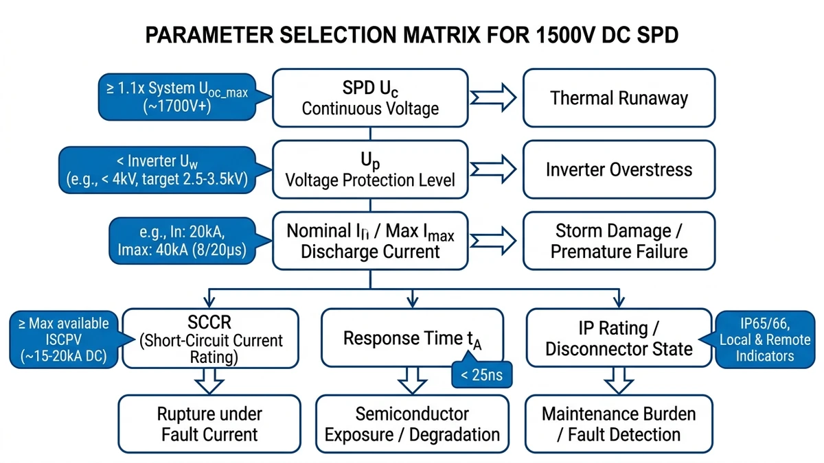
Selecting a 1500V DC SPD comes down to six electrical parameters. Get any one wrong and the device either clamps too late to protect the inverter or conducts continuously and fails early.
Uc is the most critical parameter and the one most commonly undersized. For a 1500V DC string system, the open-circuit voltage (Voc) at minimum temperature must be the baseline, not nominal string voltage.
The standard calculation method per IEC 61643-11 (SPDs for low-voltage power systems):
Undersizing Uc causes the varistor to conduct at normal operating voltage, generating heat that accelerates degradation.
Up defines the clamping voltage the SPD presents to connected equipment during a surge. For inverter protection, Up must be coordinated against the inverter’s rated impulse withstand voltage (Uimp). A common design rule is Up below 80% of equipment Uimp. Most 1500V string inverters carry a Uimp of 6 kV, so Up should not exceed 4.8 kV. Devices advertising Up of 2.5–4 kV at In = 20 kA are the practical target range for utility-scale deployments.
In sets the repetitive surge rating; Imax is the single-event maximum. For installations in high-keraunic zones, with ground flash density above 4 flashes/km²/year, specify Imax ≥ 40 kA. A 120 MW ground-mount project in Yunnan Province (2023) recorded direct strike events exceeding 30 kA peak current; SPDs rated at Imax = 40 kA survived while 20 kA-rated units required replacement after the first storm season.
The SPD must withstand the prospective fault current at its installation point without rupturing. At 1500V DC busbars, SCCR requirements commonly reach 25–50 kA. Pair SPD selection with appropriately rated DC fuses or DC circuit breakers for backup overcurrent protection.
DC SPDs using MOV technology respond in under 25 ns. Spark-gap types respond in 100 ns or more. For inverter IGBT protection, MOV-based or hybrid designs are typically preferred since IGBT gate insulation can fail within microseconds of an unclipped transient.
For outdoor combiner box installations, IP65 minimum is required. Thermal disconnectors with remote fault signaling reduce inspection labor significantly; in a typical 50 MW plant with 80+ combiner boxes, manual SPD status checks without remote indication add roughly 4–6 person-hours per quarterly inspection cycle.
Even a correctly rated SPD can underperform if its wiring mode does not match the DC grounding scheme actually used in the plant.
Grounding topology is the most consequential variable in 1500V DC SPD wiring design. The wrong configuration can reduce protection effectiveness, create ground-fault current paths that trip GFDI relays, damage inverters, or leave the system unprotected during a surge event.
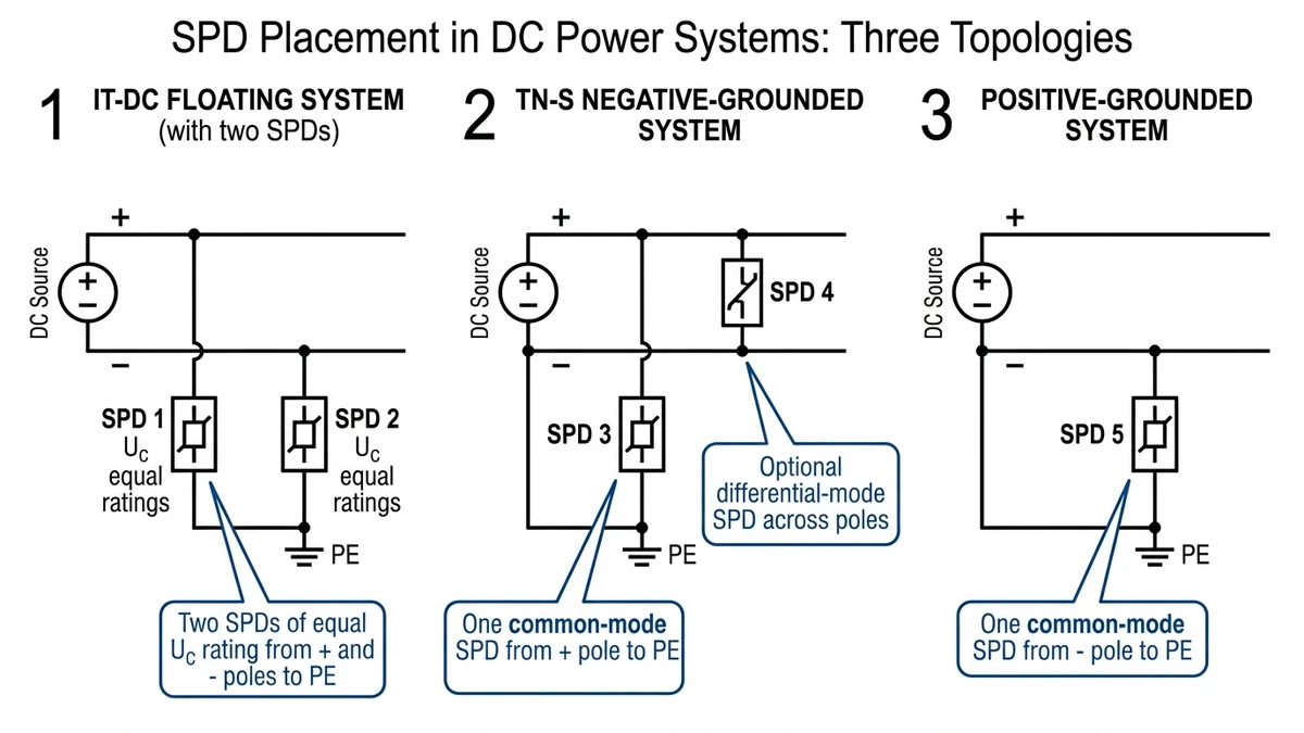
In floating IT-DC systems, neither pole is intentionally connected to earth. This is common in battery storage and some off-grid PV configurations. SPDs must be installed from both the positive pole to PE and the negative pole to PE using a two-SPD configuration with matched Up values, typically no more than 2.5 kV for 1500V bus systems. A single-pole SPD creates asymmetric clamping and leaves one conductor unprotected.
Each SPD in an IT-DC floating system must be rated for the full line-to-earth voltage. For a 1500 VDC bus, this means a Uc (maximum continuous operating voltage) of ≥ 1000 V per SPD module, since the full bus voltage can appear across either pole-to-earth path under a single ground fault condition.
Most utility-scale 1500V PV plants use negative-grounded TN-S topology, where the negative pole is bonded to PE. Here, only the positive pole requires an SPD to PE, but that SPD must handle the full line-to-earth differential. A second SPD across the positive-to-negative conductors is often added for differential-mode surge suppression. In a 120 MW ground-mount project in Inner Mongolia (2023), this dual-mode configuration reduced inverter input surge damage incidents by an estimated 70% compared with a single-ended installation.
Positive-grounded DC systems appear in some legacy thin-film PV installations to mitigate potential-induced degradation. The SPD connects from the negative pole to PE. The Uc requirement is identical to the negative-grounded case, but polarity-sensitive MOV assemblies must be verified for correct orientation because reversed installation is a documented field failure mode.
[Expert Insight]
– Before ordering SPDs, confirm the as-built grounding topology at the inverter skid and combiner box; EPC drawings and field terminations do not always match.
– Keep SPD leads short and symmetrical in floating systems to avoid unequal inductive voltage drop between positive-to-PE and negative-to-PE paths.
– When adding a differential-mode SPD in negative-grounded systems, check enclosure layout so the PE bond remains the shortest path.
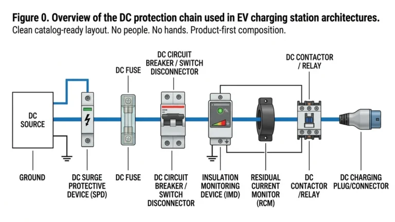
Surge protection only works reliably when the SPD, fuse, and breaker are treated as one coordinated protection chain rather than separate catalog items.
Effective 1500V DC SPD coordination means each protective device handles the duty it is rated for: the SPD absorbs transient energy, the fuse limits prospective fault current, and the DC circuit breaker provides isolation.
A common sequence from the PV array toward the inverter is: lightning protection zone boundary → Type 1 SPD → Type 2 SPD → gPV string fuse → DC circuit breaker → inverter DC input. Each stage clamps progressively lower voltage while the fuse and breaker handle any follow current the SPD cannot self-extinguish.
In a 120 MW ground-mount installation in Inner Mongolia (2023), engineers found that omitting the Type 1 stage caused Type 2 SPDs to absorb full 10/350 μs lightning impulse currents they were not rated for, resulting in thermal runaway failures within the first monsoon season. Adding correctly rated Type 1 devices upstream resolved the issue.
The coordination principle is that the let-through I²t of the upstream fuse must be less than the withstand I²t of the protected downstream device. For 1500V DC string circuits, gPV fuses rated to IEC 60269-6 typically carry pre-arcing I²t values in the range of 500–5000 A²s depending on current rating, which must remain below the SPD’s internal component withstand threshold.
The coordination check follows: I²tfuse (pre-arc) < I²tSPD withstand. If the SPD’s varistor or spark gap has a withstand I²t of, say, 3000 A²s, the selected fuse must clear within that energy budget — typically achievable with a 10 A gPV fuse at 1500 VDC.
For the DC circuit breaker downstream, IEC 60947-2 governs short-circuit breaking capacity (Icu). The breaker’s rated Icu at 1500 VDC must exceed the prospective short-circuit current at that point in the string circuit, commonly 2–4 kA in utility-scale architectures.
Environmental stress changes the effective capability of the SPD, so a valid sea-level selection can become underspecified once the plant goes uphill or runs hot.
Most 1500V DC SPD failures in high-altitude and high-temperature deployments trace back to applying sea-level, 40°C nameplate ratings without derating. When ambient conditions exceed those baselines, the SPD’s actual protection level can rise and its Uc margin can shrink enough to cause continuous overstress.
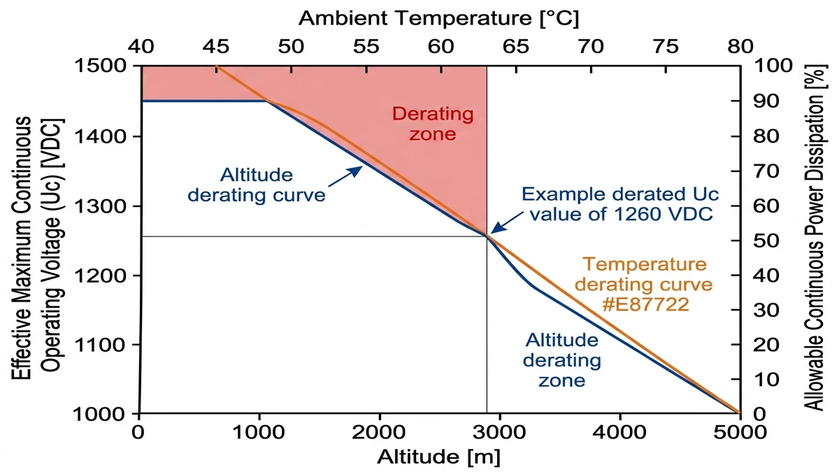
Air density drops roughly 11% per 1000 m of elevation. Above 2000 m, reduced dielectric strength lowers the ionization threshold for internal air gaps. IEC 61643-11 requires manufacturers to specify derating factors for altitudes above 2000 m, but some datasheets bury this in notes or omit it.
A practical derating rule for altitude: for every 1000 m above 2000 m, apply a voltage derating factor of approximately 8–10% to the rated Uc. At 4000 m, that means a device rated 1500 VDC at sea level should be derated to roughly 1200–1380 VDC effective Uc — a gap that matters when your string voltage sits at 1450 VDC under cold-morning open-circuit conditions.
MOV-based SPDs are thermally sensitive. Leakage current through the varistor increases with temperature, accelerating aging and reducing clamping stability. Above 60°C ambient, common inside poorly ventilated combiner boxes in desert climates, continuous power dissipation may need to be derated by 15–25% depending on MOV formulation.
In a 120 MW ground-mount installation in Qinghai Province (2023), operating at 3200 m elevation with summer enclosure temperatures reaching 68°C, field teams recorded SPD failure rates roughly three times higher than the project’s coastal reference sites. Post-failure analysis pointed to combined altitude and thermal stress rather than lightning events.
With the electrical ratings, topology, and derating rules established, commissioning success usually depends on a short list of installation checks done before energization.
Multi-stage coordination across string, combiner, and inverter levels is explained in the DC surge protection system design guide. Browse Sinobreaker’s surge protection device range for 1500V DC-rated options with remote fault signaling.
A 1500V unit is built to survive higher continuous DC stress, with higher Uc and usually a larger or longer MOV stack. A 1000V SPD used on a 1500V system can overheat even without a major surge.
It should be placed at the first DC point exposed to lightning current, typically where the DC system interfaces with the lightning protection or main distribution point. That location sees the highest impulse energy.
Base it on the maximum possible open-circuit string voltage at the coldest expected site condition, not on nominal operating voltage. If temperature correction pushes Voc upward, the SPD must still remain below continuous conduction.
No. Floating, negative-grounded, and positive-grounded DC systems require different wiring modes, and using the wrong one can leave one conductor exposed or create nuisance ground-fault behavior.
Long leads add inductance, and that inductance creates extra voltage during a fast surge. Even a well-rated SPD can let more voltage reach the inverter if the conductors are routed too long or unevenly.
In many installations, yes. The SPD handles transient energy, but a correctly coordinated fuse or breaker is needed to clear fault current if the SPD fails short or cannot interrupt follow current safely.
Yes. High elevation and hot enclosure conditions can reduce effective voltage margin and increase thermal stress, so derating has to be included before finalizing the SPD rating.