Address
304 North Cardinal
St. Dorchester Center, MA 02124
Work Hours
Monday to Friday: 7AM - 7PM
Weekend: 10AM - 5PM
Address
304 North Cardinal
St. Dorchester Center, MA 02124
Work Hours
Monday to Friday: 7AM - 7PM
Weekend: 10AM - 5PM


Surge Protector for Solar Panels sizing and coordination determines whether your solar panel installation survives lightning strikes and transient events that threaten expensive equipment. Proper surge protection requires more than simply installing generic devices—you must calculate appropriate ratings, coordinate multiple protection stages, and integrate surge protectors with overcurrent protection and grounding systems. This comprehensive guide covers everything solar designers and installers need for effective surge protection.
Lightning represents the primary threat to solar installations, with a single strike delivering enough energy to instantly destroy inverters, modules, and monitoring systems worth tens of thousands of dollars. Even near-miss strikes hundreds of meters away induce damaging voltages through electromagnetic coupling with array conductors. Proper surge protector selection prevents these losses through systematic sizing and coordination.
Solar photovoltaic systems present unique surge protection challenges compared to standard electrical installations. Arrays mount in exposed locations—often the highest points on buildings—making them lightning attraction targets. Long DC conductor runs between arrays and inverters act as collection antennas for electromagnetic energy from lightning strikes, converting transient fields into damaging voltages and currents.
DC surge protection differs fundamentally from AC applications. Direct current maintains constant voltage without zero-crossings, creating sustained arcing in protective devices that AC systems avoid through natural current zeros occurring 120 times per second. Surge protectors for solar must handle this DC arc extinction challenge while operating at voltages commonly reaching 600V to 1500V—substantially higher than residential AC voltages.
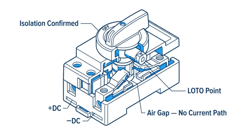
Solar arrays remain energized whenever light hits modules, making complete de-energization impossible without physically covering arrays or waiting for darkness. This permanent energization means surge protectors must accommodate both line-side and load-side voltage simultaneously—opening disconnects doesn’t eliminate shock or surge hazards from the array side of equipment.
💡 Key Insight: Solar surge protection isn’t optional luxury equipment—NEC 690.35 mandates surge protection devices when DC circuit conductors exceed 2 meters from the array, covering virtually all installations except micro-inverter systems with module-level electronics.
NEC Article 690.35 establishes surge protection device requirements for photovoltaic systems including specific provisions affecting sizing and coordination. Section 690.35(A) mandates SPDs for DC circuits when conductors are located more than 2 meters (6.6 feet) from the PV array, effectively requiring surge protection on nearly all solar installations except those with micro-inverters mounted directly at modules.
The code requires SPDs rated for the maximum available voltage and current at their installation point. Section 690.35(D) specifies that SPDs must have voltage ratings appropriate for the circuit voltage and current ratings sufficient for available fault current. While the code doesn’t specify exact rating values, it places responsibility on designers to properly calculate and specify adequate ratings.
Installation location requirements under 690.35 mandate SPDs at the first readily accessible location on DC circuits. For most systems this means array combiners, main DC disconnects at building entrances, or inverter DC input terminals. The code’s flexibility allows designers to optimize protection placement based on system configuration while ensuring surge protection exists where most effective.
Surge protector current ratings must account for the maximum surge current expected at the installation location based on lightning exposure and system configuration. The nominal discharge current (In) rating indicates surge current the device handles repeatedly without degradation—typically tested with 15-20 surge applications. Maximum discharge current (Imax) represents the highest single surge the device survives without catastrophic failure.
Lightning exposure assessment determines appropriate current ratings. The keraunic level—average annual thunderstorm days—indicates relative lightning risk. Regions with 40+ thunderstorm days annually face high exposure requiring robust surge protection. Ground flash density data, when available, provides more precise lightning risk assessment measured in flashes per square kilometer per year.
| Lightning Exposure | Keraunic Level | Type 1 SPD Rating | Type 2 SPD Rating |
|---|---|---|---|
| Low | <20 days/year | 25kA (10/350μs) | 15kA (8/20μs) |
| Moderate | 20-40 days/year | 40kA (10/350μs) | 20kA (8/20μs) |
| High | 40-60 days/year | 50-60kA (10/350μs) | 25kA (8/20μs) |
| Extreme | >60 days/year | 80-100kA (10/350μs) | 30-40kA (8/20μs) |
Installation location affects required current rating. Array combiners and main DC disconnects near exposed arrays face highest surge energy requiring Type 1 surge protectors with 10/350μs current ratings. Equipment locations like inverter DC inputs face attenuated surges after conductor impedance reduces energy, allowing Type 2 devices with lower 8/20μs ratings. The different waveforms represent dramatically different energy content—10/350μs waveforms deliver roughly 20 times more energy than 8/20μs at the same peak current.
Type 1 surge protectors undergo testing with 10/350μs current waveforms simulating direct lightning strike current characteristics. The long 350-microsecond tail of this waveform delivers sustained high energy requiring robust surge protector construction. Type 1 devices rated 40kA (10/350μs) handle approximately 10 megajoules of energy per pulse—enough to vaporize inadequately rated protection devices.
Type 2 surge protectors test with 8/20μs waveforms representing induced lightning currents and switching transients. The shorter 20-microsecond tail contains far less energy than Type 1 waveforms. A 20kA Type 2 device (8/20μs) handles roughly 250 kilojoules—only 2.5% of the energy a 40kA Type 1 device manages. This dramatic difference explains why Type 1 devices cost substantially more and why proper SPD type selection for each location proves critical.
Don’t confuse the current ratings—a 20kA Type 2 device is NOT equivalent to a 20kA Type 1 device despite the same peak current number. The energy handling differs by orders of magnitude. A 20kA (8/20μs) Type 2 device handles similar energy to perhaps a 2-3kA (10/350μs) Type 1 device. Always specify both the current rating AND the waveform type to ensure proper device selection.
⚠️ Important: Beware of surge protector manufacturers listing only peak current ratings without specifying waveform type. This omission often hides inferior energy handling. Demand complete specifications including “In (10/350μs)” for Type 1 devices and “In (8/20μs)” for Type 2 devices.

Maximum continuous operating voltage represents the highest voltage a surge protector withstands continuously without degradation or false activation. MCOV must exceed the maximum voltage appearing across the surge protector under all normal operating conditions including temperature variations, partial shading effects, and inverter maximum power point tracking behavior.
Solar array voltage varies significantly with temperature and irradiance. Cold weather increases module open-circuit voltage substantially—some modules gain 0.3-0.4% per degree Celsius below standard test conditions. A module rated 40V VOC at 25°C might reach 50V at -20°C, representing 25% increase. String voltage calculations must account for this temperature coefficient using NEC 690.7 lowest expected ambient temperature methodology.
Maximum power point voltage differs from open-circuit voltage, typically running 75-85% of VOC. Inverters normally operate arrays at MPP voltage, making this the relevant voltage for MCOV selection rather than VOC. However, surge protector specifications must account for the full voltage range from MPPT minimum to temperature-corrected VOC maximum. MCOV should exceed MPP voltage by 10-20% providing margin for voltage variations without approaching VOC where protection might be needed.
Voltage protection rating—also called clamping voltage—indicates the maximum voltage appearing across protected equipment during surge events. Lower VPR values provide better protection by limiting voltage exposure to safer levels. However, VPR must remain sufficiently above MCOV to prevent false surge protector activation during normal voltage transients from cloud-edge effects, inverter switching, or other legitimate system operations.
Equipment withstand voltage establishes the upper limit for acceptable VPR. Inverters typically withstand 2000-2500V on DC inputs, though specifications vary by manufacturer and model. The surge protector VPR plus voltage rise from lead inductance must stay below this equipment limit. If VPR equals 1500V and lead inductance adds 400V overshoot during fast transients, effective equipment exposure reaches 1900V—adequate for 2000V withstand rating but marginal for equipment with lower limits.
Coordinate VPR across multiple protection stages to ensure proper operation. When using Type 1 and Type 2 surge protectors in series, the Type 1 device should have higher VPR (typically 1800-2000V) while Type 2 devices clamp tighter (1200-1500V). This voltage differential ensures the upstream Type 1 device activates first handling high energy, then the Type 2 device provides fine clamping for equipment protection after surge energy reduces to manageable levels.
Individual string voltage determines surge protector requirements at combiner level, while combined system voltage affects main disconnect and inverter input protection. A system with ten 500V strings in parallel presents 500V to surge protectors at each string position but might combine into a 5kW system operating at the same 500V with higher current capacity. The per-string protection sees only individual string surge current, not the combined current from multiple strings.
However, main DC disconnect and inverter input surge protectors must handle the combined surge energy from all parallel strings. If each string can deliver 1000A surge current, a ten-string array potentially delivers 10,000A at the main disconnect during events affecting multiple strings simultaneously. Main disconnect surge protectors need current ratings accounting for this combined exposure, typically 2-3 times individual string surge current.
Grounded versus ungrounded system configuration affects voltage ratings differently. Ungrounded (floating) systems develop voltage symmetrically on both positive and negative conductors relative to ground—a 600V system might show +300V and -300V to ground. Surge protectors for each conductor see only their conductor-to-ground voltage, potentially allowing lower-rated devices. Grounded systems place full voltage on the ungrounded conductor requiring higher surge protector ratings on that conductor.
Primary surge protection typically installs at array combiners or string boxes where conductors originate from exposed PV arrays. This first protection stage faces maximum surge energy from direct lightning strikes or electromagnetically induced currents from nearby strikes. Type 1 surge protectors rated for 10/350μs waveforms provide appropriate robustness for primary protection duty.
Primary stage current ratings should account for worst-case direct strike scenarios. Lightning strikes to arrays or nearby structures can inject currents exceeding 100kA into electrical systems. While individual surge protectors don’t handle this full current—it distributes across multiple paths to ground—conservatively rate primary protection at 40-60kA (10/350μs) in moderate exposure locations and 80-100kA in high-exposure areas.
Install primary protection with shortest possible ground connections using conductors sized 6 AWG minimum for Type 1 devices. Every meter of ground conductor introduces roughly 1μH inductance causing approximately 1kV voltage rise per meter during typical surge current rise rates. Long ground connections defeat protection effectiveness by allowing excessive voltage rise despite surge protector operation. Aim for ground connections under 1 meter using straight runs without unnecessary bends.
🎯 Pro Tip: Mount primary surge protectors inside combiner boxes or immediately adjacent to them rather than remotely on walls. Close mounting minimizes lead lengths both to protected conductors and to grounding electrodes, significantly improving protection effectiveness with minimal cost penalty.
Secondary protection at building entrance points—typically main DC disconnects—provides backup protection and guards against surges entering from the building electrical system side. This protection stage operates after conductor impedance has attenuated surge energy from array-origin events, allowing somewhat lower current ratings than primary protection while maintaining adequate safety margins.
Type 1 surge protectors remain appropriate for building entrance locations despite reduced energy exposure, providing robustness against unexpected threats. Rate secondary protection at 30-50kA (10/350μs) depending on distance from primary protection and lightning exposure. Systems with long conductor runs between primary and secondary protection benefit from higher secondary ratings since more electromagnetic energy couples into long conductor segments.
Coordinate secondary protection voltage ratings to activate at slightly lower voltages than primary devices. If primary protection clamps at 1800V and secondary at 1600V, during coordinated operation the primary device handles initial surge energy then the secondary device provides additional clamping as current reduces. This voltage progression guides surge energy through protection stages without devices fighting each other.
Final protection stage at inverter DC inputs and other sensitive equipment provides precise voltage clamping for electronics protection. Type 2 surge protectors rated for 8/20μs waveforms suit equipment locations where upstream protection and conductor impedance have reduced surge threats to moderate levels. Equipment-level protection focuses on tight voltage clamping rather than maximum energy handling.
Rate equipment protection at 15-25kA (8/20μs) providing adequate capacity for surges reaching this location. The lower ratings compared to Type 1 devices reflect the reduced threat at protected equipment locations, not inadequate protection. Attempting to use Type 1 devices everywhere wastes money on unnecessary high-energy capability while potentially providing worse voltage clamping due to Type 1 devices’ typically higher VPR.
Install equipment-level surge protectors directly at protected device terminals—within 0.5 meters ideally. Lead inductance voltage rise proves especially critical at equipment locations where tight clamping voltage protects sensitive semiconductors. Even short conductor runs between surge protector and equipment introduce voltage rise negating protection benefits. Many modern inverters integrate surge protection eliminating external installation requirements, though verify integrated protection meets system needs before skipping external devices.

Surge protector effectiveness depends critically on proper grounding. Surge protectors divert surge current to ground, requiring low-impedance ground connections to function effectively. All surge protectors in a solar installation should connect to a single common grounding electrode system, preventing ground potential differences that cause surge current flow through equipment between ground points.
The grounding electrode system should meet or exceed NEC 250.50 requirements, typically consisting of ground rods, building steel, or concrete-encased electrodes bonded together. Solar installations benefit from enhanced grounding beyond minimum code—multiple ground rods spaced 2+ meters apart and bonded with 4 AWG or larger copper conductors provide lower impedance than single-rod systems.
Surge protector ground conductor sizing affects protection performance more through inductance than resistance. A 10Ω ground electrode with 1-meter straight 6 AWG conductor provides better surge performance than a 5Ω electrode reached through 10 meters of coiled 10 AWG wire. The longer conductor’s inductance creates voltage rise during fast surge currents that negates the lower resistance. Prioritize short straight ground conductors even at expense of slightly higher resistance.
Lead length between surge protectors and protected equipment directly impacts protection effectiveness. Each meter of conductor introduces approximately 1μH inductance causing roughly 1kV voltage rise per meter during typical lightning surge current rise rates (1kA/μs). This inductive voltage rise adds to surge protector clamping voltage, reducing protection effectiveness or even allowing damaging voltage despite surge protector operation.
Install surge protectors within 0.5 meters of protected equipment terminals whenever possible. This close mounting may require placing surge protectors inside equipment enclosures or immediately adjacent junction boxes rather than convenient wall-mounted locations. The installation inconvenience proves worthwhile for dramatically improved protection—reducing leads from 3 meters to 0.5 meters eliminates approximately 2500V of inductive voltage rise during fast transients.
Where separation between surge protectors and equipment cannot be avoided, use twisted-pair conductor routing for positive and negative leads. Twisting conductors minimizes magnetic loop area reducing inductance by ensuring forward and return current paths occupy nearly the same space. The resulting magnetic field cancellation drops inductance by 50% or more compared to parallel conductors separated even by small distances.
Some surge protector manufacturers offer low-inductance bus bar connection systems rather than traditional wire terminations. These systems use flat copper strap connections minimizing parasitic inductance and allowing surge protector mounting slightly farther from protected equipment without excessive voltage rise. Consider these premium designs for critical installations where close surge protector mounting proves difficult or impossible.
NEC 690.35(B) requires overcurrent protection for surge protector circuits ensuring failed devices don’t create fire or shock hazards. Surge protectors sometimes fail short-circuit after extreme surge exposure or component aging, potentially drawing continuous current from PV arrays creating thermal hazards. Overcurrent devices isolate failed surge protectors before dangerous conditions develop.
Fuse or circuit breaker ratings must provide reliable protection without interfering with surge protector operation. Size overcurrent protection to handle the surge protector’s let-through current during normal surge diversion while opening reliably if the surge protector fails short-circuit. Typical ratings fall in the 15-20A range for solar DC surge protectors, though verify manufacturer recommendations for specific devices.
Some surge protectors integrate thermal disconnectors that automatically isolate failed protection elements without external overcurrent devices. These internal disconnectors sense elevated temperatures from component failure and mechanically separate failed elements before fire hazards develop. Surge protectors with integral thermal protection may not require external overcurrent protection, though some jurisdictions mandate external devices regardless of integrated protection.
⚠️ Important: Don’t confuse surge protector current ratings with overcurrent device ratings. A 40kA surge protector refers to surge current handling capability, not continuous or fault current. The 15-20A overcurrent protection protects against sustained faults if surge protector components fail, not against surge events where high momentary currents flow safely.
String fuse ratings affect surge protector selection and coordination. When string fuses protect individual array circuits, surge protectors install downstream from fuses seeing only the current one string can deliver. This arrangement allows somewhat lower surge protector current ratings since fuses limit maximum current to their rating during steady-state faults (though not during fast lightning surges exceeding fuse reaction time).
However, fuses provide minimal protection during very fast lightning transients. Fuse I²t values indicate the energy required to operate fuses—even “fast” fuses require milliseconds to open while lightning current peaks occur in microseconds. During this brief period, full lightning current flows through fuses potentially damaging surge protectors downstream despite fuse presence. Size surge protectors based on maximum expected surge current, not string fuse ratings.
Coordinate surge protector voltage ratings with fuse let-through characteristics. Quality fuses limit voltage rise during fault conditions through their impedance. This voltage limiting effect supplements but doesn’t replace surge protector clamping. The combination of fuse voltage drop plus surge protector clamping voltage must remain below equipment withstand voltage providing adequate protection margins.
Surge protector terminals require secure connections using properly sized conductors and specified torque values. Loose connections introduce resistance and inductance degrading protection while creating potential hot spots from I²R heating during surge events. Strip conductors to the proper length—typically 10-12mm exposed conductor—and insert fully into terminals before tightening.
Use ferrules on stranded conductors providing termination reliability matching solid conductors. Unferrulated stranded wire tends to separate under compression with individual strands bending rather than creating uniform contact. Ferrules gather strands into solid units preventing this behavior. Some jurisdictions mandate ferrule terminations on all stranded conductors connected to surge protectors and other protection devices.
Torque terminal screws to manufacturer specifications using calibrated torque drivers. Under-torquing creates loose connections that overheat and corrode, while over-torquing damages terminals or strips screws. Most surge protector terminals specify 7-9 lb-in for 12-10 AWG conductors, though always verify specific product requirements. Document torque values during installation and plan re-verification after 6-12 months catching any loosening from thermal cycling.
Label surge protector circuits clearly identifying their function, voltage rating, current rating, and associated overcurrent protection. Permanent labels using materials designed for outdoor service that resist fading help future maintenance and troubleshooting. Include replacement specifications ensuring correct devices replace failed units—generic “surge protector” labels without ratings invite improper replacements that fail to protect adequately.
Quality surge protectors incorporate visual indicators showing operational status. Green LEDs or indicators show healthy surge protectors ready to provide protection, while red indicators or extinct green LEDs signal failure requiring replacement. Check indicators during routine maintenance—quarterly in high-exposure locations or annually elsewhere—replacing failed surge protectors immediately.
Some premium surge protectors offer remote monitoring through dry contacts or network connections reporting status to building management systems. This capability proves especially valuable for large commercial or utility-scale installations where frequent manual inspection proves impractical. Remote monitoring enables proactive maintenance—receiving alerts when surge protectors fail allows immediate replacement maintaining continuous protection.
After any nearby lightning strike, inspect surge protectors even without visual failure indication. Lightning stress may damage components below their failure thresholds leaving surge protectors operational but degraded. While the device might pass indicator checks, its protection capability has been compromised making it unable to handle subsequent surges adequately. Proactive replacement after strike events prevents equipment damage during follow-on lightning in the same storm season.
Problem: Installing surge protectors with current ratings inadequate for expected surge exposure at the installation location.
Common scenarios:
– Using 15kA Type 2 devices at array origins requiring Type 1 protection
– Selecting surge protectors based on price rather than lightning exposure assessment
– Failing to distinguish between 8/20μs and 10/350μs current rating waveforms
Correction: Assess lightning exposure using keraunic level or ground flash density data. Install Type 1 surge protectors rated minimum 40kA (10/350μs) at array combiners and main disconnects in moderate exposure regions, increasing to 60-100kA in high-exposure areas. Use Type 2 devices rated 20kA (8/20μs) minimum at equipment locations. The higher-rated devices cost more but prevent expensive equipment damage justifying the investment.
Problem: Installing surge protectors remotely from protected equipment with long connecting conductors between surge protector and equipment terminals.
Common scenarios:
– Wall-mounting surge protectors meters away from inverters for neat installation appearance
– Routing surge protector leads through complex conduit paths instead of straight connections
– Installing surge protectors in junction boxes rather than directly at protected equipment
Correction: Mount surge protectors within 0.5 meters of protected equipment using shortest possible straight leads. Each meter of conductor adds approximately 1kV voltage rise during fast transients degrading protection effectiveness. Accept slightly messier installations with close-mounted surge protectors over neat remote mounting that compromises protection. Many equipment damage events occur despite surge protector presence due to lead-length voltage rise negating clamping benefits.
Problem: Surge protector ground connections using inadequate conductor sizes, excessive lengths, circuitous routing, or multiple separate ground electrodes.
Common scenarios:
– Using minimum 14 AWG code size rather than optimal 6-10 AWG for Type 1 devices
– Coiling excess ground conductor length rather than cutting to minimum length
– Grounding different surge protectors to separate electrodes creating ground loops
Correction: Use 10 AWG minimum for Type 2 surge protectors and 6 AWG minimum for Type 1 devices. Route ground conductors in straight paths without unnecessary bends or coils—straight runs provide lower inductance than curved paths even with identical length. Bond all surge protectors and protected equipment to single common grounding electrode system preventing ground potential differences that drive surge current through equipment between ground points.
Problem: Installing surge protectors without visual indicators or never inspecting operational condition, leaving failed devices in systems for extended periods.
Common scenarios:
– Specifying lowest-cost surge protectors lacking status indication features
– No routine inspection procedures for surge protector operational condition
– Assuming surge protectors provide continuous protection throughout system lifetime without maintenance
Correction: Specify surge protectors with visual status indication showing operational condition at a glance. Include surge protector inspection in routine maintenance procedures—check indicators quarterly in high-exposure locations or annually elsewhere. Replace failed surge protectors immediately rather than deferring. Operating without functional surge protection invites expensive equipment damage during the next lightning event, easily exceeding the cost of proactive surge protector replacement.
Ground-mounted solar arrays face different surge threats than rooftop installations. Arrays in open fields present prominent lightning attraction targets with minimal shielding from surrounding structures. However, ground arrays allow more comprehensive protection approaches including external lightning protection systems with air terminals intercepting strikes before they reach equipment.
Consider supplemental lightning protection system (LPS) design per NFPA 780 or IEC 62305 for large ground arrays in high-exposure locations. Properly engineered LPS with air terminals, down conductors, and ground rings intercepts some direct strikes reducing demand on surge protectors. However, LPS doesn’t eliminate surge protector requirements—induced surges from nearby strikes and LPS voltage rise during discharge still threaten equipment requiring surge protection.
Ground array surge protectors benefit from distributed installation rather than single-point protection. Installing surge protectors at row combiners plus main array collection points distributes surge energy across multiple devices improving system survivability. This distributed approach costs more but proves worthwhile for large valuable installations where lightning damage could idle significant generation capacity.
Floating (ungrounded) PV systems where no current-carrying conductor intentionally connects to ground require three-pole surge protectors protecting positive, negative, and equipment ground simultaneously. Voltage develops symmetrically on both conductors relative to ground—a 600V system might show +300V and -300V to ground. Surge protectors for each conductor need adequate voltage ratings for their conductor-to-ground voltage.
Grounded PV systems with one current-carrying conductor bonded to ground may use two-pole surge protectors on ungrounded conductor and equipment ground only. The solidly grounded conductor connects to the electrode system directly requiring no surge protector. However, many installations use three-pole protection even on grounded systems providing enhanced protection margins and accommodating future system modifications that might convert to floating configurations.
Ground fault detection system interaction with surge protectors requires consideration in both grounded and floating systems. Surge protectors create intentional conductive paths to ground when operating, potentially causing ground fault detection systems to trip during surge events. Select GFD systems with thresholds above surge protector leakage and let-through currents while maintaining sensitivity to detect dangerous ground faults requiring interruption.
Solar installations operating above 1000V DC—increasingly common in commercial and utility-scale projects—require specialized surge protectors designed for extreme voltage service. Limited manufacturers offer suitable products at these voltages making early specification and procurement critical. Lead times for high-voltage surge protectors can reach months requiring planning well ahead of installation schedules.
High-voltage surge protectors typically use series-connected gas discharge tubes achieving voltage ratings exceeding 1500V. Some designs employ hybrid technologies combining GDTs with metal oxide varistors providing fast response with high voltage capability. Verify that high-voltage surge protectors carry appropriate testing certification—generic devices without third-party listing may lack adequate voltage coordination or fail catastrophically.
Personnel working on high-voltage DC systems need specialized training beyond standard electrical qualifications. The sustained arc potential in high-voltage DC proves especially dangerous making proper surge protection and disconnection critical safety features. Document surge protector installations thoroughly including wiring diagrams showing all protection stages and their coordination to aid future troubleshooting and maintenance.
Calculate surge protector current ratings based on lightning exposure and installation location. For array combiners and main disconnects in moderate exposure regions (20-40 thunderstorm days annually), specify Type 1 surge protectors rated minimum 40kA (10/350μs). High-exposure areas require 60-100kA ratings. Equipment locations like inverter DC inputs use Type 2 surge protectors rated 15-20kA (8/20μs). Don’t confuse waveform types—20kA Type 2 (8/20μs) handles far less energy than 20kA Type 1 (10/350μs). Always specify both current rating and waveform type.
A 1000V nominal system requires calculating temperature-corrected maximum VOC per NEC 690.7—typically 1150-1200V. Select surge protectors where maximum continuous operating voltage (MCOV) exceeds your maximum power point voltage by 10-20%, commonly 1000-1100V MCOV for 1000V systems. Overall surge protector voltage rating should be 1200-1500V DC accommodating maximum VOC with margin. Verify voltage protection rating (VPR) stays below equipment withstand voltage—typically 2000V for inverters—accounting for lead inductance voltage rise during fast transients.
No—proper protection requires surge protectors at multiple locations creating defense-in-depth. Install Type 1 devices at array origins and building entrances handling high-energy surges, plus Type 2 devices at each inverter providing final equipment protection. Single-point protection fails because conductor impedance between the surge protector and distant equipment introduces voltage rise defeating protection. Each protection stage handles threats appropriate to its location. Multiple coordinated stages provide superior protection to single devices regardless of current rating.
Mount surge protectors within 0.5 meters of protected equipment terminals whenever possible. Each meter of conductor introduces approximately 1μH inductance causing roughly 1kV voltage rise during typical surge currents. This inductive rise adds to surge protector clamping voltage degrading protection—a surge protector mounted 3 meters away introduces about 3kV additional voltage despite its clamping voltage. Close mounting dramatically improves protection effectiveness. Use twisted-pair conductor routing where separation cannot be avoided minimizing loop inductance.
Use 10 AWG copper minimum for Type 2 surge protectors and 6 AWG minimum for Type 1 devices. However, proper ground conductor installation matters more than size—a 10 AWG conductor in a straight 0.8m run provides better performance than 6 AWG through 3 meters of coiled wire. Ground conductor inductance affects surge performance more than resistance. Route ground conductors in shortest possible straight paths without unnecessary bends. Connect all surge protectors to single common grounding electrode system preventing ground potential differences.
Yes, in high lightning exposure regions consider proactive replacement every 5-7 years regardless of status indicators. Surge protectors degrade from cumulative stress of repeated sub-threshold surge events that don’t trigger visible failures but reduce protection capability. After any nearby lightning strike, inspect surge protectors and consider replacement even without failure indication—the stress may have compromised protection without obvious damage. Failed surge protectors leave equipment vulnerable to next lightning event, easily justifying proactive replacement costs.
Yes, when properly selected. Maintain at least 10-15 meters conductor between Type 1 and Type 2 surge protectors allowing impedance for natural coordination, or use surge protectors specifically designed for close-proximity coordination. Type 1 devices should clamp at higher voltage (1800-2000V) than Type 2 (1200-1500V) ensuring upstream devices activate first handling high energy. Improper coordination causes Type 2 devices to clamp first forcing them to handle energy exceeding their rating causing premature failure. Consult manufacturer coordination guides when using multiple protection stages.
Effective solar panel surge protection requires understanding how surge protectors integrate with other protective system components.
Learn more about comprehensive surge protection in our detailed guides:
– DC SPD System Design – Complete surge protection specification
– Lightning Protection for Solar – External LPS integration
– PV Combiner Box Protection – Surge protector installation in combiners
– DC Grounding Systems – Grounding electrode systems for surge effectiveness
Ready to implement properly sized surge protection for your solar panel installation? Our technical team at SYNODE provides expert guidance on surge protector selection, current and voltage rating determination, and multi-stage protection coordination. We help ensure comprehensive lightning protection meeting NEC 690.35 requirements while optimizing protection effectiveness for projects from residential to utility-scale.
Contact our application engineers for surge protector sizing assistance and complete system protection design services.
Last Updated: October 2025
Author: SYNODE Technical Team
Reviewed by: Electrical Engineering Department