Address
304 North Cardinal
St. Dorchester Center, MA 02124
Work Hours
Monday to Friday: 7AM - 7PM
Weekend: 10AM - 5PM
Address
304 North Cardinal
St. Dorchester Center, MA 02124
Work Hours
Monday to Friday: 7AM - 7PM
Weekend: 10AM - 5PM

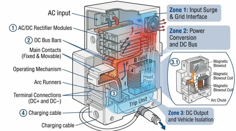
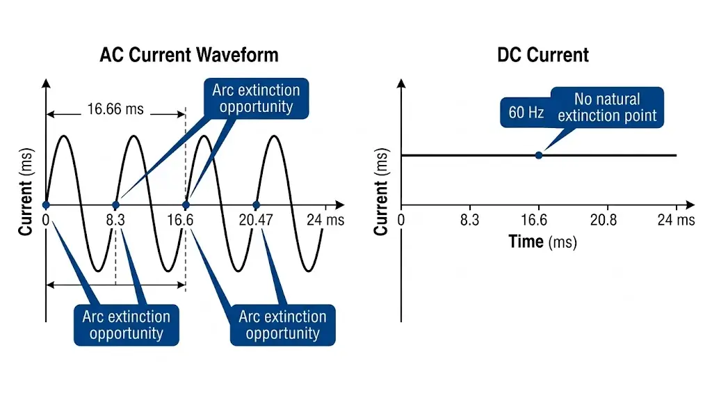
A DC circuit breaker is a protective switching device engineered to interrupt direct current fault conditions in photovoltaic systems, battery energy storage, and EV charging infrastructure. Unlike AC circuit breakers that benefit from current zero-crossing every 8.3 ms (at 60 Hz), DC circuit breakers must forcibly extinguish a sustained arc that can reach temperatures exceeding 6000°C—making their design fundamentally more complex.
This distinction matters. In a 48 MW rooftop solar installation across 12 commercial buildings in Jiangsu Province (2024), properly rated 1000 VDC string-level breakers reduced arc fault duration from 180 ms to under 12 ms, preventing thermal damage to junction boxes and eliminating unplanned maintenance interventions through two summer seasons.
DC circuit breakers for industrial and commercial applications fall under IEC 60947-2, which specifies testing requirements for DC switching capability including making and breaking capacity at rated DC voltage. The core function remains consistent across all types: detect abnormal current, mechanically separate contacts, manage the resulting arc, and restore insulation integrity—all within milliseconds.
The fundamental challenge lies in arc persistence. An AC arc naturally extinguishes at each current zero-crossing, occurring 100–120 times per second. A DC arc sustains continuously until external force intervenes.
This creates three engineering problems:
Modern PV systems operate at string voltages up to 1500 VDC (utility-scale) or 1000 VDC (commercial). Energy storage systems typically run 48–800 VDC, while EV DC fast chargers operate at 200–1000 VDC. A breaker rated for 250 VAC cannot safely interrupt 250 VDC—the DC arc will sustain across the contact gap, potentially causing thermal runaway.
Always verify the DC voltage rating (Ue DC) on the nameplate, not just the AC rating.
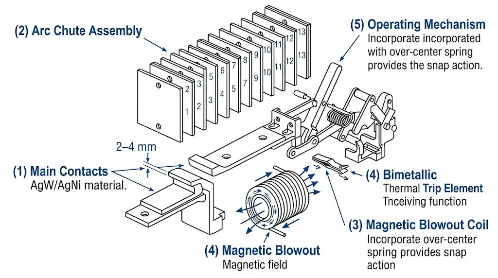
Understanding the internal architecture reveals why DC circuit breakers cost more and weigh more than their AC equivalents.
The primary current-carrying elements use specialized alloys for arc resistance:
Contact gap in DC breakers typically measures 2–4 mm per pole for MCBs and 8–15 mm for MCCBs—significantly wider than AC equivalents to prevent arc re-strike.
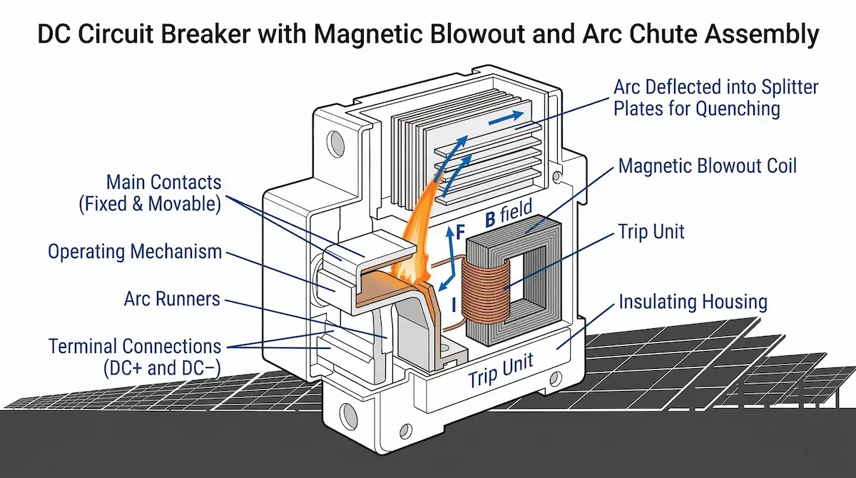
The arc chute is the defining component separating DC breakers from AC designs:
Each splitter plate introduces approximately 20–30 V of arc voltage drop. A 13-plate arc chute adds 260–390 V to total arc voltage, helping force current to zero.
Permanent magnets or electromagnets generate a magnetic field of 50–200 mT perpendicular to the arc column. By Lorentz force (F = BIL), the arc is driven into the arc chute at velocities up to 150 m/s. This action lengthens the arc path, cools it through contact with splitter plates, and accelerates plasma deionization.
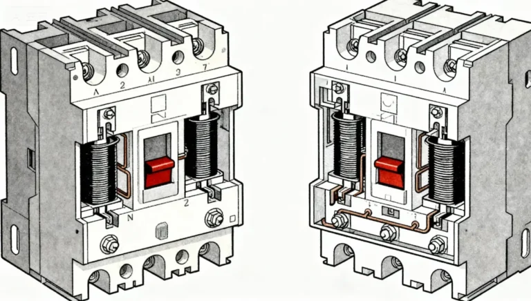
DC breakers employ two primary trip mechanisms working in coordination:
Thermal trip (overload protection) uses a bimetallic strip that heats and bends proportionally to I²t. Trip curves follow IEC 60898-3 classifications: B curve trips at 3–5× In, C curve at 5–10× In, D curve at 10–20× In.
Magnetic trip (short-circuit protection) uses a solenoid coil generating instantaneous trip force when fault current exceeds threshold. Response time: typically 5–20 ms for currents above 10× In.
The toggle mechanism stores energy during ON operation and releases it during tripping. Key elements include over-center spring for snap-action contact separation (minimum 1.2 m/s velocity), trip-free linkage preventing contacts from being held closed during faults, and indication window showing ON/OFF/TRIPPED status.
[Expert Insight: Arc Chute Design]
- Plate count directly correlates with voltage rating—add approximately 2 plates per 100 VDC increase in rated voltage
- Ceramic plates outperform steel in high-frequency switching applications but cost 40–60% more
- Arc chute contamination from environmental dust reduces breaking capacity by up to 15%—specify IP65 minimum for outdoor installations
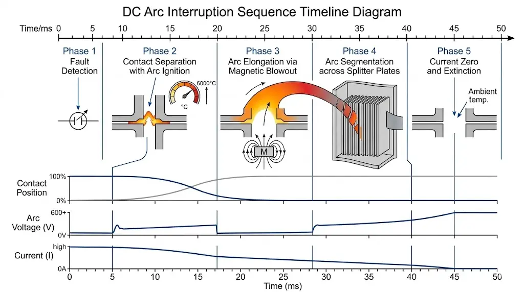
The interruption sequence occurs in approximately 10–50 ms for MCBs and 20–80 ms for MCCBs. Each phase builds on the previous one.
Thermal element begins heating (overload) or magnetic coil energizes (short circuit). For a 10 kA fault on a 63 A breaker, magnetic trip initiates within 3 ms.
Trip mechanism releases. Spring drives contacts apart at 1.2–2.5 m/s. Arc ignites immediately—initial arc voltage approximately 20–40 V.
Magnetic blowout drives arc into the arc chute. Arc length increases from initial 2 mm to 50–100 mm. Arc voltage rises to 300–600 V.
Arc enters splitter plates, dividing into 10–20 series arcs. Total arc voltage now exceeds system voltage (e.g., 800 V arc voltage vs. 600 VDC system).
When arc voltage exceeds system voltage, current is forced toward zero. Final extinction occurs as arc plasma cools below ionization temperature (~4000 K). Post-arc resistance must exceed 1 MΩ within 100 ms to prevent re-strike.
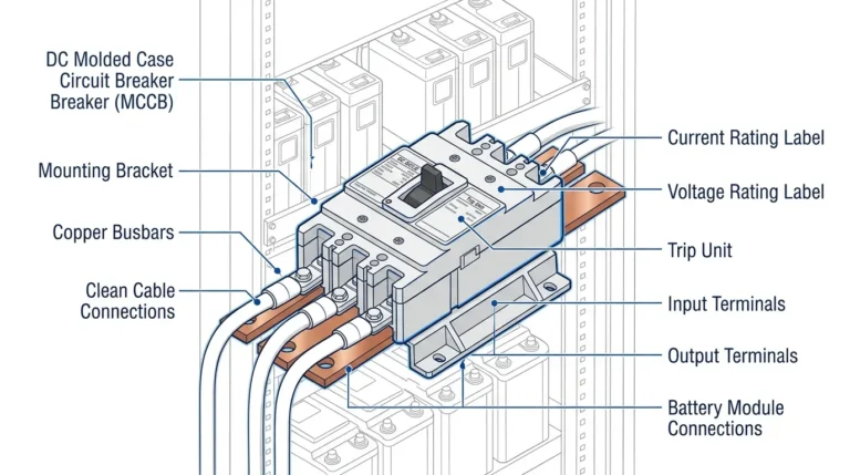
The choice between miniature circuit breakers (MCB) and molded case circuit breakers (MCCB) depends on your system’s current capacity and protection requirements.
| Parameter | DC MCB | DC MCCB |
|---|---|---|
| Current Range | 1–63 A | 16–1250 A |
| Voltage Rating | Up to 1000 VDC | Up to 1500 VDC |
| Breaking Capacity | 6–10 kA | 10–50 kA |
| Trip Adjustment | Fixed | Adjustable (thermal & magnetic) |
| Typical Application | String protection | Main disconnect |
| Mounting | DIN rail (35 mm) | Panel mount or DIN rail |
For string-level protection in a 1000 VDC PV system with 15 A string current, a 2-pole DC MCB rated 1000 VDC / 20 A / 10 kA provides appropriate protection. For the main DC disconnect ahead of a 500 kW central inverter, a DC MCCB rated 1500 VDC / 800 A / 50 kA with adjustable trip settings offers necessary capacity and selectivity.
[Expert Insight: Selection Pitfalls]
- Never size breakers based solely on cable ampacity—match to actual load current plus 25% margin
- MCCBs with electronic trip units offer ±5% accuracy versus ±20% for thermal-magnetic units
- In battery storage applications, verify bidirectional rating—some DC breakers are polarity-sensitive
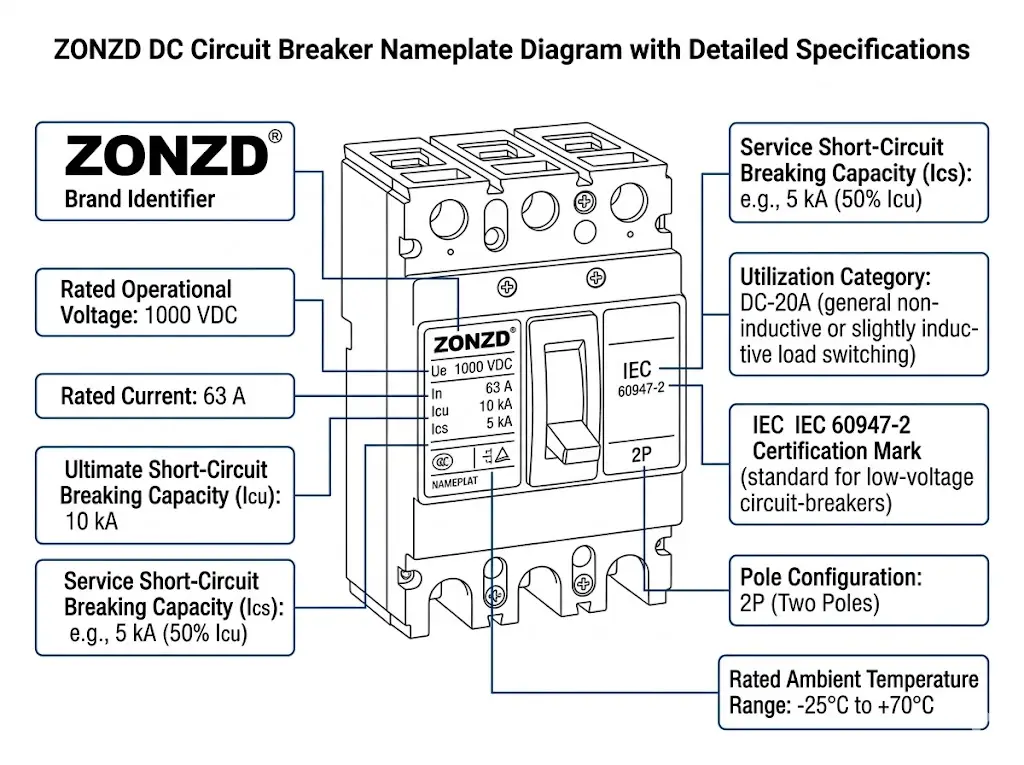
Must equal or exceed maximum system voltage under all conditions. For PV systems, calculate Voc_max using temperature coefficients—a 1000 VDC nominal system may reach 1100 VDC at -10°C. Specify breakers with Ue ≥ 1100 VDC or apply appropriate derating.
Icu (ultimate breaking capacity) indicates the breaker can interrupt but may not remain operational. Ics (service breaking capacity) means it can interrupt and continue functioning. For PV applications, prospective fault current depends on inverter contribution and parallel string count—typically 6–15 kA for string inverters, 20–50 kA for central inverters.
Per IEC 60947-2: DC-20A covers resistive loads, DC-20B covers inductive loads, DC-21A and DC-21B address frequent switching applications. PV systems typically fall under DC-20A; ESS with contactors may require DC-21B rating.
Unlike AC systems, DC polarity matters. A 2-pole breaker interrupts both positive and negative—standard for most DC applications. For 1000 VDC ungrounded PV systems, a 2-pole breaker with 500 VDC per pole rating (series-connected internally) provides full system voltage interruption.
When combining DC breakers with DC fuses for backup protection, ensure fuse I²t is lower than breaker thermal damage threshold.
DC breakers serve multiple protection points in PV installations: string protection for individual string isolation in PV combiner boxes, combiner output disconnect between combiner and inverter, and inverter DC input disconnect per NEC 690.15 requirements.
In a 30 MW ground-mount installation in Ningxia (2023), string-level DC MCBs enabled maintenance crews to isolate individual strings in under 2 minutes—compared to 15+ minutes when relying solely on combiner-level disconnects.
Battery systems require DC breakers rated for bidirectional current flow during charge/discharge cycles. Additional considerations include battery short-circuit current (can exceed 20 kA for lithium-ion banks), arc flash hazard from sustained DC fault current, and remote trip capability for BMS integration.
DC fast chargers (50–350 kW) incorporate DC breakers for rectifier output protection between AC/DC converter and charging cable, ground fault detection for insulation failures, and emergency disconnect capability during faults.
Selecting the right DC circuit breaker requires matching voltage ratings, breaking capacity, and trip characteristics to your specific system parameters. Undersized breakers create safety hazards; oversized units waste budget and may not provide adequate protection sensitivity.
Sinobreaker’s DC circuit breaker portfolio spans from 6 A string-level MCBs to 1250 A main disconnect MCCBs, all tested to IEC 60947-2 and certified for photovoltaic, energy storage, and EV charging applications.
For system design support or product selection assistance, contact our engineering team with your project specifications.
DC circuit breakers use specialized arc chutes and magnetic blowout systems to force arc extinction, while AC breakers rely on natural current zero-crossings occurring 100–120 times per second to extinguish arcs with simpler designs.
No. AC breakers lack the arc interruption capability for sustained DC arcs and will likely fail to clear faults, creating fire and equipment damage risks even at equivalent voltage ratings.
DC MCBs typically cover up to 1000 VDC for commercial solar applications, while DC MCCBs extend to 1500 VDC for utility-scale photovoltaic and high-voltage energy storage installations.
Magnetic trip response typically occurs within 5–20 ms for fault currents exceeding 10× rated current, with total arc extinction completed in 10–50 ms for MCBs and 20–80 ms for MCCBs.
Most DC breakers are position-sensitive due to magnetic blowout direction—always follow manufacturer markings for line/load terminals and maintain vertical mounting within ±5° unless horizontal operation is explicitly rated.
Calculate prospective fault current based on your system configuration—typically 6–15 kA for string inverter installations and 20–50 kA for central inverter systems with multiple parallel combiners.
Perform visual inspection and terminal torque verification annually; conduct functional trip testing every 24–36 months. Replace any breaker showing visible arc damage, discoloration, or failing trip time tests.