Address
304 North Cardinal
St. Dorchester Center, MA 02124
Work Hours
Monday to Friday: 7AM - 7PM
Weekend: 10AM - 5PM
Address
304 North Cardinal
St. Dorchester Center, MA 02124
Work Hours
Monday to Friday: 7AM - 7PM
Weekend: 10AM - 5PM

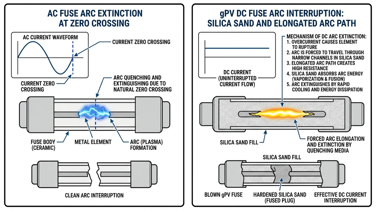
DC fuse failure in solar installations occurs when a fuse element melts under sustained overcurrent or fault conditions — but unlike AC systems, the resulting arc cannot self-extinguish at a natural current zero crossing. In photovoltaic circuits, this DC arc persists, sustains temperatures above 5000°C, and can cause catastrophic damage if the fuse lacks proper DC interrupting capacity.
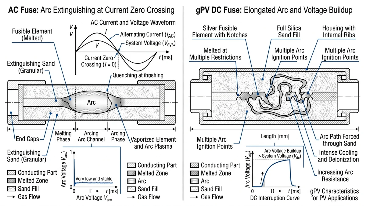
AC current reverses polarity at 50 or 60 Hz, creating a natural zero crossing every 8–10 ms where arc plasma cools and the arc extinguishes. DC current in a PV string is continuous and unidirectional. When a fuse element ruptures in a 1000 VDC or 1500 VDC string circuit, the arc voltage must be driven above system voltage entirely through the fuse’s internal arc-quenching medium — typically silica sand in a gPV-rated fuse — before current interruption completes.
This is why IEC 60269-6 governs fuses specifically for photovoltaic applications, requiring gPV fuses to demonstrate full breaking capacity at rated DC voltage with controlled arc energy dissipation. A standard AC fuse installed in a DC string circuit may interrupt successfully at low fault currents but fail violently at higher prospective fault currents, because its arc chamber geometry and fill material are not engineered for sustained DC arc elongation.
In a 60 MW ground-mount installation in Hebei Province (2023), post-fault inspection revealed that six string fuses had ruptured without fully interrupting current — each was an AC-rated component installed by a subcontractor unfamiliar with DC protection requirements. Arc damage extended to the combiner box busbars, requiring full replacement of two PV combiner boxes.
String circuits in utility-scale PV systems typically sustain 1.25–1.56 × Isc under maximum power point conditions, and prospective fault current at the combiner input can reach 2–3 × Isc for 3–5 seconds before protective actuation — a window where an undersized or AC-rated fuse is most likely to fail destructively.
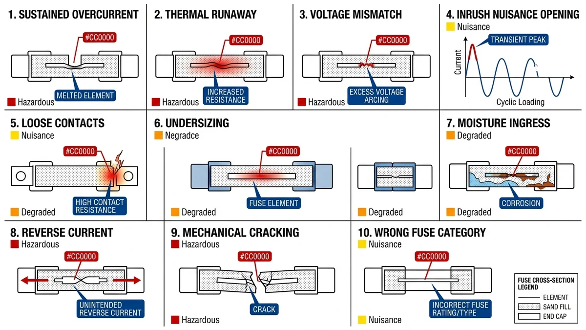
Most field failures are repeatable patterns tied to sizing, heat, contamination, or installation quality. Use the cause-symptom-fix structure below to narrow root cause quickly.
Cause: Partial shading or soiling on one string forces reverse current through adjacent strings, pushing fuse current above rated Isc.
Field symptom: fuse opens intermittently during peak irradiance; inverter logs show one MPPT channel dropping offline between 11:00–14:00.
Fix: verify string Isc balance with a clamp meter; replace undersized fuses with gPV-rated units at 1.5× Isc per IEC 60269-6, and inspect the PV combiner box for corroded busbars.
Cause: Combiner boxes mounted on south-facing walls in direct sun routinely reach 70–80°C internal air temperature in summer. Fuse elements derate at elevated temperature — a 10°C rise above 40°C reference typically reduces continuous current capacity by 5–10%.
Field symptom: fuses blow on hot afternoons despite normal irradiance; enclosure surface temperature exceeds 60°C by touch.
Fix: relocate or shade the combiner box, apply thermal derating per manufacturer curves, and upgrade to fuses with a higher temperature class.
Cause: Technicians install AC-rated or general-purpose DC fuses in 1000 VDC or 1500 VDC string circuits.
Field symptom: fuse body cracks or end caps eject violently on first fault; visible scorch marks on fuse holder.
Fix: replace immediately with IEC 60269-6 gPV fuses rated at or above the open-circuit string voltage. See the DC fuse selection guide for voltage class matching.
Cause: Capacitive inrush when a string reconnects after cloud transients can produce current spikes 3–5× Isc lasting 2–10 ms. Fast-acting fuses with low I²t ratings open on these transients even though no real fault exists.
Field symptom: fuses blow repeatedly with no measurable insulation fault; replacement fuses fail within days.
Fix: switch to time-delay gPV fuses with higher I²t withstand, or install a DC switch disconnector with pre-insertion resistance to limit inrush.
Cause: Vibration, thermal cycling, and humidity loosen fuse clips or oxidize contact surfaces, increasing resistance.
Field symptom: fuse holder runs noticeably hotter than adjacent holders; IR camera shows a hot spot at the contact interface; voltage drop across the fuse exceeds 100 mV at rated current.
Fix: torque fuse holder terminals to manufacturer specification, clean contacts with isopropyl alcohol, and replace holders showing pitting or discoloration.
Cause: Designers select fuse current equal to Isc instead of applying the 1.25–1.56× Isc multiplier required for string overcurrent protection.
Field symptom: fuses blow during normal operation on high-irradiance days; no fault is found after replacement.
Fix: recalculate the required fuse rating using Isc at STC × 1.25 minimum, and cross-reference with the gPV fuse series for compliant current ratings.
Cause: Combiner boxes with degraded IP sealing allow condensation or rain ingress. Moisture bridges fuse terminals and accelerates corrosion of the silver-alloy fuse element.
Field symptom: fuse element shows green or white corrosion deposits; insulation resistance between string conductors drops below 1 MΩ.
Fix: restore enclosure IP54 or IP65 rating, replace corroded fuses and holders, and add desiccant packs inside the enclosure. Review installation practices in the PV system protection error guide.
Cause: A failed short-circuit bypass diode in a module allows reverse current to flow back through the string fuse continuously, even at night.
Field symptom: fuse on one string runs warm at night when all others are cold; module-level monitoring shows one module with anomalous forward voltage.
Fix: identify and replace the failed module or bypass diode; verify fuse current rating accounts for maximum reverse current per IEC 62548-1 Clause 9.
Cause: Technicians over-tighten fuse caps or drop ceramic fuse bodies, creating micro-cracks in the fuse tube that are invisible externally.
Field symptom: fuse fails immediately or within the first week of commissioning; no electrical fault is detected on the string.
Fix: implement a pre-installation visual and continuity check on every fuse; train crews on correct insertion torque. The professional PV fuse installation guide covers handling procedures in detail.
Cause: General-purpose gG or gL fuses are installed instead of gPV fuses. gG fuses are not designed for the unidirectional DC fault profile or the extended arc energy of PV strings.
Field symptom: fuse clears slowly on fault, allowing arc energy to damage the fuse holder and adjacent wiring; post-fault inspection shows melted holder insulation.
Fix: specify only IEC 60269-6 gPV fuses for all string and combiner-level protection in PV systems.
[Expert Insight]
– Compare suspect string currents against neighboring strings at the same irradiance before replacing hardware; imbalance often exposes mismatch or reverse-current problems faster than insulation testing.
– If one holder is more than 10°C hotter than adjacent holders under similar load, inspect the clip tension and terminal torque before blaming the fuse element.
– Repeated “mystery” fuse operation over a few hot afternoons usually points to derating, enclosure heat, or undersizing rather than a hard short.
Once a fuse has opened or started running hot, a disciplined sequence prevents misdiagnosis and repeat outages. The fastest field teams follow the same four checks every time: visual condition, electrical continuity, thermal behavior, and fault-energy fit.
Start with a full visual check before touching any test equipment. Look for discoloration on the fuse body or end caps, carbon tracking on the fuse holder contacts, and signs of moisture ingress in the combiner box. Also check for loose terminal connections — elevated contact resistance generates localized heat that degrades the fuse element over time without triggering an immediate overcurrent event.
De-energize the string and use a calibrated multimeter set to resistance mode. A healthy fuse reads below 1 Ω across its terminals. A reading above 10 Ω or an open circuit confirms element failure. Cross-reference with adjacent string fuses to establish a baseline — resistance variance greater than 0.5 Ω between identical fuses in the same combiner box warrants further investigation even if the fuse has not fully opened.
Infrared scanning under live load conditions is one of the most reliable non-invasive ways to catch pre-failure fuses. A temperature differential of more than 10°C between a fuse position and its reference baseline indicates abnormal resistive heating. In a 35 MW ground-mount installation in Hebei Province, thermographic surveys identified 14 thermally stressed string fuses operating at 38–52°C above ambient — all were replaced before any string went offline.
If the fuse has blown, compare the fault event data from your inverter or monitoring system against the fuse’s published I²t let-through rating. The melting I²t value defines the minimum energy (in A²·s) required to open the fuse element. If the recorded fault current squared multiplied by fault duration falls below the fuse’s rated melting I²t, the fuse was likely undersized for the application — a selection error, not a component defect. For 1000 VDC string circuits, typical melting I²t values for 15 A gPV fuses range from 200–800 A²·s depending on manufacturer and fuse class.
If the measurements point back to a selection error, review rated current, voltage class, and fault-energy coordination before energizing the circuit again.
Most recurring fuse problems can be prevented long before commissioning by checking a short list of application parameters against actual site conditions. Selection discipline matters more in PV than in general industrial DC because the source is continuous, the voltage is high, and reverse current can come from parallel strings.
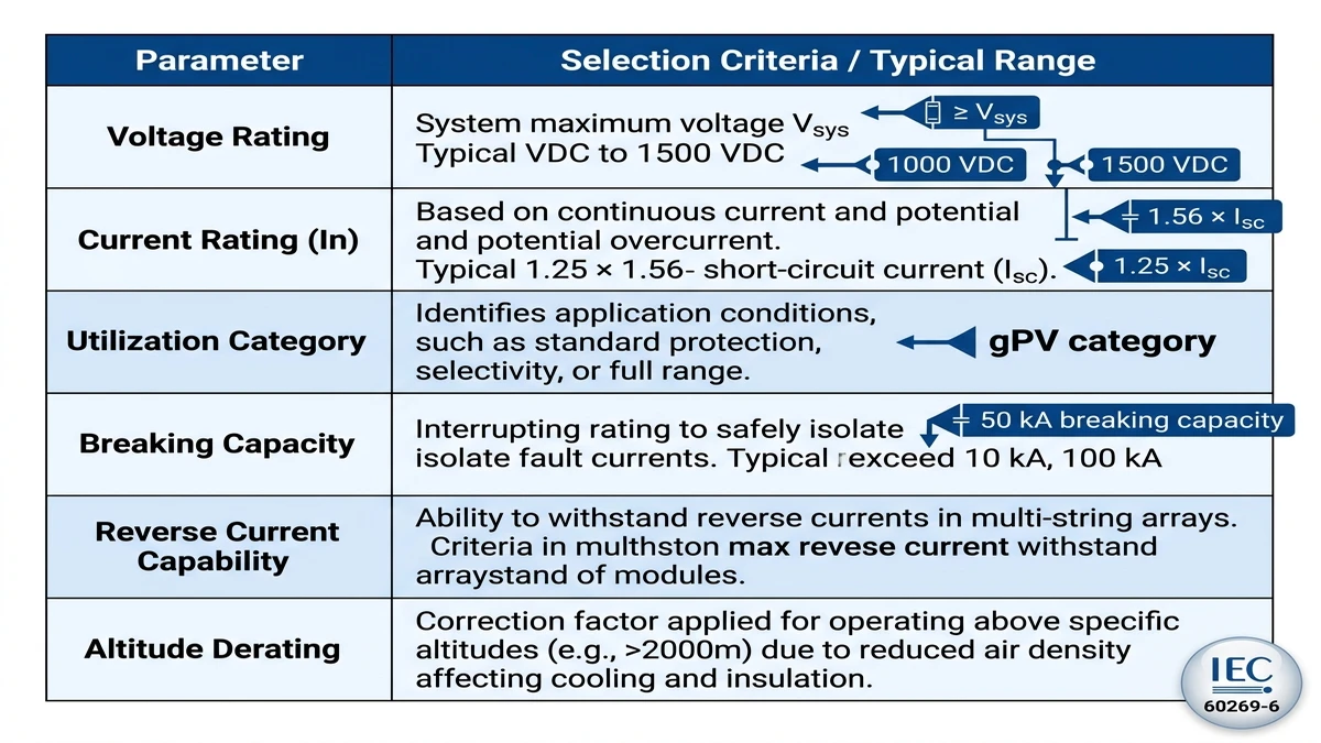
| Parameter | Selection Criteria | Typical Range / Threshold |
|---|---|---|
| Voltage Rating | Must exceed maximum open-circuit string voltage including temperature coefficient | 1000 VDC or 1500 VDC per IEC 60269-6 |
| Current Rating | Set at 1.56 × Isc per string; never size down for cost | 10 A – 32 A for residential/commercial strings |
| Utilization Category | gPV category mandatory for PV DC circuits; gG/gL are unsuitable | gPV (IEC 60269-6) |
| Breaking capacity | Must exceed prospective short-circuit current at the combiner bus | Typically 20 kA – 50 kA in utility-scale systems |
| Reverse Current | Bidirectional fuses required where parallel strings can back-feed | Rated for reverse Isc × number of parallel strings |
| Altitude Derating | Above 2000 m, dielectric strength drops; apply derating factor per IEC 60664-1 | Derate voltage rating ~1.25% per 100 m above 2000 m |
A gPV fuse is engineered specifically for the flat DC current profile of photovoltaic sources, where fault current does not self-extinguish. Using a standard gG fuse in a 1000 VDC string circuit is a common cause of fuse body rupture and combiner box damage. IEC 60269-6 defines gPV performance requirements, including DC breaking behavior, time-current characteristics, and suitability for reverse-current conditions found in PV arrays. For reference, the IEC standards catalog is available at https://www.iec.ch.
In one 62 MW ground-mount installation in Hebei Province, replacing undersized gG fuses with correctly rated gPV fuses at 1.56 × Isc eliminated recurring nuisance trips across 18 combiner boxes within the first operating quarter.
[Expert Insight]
– Always calculate maximum cold-weather Voc before confirming voltage class; many borderline selections fail because designers use nominal string voltage instead of worst-case open-circuit voltage.
– In parallel-string arrays, check reverse-current exposure as carefully as forward current rating; a fuse can be “correct” for load current and still be wrong for backfeed conditions.
– For high-altitude sites, verify both fuse voltage derating and holder insulation performance as a matched pair.
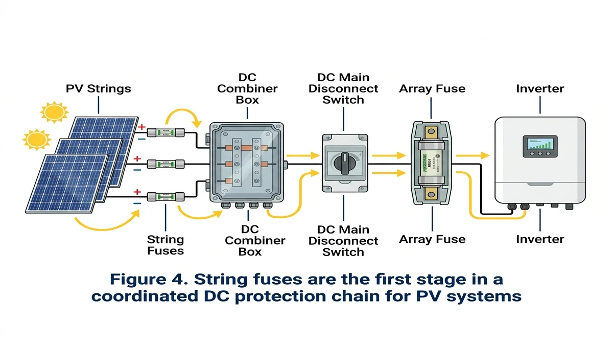
Fuse troubleshooting gets easier when you view the string fuse as part of a coordinated protection path rather than an isolated component. Its job is to stop low-level reverse-current and inter-string faults before they escalate into busbar, disconnect, or inverter damage.
A properly designed PV system routes fault current through four sequential protection stages:
Each stage handles a different fault magnitude. String fuses respond first to reverse current and inter-string faults at the lowest current level. If a string fuse fails to clear, the fault escalates to the combiner box level, where a DC switch disconnector or DC MCCB must handle much higher prospective fault current.
In a 1500 VDC architecture, a single failed string fuse can expose the combiner bus to sustained reverse current from multiple parallel strings. In one 60 MW ground-mount installation in Hebei Province, maintenance logs showed that three undetected open-circuit string fuses caused adjacent strings to carry 140% of rated current for several weeks before thermal damage appeared at the combiner terminals.
This cascade risk is why gPV fuses must be correctly rated for both voltage and current-limiting class. A fuse that opens but does not interrupt arc current at 1000 VDC or 1500 VDC provides no real protection — it simply removes itself while the fault path remains active.
After diagnosis and failure analysis, the final step is turning those lessons into a repeatable specification standard.
Use this checklist before finalizing any fuse selection for a PV string or combiner circuit:
In a 35 MW ground-mount installation in Hebei Province, replacing standard gG fuses with properly rated gPV fuses reduced nuisance string outages by an estimated 60% over the first operating year.
The GPV fuse series is built to IEC 60269-6, with ratings available from 2 A to 32 A at up to 1500 VDC. If you are auditing an existing installation for fuse-related failures, the DC fuse product overview and the PV system protection error reference are practical starting points before you pull any hardware.
Because DC current does not pass through a natural zero crossing, the fuse has to extinguish the arc entirely on its own. If the fuse is not designed for PV DC duty, the arc can persist and damage the holder or enclosure.
Undersized current ratings and high enclosure temperature are two of the most frequent causes. In many cases, the string is healthy and the fuse is simply operating too close to its derated limit.
No. A gG fuse is not intended for the DC fault characteristics of photovoltaic strings and may clear too slowly or fail to interrupt safely.
Check for localized heating at the holder, discolored clips, or a temperature rise compared with neighboring fuse positions. A thermal camera often reveals contact problems before continuity testing does.
The selected current rating should be based on the string short-circuit current with the required design multiplier, while the voltage rating must exceed maximum string Voc. The final choice also has to match reverse-current exposure and breaking-capacity requirements.
Yes. Poor clip tension, corrosion, or loose terminals can overheat a good fuse and create a repeat failure pattern that looks like an overcurrent issue.
Not until the root cause is confirmed. Replacing with the same part without checking current sizing, temperature, and holder condition often leads to another outage.


