Address
304 North Cardinal
St. Dorchester Center, MA 02124
Work Hours
Monday to Friday: 7AM - 7PM
Weekend: 10AM - 5PM
Address
304 North Cardinal
St. Dorchester Center, MA 02124
Work Hours
Monday to Friday: 7AM - 7PM
Weekend: 10AM - 5PM


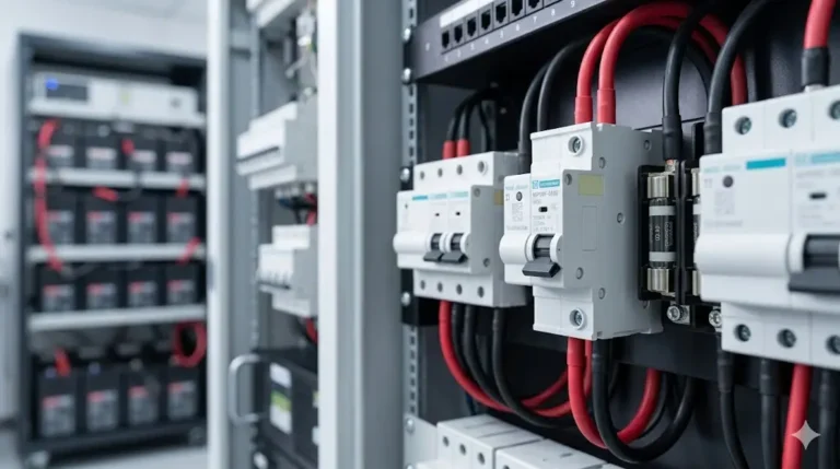
A DC circuit breaker panel serves as the central nervous system for any DC electrical installation—whether solar photovoltaic systems, marine vessels, RVs, or off-grid battery banks. This comprehensive guide covers professional-grade panel selection, NEC-compliant installation procedures, and optimal circuit configuration.
Unlike traditional AC panels, DC breaker panels must handle unique challenges:
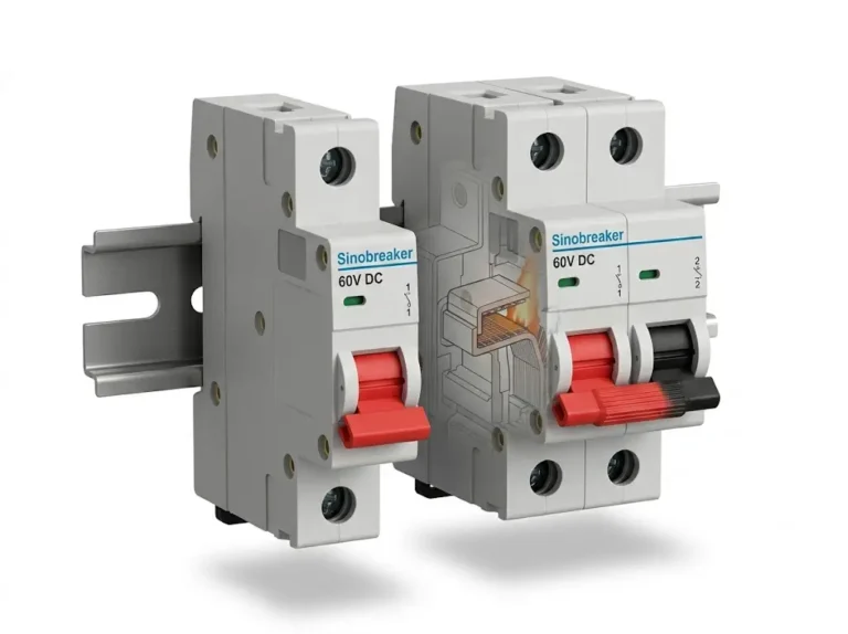
– Arc suppression: DC arcs don’t self-extinguish like AC
– Polarity management: Positive/negative bus configuration
– High current capacity: 12-48V systems require larger conductors
– Environmental protection: Marine/outdoor installations need weatherproofing
– Expandability: Future circuit additions require planning
Key Applications:
– Solar PV system distribution (residential 5-15kW)
– Marine vessel electrical systems (sailboats, yachts, powerboats)
– RV and camper electrical panels
– Off-grid battery storage systems
– Electric vehicle charging stations
– Telecommunications backup power
– Industrial DC equipment distribution
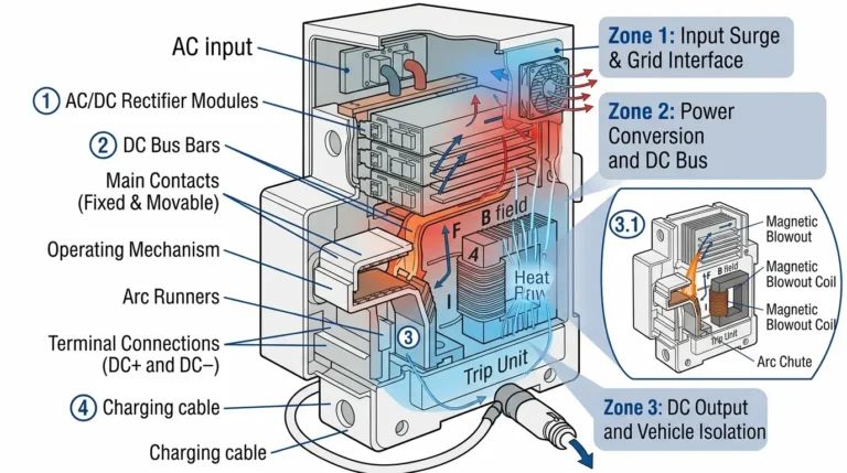
1. Main Enclosure
– NEMA-rated or IP-rated weatherproof box
– Dimensions: 12″×16″ to 24″×36″ typical
– Materials: Powder-coated steel, stainless steel, or aluminum
– Door with gasket seal (marine/outdoor)
2. Positive Busbar
– Copper or tinned copper construction
– Rating: 100A to 400A capacity
– Multiple circuit breaker mounting positions
– Insulated to prevent accidental shorts
3. Negative Busbar (Return Path)
– Equal or greater ampacity than positive bus
– Bonded to ground in system grounding point
– Separate terminal blocks for each circuit return
4. Ground Busbar
– Bonded to enclosure and system ground
– Required for safety per NEC Article 250
– Green/bare copper conductors only
5. Circuit Breaker Mounting Rails
– DIN rail (35mm standard) or custom mounting
– Positions for 4-24 breakers typical
– Expansion capabilities for future circuits
6. Labeling and Documentation
– Durable circuit labels (laminated or engraved)
– One-line diagram inside door
– Voltage rating and system specifications
#### Type 1: Solar PV Distribution Panels
– Voltage: 12V, 24V, 48V DC (600V for utility-scale)
– Breaker Count: 6-12 circuits typical
– Special Features: Combiner functionality, surge protection integration
– Standards: NEC Article 690 compliance
– Typical Layout:
– Main battery disconnect (150-300A)
– Solar charge controller circuit (60-100A)
– Inverter circuit (150-200A)
– Load circuits (15-30A each)
#### Type 2: Marine Distribution Panels
– Voltage: 12V or 24V DC (rarely 48V)
– Breaker Count: 8-16 circuits
– Special Features: ABYC compliance, ignition protection, corrosion resistance
– Ratings: IP66/IP67 for exposed installations
– Typical Layout:
– Navigation lights (10A)
– Bilge pumps (15-20A)
– Cabin lights (15A)
– Electronics (10-20A)
– Freshwater pump (10A)
– Windlass (60-100A dedicated)
#### Type 3: RV/Camper Panels
– Voltage: 12V DC (almost universal)
– Breaker Count: 6-12 circuits
– Special Features: Converter integration, dual battery capability
– Typical Layout:
– Converter/charger output (40-60A)
– Interior lights (15A)
– Water pump (15A)
– Furnace blower (20A)
– Refrigerator DC mode (15A)
– Slide-out motors (30A)
– Inverter (150A dedicated)
#### Type 4: Industrial/Telecom Panels
– Voltage: 48V DC most common (also 24V, 125V)
– Breaker Count: 12-24+ circuits
– Special Features: Remote monitoring, redundant buses
– Standards: NEMA TS-2 (traffic), IEEE 1375 (telecom)

Step 1: Calculate Total Load Current
Example Solar/Battery System:
- Inverter: 3000W ÷ 48V = 62.5A
- Charge Controller: 3200W array ÷ 48V = 66.7A
- LED Lighting: 100W ÷ 48V = 2.1A
- Water Pump: 300W ÷ 48V = 6.3A
- Electronics: 150W ÷ 48V = 3.1A
- Refrigerator: 600W ÷ 48V = 12.5A
Total: 153.2A
Step 2: Apply NEC 125% Rule
Main Busbar Rating = Total Load × 1.25
= 153.2A × 1.25 = 191.5A
Select: 200A busbar minimum
Step 3: Count Required Circuit Positions
– Dedicated circuits for large loads (inverter, charger)
– Grouped circuits for similar small loads
– 20-30% spare positions for future expansion
– Example: 6 active + 2 spare = 8-position minimum panel
Step 4: Voltage Rating Selection
| System Nominal Voltage | Required Panel Rating |
|---|---|
| 12V | 32V DC minimum |
| 24V | 50V DC minimum |
| 48V | 80V DC minimum |
| 120V | 150V DC minimum |
| 600V | 1000V DC minimum |
NEMA Ratings (North America):
– NEMA 1: Indoor, general purpose (dry locations)
– NEMA 3R: Outdoor, rain-tight (RVs, outdoor solar)
– NEMA 4: Outdoor, watertight (marine, exposed)
– NEMA 4X: Corrosion-resistant (salt water marine)
IP Ratings (International):
– IP20: Indoor only, basic protection
– IP54: Outdoor, dust/splash protected
– IP65: Outdoor, dust-tight, water jet protected
– IP67: Marine, dust-tight, temporary immersion (30 min at 1m)
Material Selection by Environment:
| Environment | Recommended Material | Coating |
|---|---|---|
| Indoor residential | Powder-coated steel | Standard |
| Outdoor solar | Aluminum or stainless | UV-resistant |
| Freshwater marine | Powder-coated steel | Marine-grade |
| Saltwater marine | 316 stainless steel | Electropolished |
| Tropical/humid | Stainless or aluminum | Conformal coated internals |

1. Location Selection Criteria
Accessibility Requirements:
– Working clearance: 30″ width × 36″ depth minimum (NEC 110.26)
– Height: 4-6.5 feet above floor (comfortable reach)
– Illumination: Minimum 100 lux (10 foot-candles)
– Clear of obstructions within working space
Environmental Considerations:
– Temperature range: -20°C to 50°C operating range typical
– Avoid direct sunlight (UV degradation, heating)
– Minimum 6 inches from heat sources
– Dry location preferred; wet-rated if necessary
– Adequate ventilation for heat dissipation
Proximity Requirements:
– Close to battery bank (minimize main conductor length)
– Near loads to minimize branch circuit wire runs
– Accessible for maintenance and troubleshooting
– Protected from physical damage
2. Wire Sizing Calculations
NEC Ampacity Table (75°C rated wire, 30°C ambient):
| Wire Gauge | Copper Ampacity | Aluminum Ampacity |
|---|---|---|
| 14 AWG | 20A | 15A |
| 12 AWG | 25A | 20A |
| 10 AWG | 35A | 30A |
| 8 AWG | 50A | 40A |
| 6 AWG | 65A | 50A |
| 4 AWG | 85A | 65A |
| 2 AWG | 115A | 90A |
| 1/0 AWG | 150A | 120A |
| 2/0 AWG | 175A | 135A |
| 3/0 AWG | 200A | 155A |
| 4/0 AWG | 230A | 180A |
Derating Factors:
– More than 3 current-carrying conductors in conduit: 0.8× (4-6 wires), 0.7× (7-9 wires)
– High ambient temperature (>30°C): See NEC Table 310.15(B)(2)(a)
– Voltage drop limitation: Typically 3% max for branch circuits
Example Main Conductor Sizing:
System: 48V DC, 200A main breaker
Required ampacity: 200A × 1.25 = 250A (continuous load factor)
Conductor: 300 kcmil copper (wet location) = 285A capacity
Voltage drop check (20 feet):
Drop = (2 × 20 ft × 200A × 0.0162 Ω/1000ft) / 1000 = 0.13V (0.27% - OK)
Tools Required:
– Power drill with appropriate bits
– Torque screwdriver (in-lbs and ft-lbs ranges)
– Wire strippers (10-18 AWG range)
– Hydraulic crimper for large terminals
– Multimeter (DC voltage/current)
– Insulation resistance tester (megohmmeter)
– Cable lugs and heat shrink
– Labeling machine
– Level
– Stud finder
Step 1: Enclosure Mounting
1. Locate mounting position (accessibility + proximity)
2. Check for studs/structural supports behind
3. Mark mounting holes with template
4. Drill pilot holes
5. For metal buildings: Use self-tapping screws
6. For wood: Use 3" lag bolts into studs
7. For concrete/masonry: Use expansion anchors
8. Level enclosure before final tightening
9. Torque mounting hardware to specification
Step 2: Grounding and Bonding
1. Install ground busbar inside enclosure
2. Bond ground busbar to enclosure with 6 AWG minimum
3. Run equipment grounding conductor to main system ground
4. Verify <25 ohms resistance to earth ground (NEC 250.53)
5. Label ground wire with green tape or sleeve
6. Torque ground connections: 120 in-lbs typical
Step 3: Main Conductor Installation
1. Route main positive from battery to panel location
2. Install main disconnect breaker at battery (within 7")
3. Strip wire insulation (1/2" for compression lugs)
4. Crimp compression lug onto conductor
5. Apply heat shrink over crimp connection
6. Connect to main breaker input terminal
7. Torque to specification (200 in-lbs for 1/0 AWG typical)
8. Connect breaker output to positive busbar
9. Route main negative to negative busbar
10. Crimp and connect negative conductor
11. Apply dielectric grease to all connections
Step 4: Circuit Breaker Installation
1. Snap DIN rail into enclosure (if not pre-installed)
2. Install circuit breakers on positive busbar taps
3. Verify proper amperage rating for each circuit
4. Arrange in logical order (high to low current)
5. Leave positions for future expansion
6. Torque busbar connections per manufacturer spec
7. Verify breakers reset smoothly
Step 5: Branch Circuit Wiring
1. Route each branch circuit from panel to load
2. Label wire at both ends with circuit number
3. Strip and crimp appropriate terminals
4. Connect to load side of circuit breakers
5. Route return (negative) wires to negative busbar
6. Torque connections: 80-120 in-lbs for 10-14 AWG
7. Dress wires neatly with tie wraps
8. Maintain minimum bend radius (10× wire diameter)
Step 6: Labeling and Documentation
1. Label each breaker with circuit name and amperage
2. Create one-line diagram showing all connections
3. Laminate diagram and affix inside door
4. Mark voltage rating on enclosure exterior
5. Apply warning labels:
   - "DC VOLTAGE - DO NOT USE AC BREAKERS"
   - System voltage (e.g., "48V DC SYSTEM")
   - Main disconnect location
6. Record wire gauges and breaker ratings in documentation
Step 7: Testing and Commissioning
1. Visual inspection: No exposed conductors, proper torque
2. Insulation resistance test: >1 MΩ positive to ground
3. Continuity test: Verify negative return paths
4. Voltage test: Measure at busbar (should match battery)
5. Individual circuit test:
   - Reset each breaker
   - Measure voltage at load
   - Verify proper operation of load
6. Load test: Energize all circuits simultaneously
7. Thermal imaging (if available): Check for hot spots
8. Document all test results
Strategy 1: By Load Type
– Critical/Life Safety (bilge pumps, navigation lights): Top positions
– Daily Use (lights, water pump): Middle positions
– Convenience/Comfort (entertainment, USB ports): Lower positions
– High Current (inverter, charger): Dedicated positions with heavy wire
Strategy 2: By Usage Pattern
– Always-On (refrigerator, monitoring): Rarely tripped
– Intermittent (lights, water pump): Frequent use
– Seasonal (heating, cooling): Periodic use
– Emergency (backup systems): Rarely used
Strategy 3: By Person/Zone
– Cabin 1 circuits
– Cabin 2 circuits
– Galley/kitchen circuits
– Navigation/helm circuits
– Engine room circuits
| Load Type | Typical Power | 12V Current | 24V Current | 48V Current | Breaker Size |
|---|---|---|---|---|---|
| LED Lighting (whole system) | 100W | 8.3A | 4.2A | 2.1A | 15A |
| Freshwater Pump | 300-500W | 25-42A | 12-21A | 6-10A | 15-20A (12V) |
| Refrigerator (DC) | 600-900W | 50-75A | 25-37A | 12-19A | 20-30A (12V) |
| Inverter 1500W | 1500W | 125A | 62A | 31A | 150A (12V) |
| Inverter 3000W | 3000W | 250A | 125A | 62A | 80A (48V) |
| Solar Charge Controller | Varies by array | 60-100A | 40-60A | 30-40A | Match controller rating |
| RV Slide-Out Motor | 800W | 67A | 33A | 17A | 80A (12V) |
| Windlass (marine) | 1500W | 125A | 62A | 31A | 150A (12V) |
| Bilge Pump | 150-300W | 12-25A | 6-12A | 3-6A | 20A (12V) |
125% Rule Applied:
For continuous loads (>3 hours), multiply calculated current by 1.25 to determine minimum breaker rating.
Maximum Acceptable Voltage Drop:
– Main conductors (battery to panel): 1%
– Branch circuits (panel to load): 3%
– Combined: 4% total system
Mitigation Strategies:
1. Locate panel close to battery: Minimize main conductor length
2. Upsize main conductors: Lower resistance reduces drop
3. Use copper vs. aluminum: Copper has 60% of aluminum resistance
4. Minimize branch circuit length: Route loads near panel
5. Use higher system voltage: 48V vs. 12V reduces current 4×
Voltage Drop Calculation Tool:
Drop (V) = (2 × Length in feet × Current in A × Wire Resistance per 1000 ft) / 1000Example: 12V system, 10 AWG wire, 30 feet, 25A load Wire resistance: 1.24 Ω per 1000 ft Drop = (2 × 30 × 25 × 1.24) / 1000 = 1.86V Voltage at load = 12.0V – 1.86V = 10.14V (15.5% drop – EXCESSIVE)
Solution: Upsize to 6 AWG (0.491 Ω per 1000 ft) Drop = (2 × 30 × 25 × 0.491) / 1000 = 0.74V Voltage at load = 12.0V – 0.74V = 11.26V (6.2% drop – Acceptable)

690.8 Circuit Sizing and Current:
– Conductors sized at 125% of maximum current
– Breakers sized to protect conductors
690.13 Building or Structure:
– Disconnect means required
– Must disconnect all ungrounded conductors
– Labeled “PV SYSTEM DISCONNECT”
690.35 Ungrounded Photovoltaic Power Systems:
– Ground-fault protection required
– Listed equipment for ungrounded systems
690.71 Installation:
– Battery disconnecting means
– Within sight or lockable
– Must interrupt all ungrounded conductors
250.4 General Requirements:
– Effective ground-fault current path
– Limit voltage to ground during faults
– Facilitate overcurrent device operation
250.166 DC System Grounding:
– Two-wire systems: Ground one conductor
– Three-wire systems: Ground neutral
– Equipment grounding conductor required
E-11: AC & DC Electrical Systems
– Ignition protection in gasoline engine spaces
– Corrosion-resistant materials
– Color coding: Red (positive), Yellow/Black (negative)
E-11.7: Overcurrent Protection
– Within 7 inches of power source
– Properly rated for DC voltage
– Accessible for maintenance
UL 1741: Inverters, Converters, Controllers
– Required for grid-tied systems
– Anti-islanding protection
– Ground-fault protection
UL 508A: Industrial Control Panels
– Short-circuit current rating (SCCR)
– Proper component coordination
– Labeling requirements
Monthly:
– Visual inspection for corrosion
– Check for warm breakers (thermal camera if available)
– Verify all breakers labeled correctly
– Test main disconnect operation
Quarterly:
– Torque check all connections (connections can loosen over time)
– Clean dust and debris from enclosure
– Verify ground continuity (<25Ω) – Inspect wire insulation for damage Annually:
– Comprehensive electrical testing
– Insulation resistance test (megohmmeter)
– Thermal imaging scan under load
– Update documentation with any changes
– Replace any corroded hardware
Problem 1: Breaker Trips Immediately
– Cause: Short circuit in branch wiring
– Diagnosis: Measure resistance positive to negative (<1Ω indicates short) – Solution: Isolate and repair short circuit
Problem 2: Breaker Warm to Touch
– Cause: Loose connection or undersized wire
– Diagnosis: Thermal imaging, voltage drop measurement
– Solution: Tighten connections, upsize wire if needed
Problem 3: Voltage Drop at Panel
– Cause: Undersized main conductors or poor connections
– Diagnosis: Measure voltage at battery vs. at panel busbar
– Solution: Upsize main conductors, clean/tighten connections
Problem 4: Corrosion on Busbars
– Cause: Moisture ingress or inadequate environmental rating
– Diagnosis: Visual inspection, continuity test
– Solution: Clean with contact cleaner, upgrade to higher IP rating, improve ventilation
Problem 5: Breaker Won’t Reset
– Cause: Mechanical failure or thermal lockout
– Diagnosis: Allow cooling period, test with load disconnected
– Solution: Replace breaker if mechanical failure
Capacity Indicators:
– Panel operating above 80% of busbar rating
– No spare breaker positions for new loads
– Frequent breaker trips from combined loads
– Adding major loads (inverter, EV charger)
Environmental Indicators:
– Visible corrosion despite cleaning
– Panel not rated for current environment
– Moisture damage inside enclosure
Option 1: Add Subpanel
– Feed from main panel with appropriately sized breaker
– Size subpanel for new loads only
– Maintain separate ground/negative buses
– Label clearly as “Subpanel fed from Main Panel”
Option 2: Replace with Larger Panel
– More breaker positions
– Higher busbar rating
– Improved environmental rating
– Opportunity to reorganize circuits
Option 3: Split System into Multiple Panels
– Zone-based distribution (house battery vs. engine battery)
– Voltage-specific panels (12V vs. 48V)
– Application-specific (solar only vs. general loads)
Blue Sea Systems 360 Panel
– Features: 13-position, 200A busbar, ABYC compliant
– Price: $350-450
– Best For: Sailboats, yachts, professional installations
– Rating: NEMA 4, IP66
Victron Energy Distribution Panels
– Features: Modular design, 100-400A busbar options
– Price: $200-600
– Best For: Solar PV systems, off-grid installations
– Integration: Compatible with Victron monitoring systems
MidNite Solar MNPV Series
– Features: Combiner + breaker panel, 4-12 circuits
– Price: $150-300
– Best For: Residential solar, battery systems
– Rating: NEMA 3R (outdoor)
RecPro RV Breaker Panel
– Features: 12-position, 100A busbar, automotive-grade
– Price: $80-120
– Best For: RV, camper, mobile applications
– Rating: NEMA 1 (indoor)
WFCO WF-8900 Series
– Features: Integrated converter/charger, 6-8 circuits
– Price: $100-180
– Best For: RV retrofits, basic installations
– Limitations: Fixed breaker positions
Generic DIN Rail Panels
– Features: Standard 35mm DIN rail, flexible configuration
– Price: $40-80 for enclosure + breakers
– Best For: Custom builds, budget installations
– Note: Requires separate component selection
1. Can I use AC circuit breakers in a DC panel?
No, never use AC-rated breakers for DC applications. AC breakers cannot safely interrupt DC arcs because DC doesn’t have a natural zero-crossing point like AC. Use only breakers specifically rated for DC voltage (e.g., “32V DC” or “125V DC”). Using AC breakers on DC can result in arc flash, fire, or breaker failure. Always verify the breaker has a “DC” voltage rating marked on it.
2. Do I need a breaker on both positive and negative wires?
No, install breakers only on the positive (+) conductor. The negative conductor should connect directly to the negative busbar or ground/chassis without interruption. Installing a breaker on the negative side provides no additional protection and can create safety hazards, as fault current can bypass it through chassis ground paths.
3. How do I calculate the right size busbar for my panel?
Calculate total simultaneous load current, multiply by 1.25 for continuous loads (NEC requirement), then select the next standard busbar size above that value. For example: 150A total load × 1.25 = 187.5A, so select a 200A busbar. Add 30% margin for future expansion. Busbar ratings refer to maximum continuous current capacity, not breaker ratings.
4. What’s the difference between a combiner box and breaker panel?
A combiner box consolidates multiple solar panel strings into a single output, typically using just fuses (no breakers). A breaker panel distributes power to multiple loads with individual overcurrent protection for each circuit. Solar systems often use both: combiner box at the array, breaker panel for load distribution. Combiner boxes are simpler and cheaper but lack the convenient reset functionality of breakers.
5. Can I mount a DC breaker panel outdoors?
Yes, if rated NEMA 3R (rainproof) or higher, or IP54+ (international). Outdoor installations require weatherproof enclosures with gasket seals, corrosion-resistant materials, and UV-stable construction. Marine environments require NEMA 4X or IP67 ratings with stainless steel hardware. Indoor-rated panels (NEMA 1) will fail quickly outdoors due to moisture and UV damage.
6. How close does the panel need to be to the battery?
No specific distance requirement for the panel itself, but NEC 690.71 requires a disconnect means within 7 inches (178mm) of the battery positive terminal. Main conductors from battery to panel should be sized to keep voltage drop under 1% (typically <10 feet for 12V systems, longer acceptable for 48V). Use voltage drop calculations to determine acceptable distance for your specific system current.
7. Why does my panel get warm during operation?
Slight warmth (10-20°C above ambient) is normal due to resistance in connections and breakers. Excessive heat indicates problems: loose connections (most common), undersized conductors, overloaded circuits, or failing breakers. Use a thermal camera to identify hot spots. Connections should be cooler than breakers themselves. Any component >60°C (140°F) requires immediate investigation. Thermal expansion/contraction cycles can loosen connections over time—retorque annually.
A properly designed and installed DC circuit breaker panel provides safe, reliable electrical distribution for decades. Follow these key principles:
Critical Success Factors:
1. Proper Sizing: Busbar rated for 125% of continuous loads + 30% expansion margin
2. Wire Ampacity: Never exceed wire ratings; breakers protect wires, not just loads
3. Environmental Protection: Match panel rating to installation environment (NEMA/IP)
4. NEC Compliance: Follow Article 690 (solar), 250 (grounding), 110 (working clearances)
5. Quality Components: Use marine-grade in corrosive environments; UL-listed throughout
6. Proper Installation: Torque all connections per spec; test before energizing
7. Documentation: Label everything; create one-line diagram; maintain records
8. Maintenance: Inspect quarterly; thermal scan annually; retorque connections
Safety Reminders:
– De-energize before working (disconnect battery)
– Verify zero voltage with multimeter
– Use insulated tools
– Wear safety glasses and gloves
– One hand in pocket when working on energized systems (prevent across-chest shock path)
By investing in quality components and professional installation practices, your DC circuit breaker panel will deliver reliable service whether in a solar home, aboard a vessel, or in an RV adventure.
No, never use AC-rated breakers for DC applications. AC breakers cannot safely interrupt DC arcs because DC doesn’t have a natural zero-crossing point like AC. Use only breakers specifically rated for DC voltage. Using AC breakers on DC can result in arc flash, fire, or breaker failure.
No, install breakers only on the positive (+) conductor. The negative conductor should connect directly to the negative busbar or ground without interruption. Installing a breaker on the negative side provides no additional protection and can create safety hazards.
Calculate total simultaneous load current, multiply by 1.25 for continuous loads (NEC requirement), then select the next standard busbar size above that value. For example: 150A total load × 1.25 = 187.5A, so select a 200A busbar. Add 30% margin for future expansion.
A combiner box consolidates multiple solar panel strings into a single output using fuses. A breaker panel distributes power to multiple loads with individual overcurrent protection. Solar systems often use both: combiner box at the array, breaker panel for load distribution.
Yes, if rated NEMA 3R (rainproof) or higher, or IP54+ (international). Outdoor installations require weatherproof enclosures with gasket seals, corrosion-resistant materials, and UV-stable construction. Marine environments require NEMA 4X or IP67 ratings with stainless steel hardware.
NEC 690.71 requires a disconnect means within 7 inches of the battery positive terminal. Main conductors from battery to panel should be sized to keep voltage drop under 1% (typically <10 feet for 12V systems, longer acceptable for 48V). Use voltage drop calculations to determine acceptable distance.
Slight warmth (10-20°C above ambient) is normal due to resistance in connections and breakers. Excessive heat indicates problems: loose connections, undersized conductors, overloaded circuits, or failing breakers. Any component over 60°C (140°F) requires immediate investigation.