Address
304 North Cardinal
St. Dorchester Center, MA 02124
Work Hours
Monday to Friday: 7AM - 7PM
Weekend: 10AM - 5PM
Address
304 North Cardinal
St. Dorchester Center, MA 02124
Work Hours
Monday to Friday: 7AM - 7PM
Weekend: 10AM - 5PM


dc spd for solar photovoltaic systems from destructive voltage transients caused by lightning strikes, switching events, and grid disturbances. Selecting appropriate SPD types and installation locations requires understanding the critical differences between Type 1 and Type 2 devices and how they coordinate to provide comprehensive system protection. This detailed guide covers everything solar designers and installers need to know about implementing effective DC SPD protection.
Lightning represents the most severe threat to solar installations, with direct strikes delivering millions of volts and thousands of amperes capable of instantly destroying inverters, modules, and other equipment. Even nearby strikes create damaging induced surges through electromagnetic coupling with PV array conductors acting as antennas for transient energy.
Solar photovoltaic systems face multiple surge threat sources requiring protection. Direct lightning strikes to arrays or nearby structures inject enormous energy into electrical systems, while indirect strikes hundreds of meters away induce damaging voltages through electromagnetic fields coupling with conductors. Switching transients from utility grid operations create lower-energy but frequent voltage spikes that cumulatively degrade equipment over time.
The elevated position of rooftop arrays makes them particularly vulnerable to lightning exposure. Arrays on tall buildings or in open areas experience higher strike probability than ground-level electrical equipment. Long DC conductor runs between arrays and inverters act as collection antennas for both direct strike energy and electromagnetically induced transients from nearby strikes.
DC surge protection differs from AC protection due to the unique characteristics of direct current systems. DC arcs do not naturally extinguish at current zero crossings like AC arcs, requiring SPDs with enhanced follow current interrupting capabilities. Higher DC voltages in modern solar systems—commonly 600V to 1500V—demand SPDs rated for these extreme voltage levels rarely encountered in AC systems.
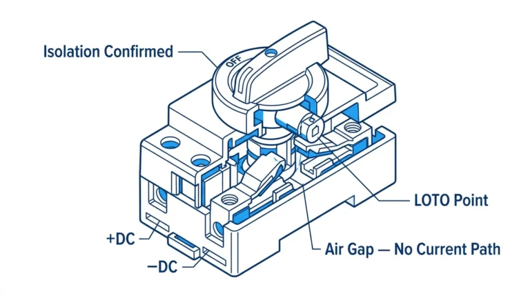
SPDs protect equipment by limiting voltage that reaches protected devices during surge events. Under normal conditions, SPDs present extremely high impedance offering minimal loading on circuits. When surge voltages exceed the SPD’s threshold voltage, the device transitions to low impedance, diverting surge current safely to ground before reaching protected equipment.
The key SPD performance parameter is clamping voltage—the maximum voltage appearing at protected equipment terminals during surge events. Lower clamping voltages provide better protection but require SPDs with tighter tolerances and more sophisticated protection elements. Clamping voltage must remain below equipment insulation levels while staying high enough above normal operating voltage to prevent false activation.
Metal oxide varistors (MOVs) form the basis of most solar DC SPDs, using voltage-dependent resistance that decreases dramatically during surges. Silicon avalanche diodes provide faster response than MOVs and tighter voltage clamping but handle less energy per device. Gas discharge tubes (GDTs) offer highest current handling but slower response, often used in hybrid SPD designs providing multiple protection stages.
💡 Key Insight: SPD protection isn’t a single device stopping all surges—effective solar protection uses coordinated SPD installations at multiple locations creating defense-in-depth. Each SPD handles surges appropriate to its location, with upstream devices managing high-energy threats and downstream devices providing fine protection.
IEC 61643-31 establishes standardized SPD classifications for photovoltaic systems, defining Type 1, Type 2, and Type 3 devices based on their tested current handling capabilities and intended installation locations. This classification system helps designers select appropriate SPDs for different positions within solar installations.
Type 1 SPDs undergo testing with 10/350μs current waveforms simulating direct lightning current pulses. These devices must handle extremely high energy content—test currents typically 25kA to 100kA per conductor. Type 1 designation indicates the SPD can withstand direct lightning strike energy, making these devices suitable for installation at service entrances and array origin points where direct strike energy might appear.
Type 2 SPDs test with 8/20μs waveforms representing induced surge currents from indirect lightning or switching transients. Test currents range from 10kA to 40kA—substantially lower than Type 1 but adequate for protecting against surges that have already passed through upstream protective elements. Type 2 devices install at equipment locations providing final protection stage before inverters and other sensitive electronics.
| Classification | Test Waveform | Typical Current | Primary Location |
|---|---|---|---|
| Type 1 | 10/350μs | 25-100kA | Service entrance, array origin |
| Type 2 | 8/20μs | 10-40kA | Equipment locations, inverter inputs |
| Type 3 | Combination wave | 1-10kA | Individual equipment, special applications |
Select SPD types based on installation location and expected threat levels rather than simply choosing the highest-rated devices. Type 1 SPDs cost significantly more than Type 2 devices and may not be necessary at all installation points. Understanding threat levels at different system locations allows optimized protection balancing cost and effectiveness.
Main DC combiners at array origins typically require Type 1 SPDs when arrays mount in exposed locations vulnerable to direct strikes. These points represent the first protection stage where maximum surge energy appears before any attenuation from conductors or other equipment. Type 1 devices at array origins protect downstream wiring and equipment from catastrophic direct-strike energy.
Inverter DC inputs generally use Type 2 SPDs providing final protection stage for sensitive electronics. By the time surge energy reaches inverters, upstream conductor impedance and Type 1 SPDs have reduced threat levels to ranges where Type 2 devices provide adequate protection. Installing Type 1 devices at every location wastes money without improving protection effectiveness.
⚠️ Important: Simply installing more SPDs doesn’t guarantee better protection—improper SPD selection or placement can actually worsen protection by creating ground loops, introducing noise, or causing protective coordination failures. Follow systematic design approaches balancing threat assessment, SPD capability, and installation economics.

Array combiners represent critical Type 1 SPD installation points, sitting at the intersection between exposed PV arrays and building electrical systems. Combiners collect multiple string circuits in single enclosures often mounted outdoors in exposed locations, making them vulnerable to both direct lightning attachment and induced surges from nearby strikes.
Install Type 1 SPDs in array combiners using three-pole (positive, negative, ground) configurations for ungrounded PV systems or two-pole (positive, ground) for solidly grounded negative systems. Each pole requires adequate current rating based on lightning exposure assessment—minimum 25kA per pole for moderate exposure locations, 50kA or higher for areas with high lightning activity.
Coordinate SPD installation with overcurrent protection, ensuring fuses or breakers protect SPD circuits without interfering with normal SPD operation during surges. Short circuit protection per NEC 690.35 requirements typically uses 15-20A fuses or breakers for SPD circuits. Some SPDs integrate thermal disconnectors that separate failed devices without external overcurrent protection.
Physical mounting location affects SPD effectiveness significantly. Mount SPDs with shortest possible lead lengths to equipment being protected—long wires between SPDs and equipment introduce inductance that degrades protection by allowing voltage overshoot during fast-rising surges. Ideally, SPD terminals should directly connect to protected equipment terminals without intervening conductors.
Main DC disconnects controlling entire array outputs provide another appropriate Type 1 SPD location. These points typically sit between array combiners and inverter equipment rooms, representing the building entrance point where NEC 690.35 specifically mandates surge protection when circuit conductors exceed certain lengths.
Type 1 SPDs at main disconnects provide redundant protection complementing array combiner SPDs, creating defense-in-depth. The two stages share lightning energy, with array SPDs handling most energy and main disconnect SPDs providing backup protection plus guarding against surges entering through the DC circuit from inverter or AC system directions.
In residential installations with short conductor runs, the main disconnect location may represent the only Type 1 SPD installation point, serving as both array protection and building entrance protection. Single-point protection proves adequate when conductor lengths remain short and lightning exposure moderate. High-exposure locations or systems with long conductor runs benefit from multiple Type 1 SPD installations.
Main disconnect SPD installations must account for higher continuous operating voltages at this location compared to string or combiner locations. Multiple strings in parallel reduce voltage ripple at combiner outputs, but the main disconnect sees the full array maximum power point voltage. Select SPDs with maximum continuous operating voltage (MCOV) ratings exceeding system MPP voltage to prevent premature SPD degradation.
Ground-mounted arrays in open fields face extreme lightning exposure, particularly in regions with high thunderstorm frequency. These installations benefit from Type 1 SPDs at array row combiners plus additional protection at the main array collection point. The distributed protection approach limits energy concentration at any single SPD, improving overall system survivability.
Consider lightning air terminals (traditional lightning rods) at ground array locations, especially for arrays extending above surrounding terrain. Properly designed air terminal systems with direct earth grounding intercept some lightning strikes before they attach to PV equipment. However, air terminals protect only through direct interception—they don’t eliminate induced surges from nearby strikes requiring SPD protection.
Conductor routing affects surge vulnerability in ground arrays. Route DC conductors in metallic conduit bonded to array grounding system, creating shielding that reduces electromagnetically induced surges. Where conduit isn’t feasible, bundle positive and negative conductors together minimizing loop area that couples with electromagnetic fields. Large conductor loops act as receiving antennas for surge energy.
Inverter DC inputs represent the most critical Type 2 SPD application point. Inverter electronics—especially maximum power point tracking circuits and DC-DC converters—feature low-voltage semiconductors extremely sensitive to overvoltage damage. Type 2 SPDs at inverter inputs provide the final protection stage guarding these vulnerable components.
Mount Type 2 SPDs directly at inverter DC terminals, not remotely in junction boxes or combiners feeding inverters. The goal is clamping voltage right at the equipment being protected, preventing any conductor length between SPD and inverter from introducing inductive voltage rise during fast surge currents. Many modern inverters incorporate integrated SPDs eliminating external SPD mounting requirements.
Select Type 2 SPD voltage ratings carefully—inverters operate at varying DC voltages from minimum MPPT voltage to open-circuit voltage depending on conditions. The SPD maximum continuous operating voltage (MCOV) must exceed maximum inverter input voltage under all conditions while providing clamping voltage low enough to protect inverter circuitry. This balance requires careful specification accounting for temperature-corrected maximum VOC.
Multiple inverters in large installations each require individual Type 2 SPD protection. Protecting inverters collectively with a single SPD at the main DC disconnect doesn’t provide adequate protection since conductor runs from that point to individual inverters introduce voltage rise negating SPD effectiveness. Budget for Type 2 SPDs at every inverter as essential protection components.
🎯 Pro Tip: Verify inverter warranty requirements regarding surge protection—many manufacturers void warranties if damage occurs and inadequate SPD protection is found. Document SPD installations with photos and specifications maintaining proof of proper protection throughout warranty periods.
While array combiners typically receive Type 1 SPDs as primary protection, supplemental Type 2 devices can provide additional safety margin in high-exposure installations. Type 2 SPDs at combiner outputs protect against surges that exceed Type 1 SPD capabilities or enter through unexpected paths. This redundant protection costs relatively little while significantly improving system reliability.
The Type 1/Type 2 combination at combiners requires proper coordination ensuring devices don’t fight each other during surge events. Maintain at least 10-15 meters of conductor between Type 1 and Type 2 SPDs allowing sufficient impedance for coordination, or use SPDs specifically designed for coordinated operation in close proximity. Improper coordination causes premature SPD failure and reduced protection effectiveness.
Combiner installations feeding multiple inverters benefit from Type 2 SPDs at the combiner output plus additional Type 2 SPDs at each inverter input. The combiner-level protection guards branch circuits, while inverter-level protection provides localized defense. This multi-stage approach mirrors best practices in commercial AC distribution systems where SPDs appear at multiple protection levels.
Monitoring systems, weather stations, and communication equipment connected to PV systems need surge protection matching the sensitivity of modern electronics. Type 2 SPDs designed for low-voltage data circuits protect these vulnerable components from surges coupling through monitoring cables. Ethernet, RS-485, and analog sensor circuits all require appropriate surge protection.
Communication circuit SPDs install at the interface between outdoor sensors/equipment and indoor monitoring systems. Cables running between arrays and monitoring rooms act as antennas collecting surge energy that enters monitoring electronics destroying network cards, data acquisition systems, and computers. Even small-energy surges that wouldn’t damage PV equipment can destroy sensitive communication electronics.
Coordinate SPD grounding with equipment grounding practices. All SPDs at a given location should reference the same ground point preventing ground potential differences from creating surge current flow through protected equipment. When remote equipment uses local grounding electrodes, install communication circuit SPDs at both ends of cables equalizing potential differences from lightning current flow through earth.

Effective SPD operation depends entirely on proper grounding—SPDs divert surge current to ground, making low-impedance ground connections critical for protection performance. Connect all SPD ground terminals directly to the main system grounding electrode using the shortest possible conductors. Long, coiled, or circuitous ground wires introduce impedance that degrades protection by allowing voltage rise during surge events.
NEC 690.35 requires SPD grounding conductors sized per NEC 250.166, typically 14 AWG copper minimum for Type 2 SPDs and 6 AWG minimum for Type 1 devices. However, meeting code minimum doesn’t guarantee optimal performance—consider 10 AWG for Type 2 and 4 AWG for Type 1 installations in high-exposure locations. The slightly higher cost proves worthwhile for improved surge current handling.
Bond SPD grounds to the same electrode system used for PV equipment grounding. Multiple separate grounds at different locations create ground potential rise differences during surge events, causing surge current to flow through equipment between ground points. A single common grounding system ensures all equipment and SPDs reference the same electrical potential eliminating inter-equipment surge currents.
Avoid sharp bends in SPD grounding conductors—bends introduce inductive impedance that increases voltage drop during fast-rising surge currents. Make gentle curves where routing requires direction changes. Some installations benefit from using flat copper strap rather than wire for SPD grounds, since strap exhibits lower inductance than round wire of equivalent cross-section.
⚠️ Important: Ground impedance matters more than ground resistance for SPD performance. A ground electrode with 25Ω resistance but short straight conductors provides better SPD performance than a 5Ω resistance electrode reached through 10 meters of coiled wire.
Lead length between SPDs and protected equipment critically affects protection performance. Every meter of conductor introduces roughly 1μH of inductance causing approximately 1kV voltage rise per meter during surge current di/dt of 1kA/μs—typical lightning surge rise times. This voltage rise adds to SPD clamping voltage, degrading protection or even allowing voltage sufficient to damage protected equipment despite SPD operation.
Install SPDs within 0.5 meters of protected equipment terminals whenever possible. This may require mounting SPDs inside equipment enclosures or on immediately adjacent junction boxes rather than remote wall-mounted locations. The inconvenience of close mounting proves worthwhile for significantly improved protection effectiveness.
Where separation between SPDs and equipment cannot be avoided, use twisted-pair routing for positive and negative SPD leads minimizing magnetic loop area. Twisting conductors reduces inductance by ensuring forward and return current paths occupy nearly the same space, causing their magnetic fields to largely cancel. Parallel conductors separated by even small distances create larger loop areas with proportionally higher inductance.
Some SPD manufacturers provide low-inductance connection terminals designed for flat copper bus bar or strap connections rather than traditional wire. These systems minimize parasitic inductance allowing SPD mounting slightly farther from protected equipment without excessive voltage rise. Consider these premium designs for critical installations where close SPD mounting proves difficult.
SPDs eventually fail from accumulated surge energy exposure or component aging, requiring replacement. Quality SPDs incorporate visual indication showing operational status—typically green LEDs or indicators showing SPD health and red indicators showing SPD failure requiring replacement. Check indicators during routine maintenance identifying failed SPDs before equipment damage occurs.
Thermal disconnection features automatically isolate failed SPDs preventing fire hazards from SPD component failures. Failed MOVs sometimes short-circuit rather than failing open, drawing excessive current that can cause enclosure fires. Thermal disconnectors sense elevated temperatures and mechanically separate failed SPD elements before fire ignition. NEC 690.35(B) requires disconnection features on SPDs in photovoltaic systems.
Install external overcurrent protection for SPDs when thermal disconnectors aren’t integrated in the device. Fuses typically 15-20A protect SPD circuits without interfering with surge current handling. The fuse rating must exceed maximum impulse current SPDs pass during coordination testing but provide reliable short-circuit protection if SPDs fail. Some jurisdictions require lockout/tagout-capable disconnecting means for SPD circuits allowing safe replacement.
Remote monitoring capabilities prove valuable in large or remote solar installations where frequent site visits aren’t practical. Advanced SPDs with network connectivity report their operational status to building management or monitoring systems, generating alerts when failures occur. This capability ensures rapid SPD replacement maintaining continuous protection rather than discovering failures during next scheduled maintenance visit.
NEC 690.35(A) mandates surge protective devices for DC circuits of solar photovoltaic systems when circuit conductors exceed specific distances from equipment being protected. The code aims to reduce lightning-induced surge damage by requiring protection where conductor runs create significant surge collection potential. Understanding these requirements ensures compliant installations avoiding inspection failures.
Systems with DC circuit conductors located more than 2 meters (6.6 feet) from PV array must have SPD protection per the 2020 NEC. This relatively short distance means virtually all solar installations except micro-inverter systems require DC SPDs—even residential arrays with inverters immediately below the array mounting point often exceed 2 meters due to conduit routing paths.
The SPD must be installed at the first readily accessible location on the DC circuit. For many installations this means array combiners or main DC disconnects at building entrances. Some systems install SPDs at inverter inputs when that represents the first accessible location, though best practice often includes additional SPDs at array locations providing multiple protection stages.
NEC doesn’t explicitly specify Type 1 versus Type 2 SPD requirements, instead referencing appropriate standards including UL 1449 and IEC 61643-31. However, 690.35(D) requires specific surge current ratings based on installation location and expected threats. Effectively, locations subject to direct lightning attachment need Type 1 capabilities while equipment locations can use Type 2 devices.
The code requires SPD ratings appropriate for the location and application but leaves specific ratings to the judgment of designers based on engineering analysis. This flexibility allows site-specific protection design but also places responsibility on designers to properly assess threats and specify adequate SPD ratings. Under-protection from inadequate SPD ratings won’t be caught by inspection until equipment damage occurs.
Authority Having Jurisdiction (AHJ) interpretations vary regarding specific SPD ratings required for code compliance. Some jurisdictions default to requiring Type 1 SPDs everywhere, while others accept properly engineered Type 2 applications at equipment locations. Discuss SPD design approach with local electrical inspectors early in design process avoiding costly change orders or installation delays from unexpected requirements.
NEC 690.35(C) requires SPDs to be listed for the application—typically UL 1449 listing for general SPDs or products evaluated under IEC 61643-31 for solar-specific devices. The listing requirement ensures SPDs undergo third-party testing verifying performance claims and safety characteristics. Field-fabricated surge suppressors or unlisted devices don’t satisfy code requirements regardless of their theoretical adequacy.
Proper labeling must identify SPD ratings including maximum continuous operating voltage (MCOV), voltage protection rating (VPR) or clamping voltage, and nominal discharge current rating (In) or maximum discharge current (Imax). Labels must remain permanently affixed and legible throughout SPD service life. Some jurisdictions require additional custom labels identifying SPDs as part of photovoltaic system surge protection.
SPD circuit overcurrent protection must be clearly labeled per 690.35(B)(2). When external fuses or breakers protect SPD circuits, label these protective devices identifying their function and proper replacement ratings. This prevents accidental replacement with incorrect overcurrent device ratings that might fail to protect SPDs or interfere with proper surge coordination.
Comprehensive solar system protection employs multiple SPD stages creating defense-in-depth. Primary protection typically consists of Type 1 SPDs at array origins handling high-energy direct strike currents. Secondary protection uses Type 2 SPDs at equipment locations providing fine clamping voltage for sensitive electronics. Each stage handles surges appropriate to its location with energy content progressively attenuated through the stages.
Proper coordination between stages requires adequate conductor impedance separation or deliberately coordinated SPD designs. When Type 1 and Type 2 SPDs install too close together, low conductor impedance between them can cause the lower-voltage Type 2 device to clamp first, forcing it to handle energy beyond its rating causing premature failure. Maintain at least 10-15 meters of conductor between stages or use SPDs specifically designed for close-proximity coordination.
Some manufacturers offer coordinated SPD systems where Type 1 and Type 2 devices are specifically designed to work together even in close proximity. These systems use SPDs with carefully selected clamping voltages and current-limiting characteristics ensuring the Type 1 device activates first and handles majority surge energy. Consider these premium systems when building layout makes stage separation difficult.
The energy handling progression moves from high-energy capable Type 1 devices to lower-energy but tighter-clamping Type 2 devices. Type 1 SPDs clamp at relatively higher voltages—800V to 1500V being typical—allowing them to handle massive energy without damage. Type 2 SPDs clamp lower—500V to 1000V—providing better equipment protection after Type 1 devices reduce surge energy to manageable levels.
SPD failure during surge events can leave equipment vulnerable unless backup protection exists. Redundant SPD installations at critical locations—particularly expensive inverters or complex monitoring systems—provide continued protection if primary SPDs fail. The relatively low cost of additional Type 2 SPDs at equipment locations often proves worthwhile compared to equipment replacement costs after unprotected surge exposure.
Overcurrent protection for SPD circuits provides backup protection by isolating failed SPDs. When SPDs fail short-circuit, the overcurrent device operates removing the failed device. However, this backup comes too late to protect against the surge causing SPD failure—equipment might already be damaged. Overcurrent protection prevents fire hazards and continuous faults but doesn’t replace properly rated initial SPD protection.
Consider supplemental protection elements like surge-rated fuses in string circuits providing additional protection specifically for PV modules. Standard gPV fuses protect against overcurrent conditions but surge-rated variants also provide limited overvoltage protection guarding modules against common-mode surges. This supplemental protection complements SPD protection rather than replacing it.
Problem: Installing SPDs rated only for AC service in DC solar applications without verifying DC capability.
Common scenarios:
– Assuming AC voltage ratings apply to DC systems
– Using standard building AC SPDs in PV installations
– Failing to verify DC ratings on SPD labeling
Correction: Specify SPDs explicitly rated for DC service at system voltage levels per IEC 61643-31 or UL 1449 DC ratings. AC and DC surge protection requirements differ significantly—AC SPDs lack the follow-current interrupting capability needed for DC service and may fail catastrophically. Verify every SPD installed carries appropriate DC voltage and current ratings for the specific application.
Problem: Installing SPDs remotely from protected equipment with long connecting conductors.
Common scenarios:
– Wall-mounting SPDs meters away from inverters for neat appearance
– Installing SPDs in junction boxes rather than directly at equipment terminals
– Routing SPD leads through complex conduit paths instead of straight connections
Correction: Mount SPDs within 0.5 meters of protected equipment using shortest possible lead lengths. Every meter of conductor adds inductive voltage rise during surges degrading protection effectiveness. Prioritize protection performance over installation aesthetics—accepting slightly messier installations with close-mounted SPDs proves worthwhile for significantly improved equipment protection.
Problem: SPD ground connections using inadequate conductor sizes, excessive lengths, or multiple separate ground electrodes.
Common scenarios:
– Using minimum code wire sizes instead of optimal larger conductors
– Creating circuitous ground paths rather than shortest direct routes
– Grounding different SPDs to separate electrodes creating ground loops
Correction: Use 10 AWG minimum for Type 2 SPDs and 4 AWG for Type 1 devices with straight direct runs to common grounding electrode system. Bond all SPDs and equipment to single electrode system preventing ground potential differences that cause inter-equipment surge currents. Consider flat copper strap for premium installations reducing inductive impedance below round wire.
Problem: Installing SPDs without status indication features or never checking operational condition.
Common scenarios:
– Assuming SPDs provide continuous protection throughout system lifetime
– No routine inspection of SPD status indicators
– Failed SPDs remaining in systems for years without replacement
Correction: Specify SPDs with visual status indication showing operational condition. Include SPD inspection in routine maintenance procedures—check indicators quarterly in high-exposure locations or annually in moderate areas. Replace failed SPDs immediately rather than deferring—operating without surge protection invites expensive equipment damage during next lightning season. Consider remote monitoring SPDs for critical or inaccessible installations.
Floating (ungrounded) PV systems where no conductor connects intentionally to ground face different SPD requirements than grounded systems. Floating systems need three-pole SPDs protecting positive, negative, and ground references simultaneously. Grounded systems might use two-pole protection when negative conductor connects solidly to ground, though three-pole designs provide more robust protection.
The SPD maximum continuous operating voltage (MCOV) rating must account for system grounding configuration. Floating systems develop voltage equally on both positive and negative conductors relative to ground—for a 600V DC system, each conductor might reach ±300V relative to ground. SPDs for each conductor need MCOV ratings appropriate for this voltage, potentially allowing use of lower-voltage devices than required for grounded systems where full voltage appears on the ungrounded conductor.
Ground fault detection interacts with SPD installation in both grounded and floating systems. SPDs create intentional conductive paths to ground when operating, potentially causing ground fault detection systems to trip during surge events. Select GFD systems compatible with SPD presence, using detection thresholds above SPD leakage currents but low enough to detect dangerous ground faults.
Solar systems operating above 1000V DC—increasingly common in utility-scale installations—require specialized SPDs designed for extreme voltage levels. Component availability becomes constrained at these voltages with fewer manufacturers offering suitable products. Early SPD specification and procurement proves critical avoiding project delays from long lead times or limited vendor options.
High-voltage SPD installations require enhanced safety precautions including greater creepage and clearance distances, enclosed SPD modules preventing accidental contact, and comprehensive warning labels. Personnel working on high-voltage systems need specialized training beyond standard electrical qualifications. Document SPD installations thoroughly including wiring diagrams and maintenance procedures specific to high-voltage equipment.
Consider hybrid SPD technologies for high-voltage applications. Gas discharge tubes paired with metal oxide varistors provide high voltage capability of GDTs with tight voltage clamping of MOVs. Silicon avalanche diodes offer ultra-fast response protecting sensitive high-voltage electronics but require series-parallel arrangements to handle sustained power. Consult surge protection specialists for high-voltage system designs rather than extrapolating from lower-voltage experience.
Regions with exceptionally high lightning ground flash density—above 10 flashes per square kilometer annually—may require enhanced protection beyond minimum code requirements. Utility-scale arrays in Florida, the Gulf Coast, or mountainous areas face extreme lightning exposure demanding robust protection design with generous safety margins.
Consider external lightning protection systems with air terminals and down conductors separate from PV electrical systems in extreme exposure locations. Proper lightning protection system (LPS) design per NFPA 780 or IEC 62305 intercepts some strikes before attachment to PV equipment, though SPDs remain necessary for induced surge protection. The LPS and SPD systems work together providing comprehensive protection addressing both direct strikes and induced transients.
Remote monitoring and rapid SPD replacement protocols prove especially important in high-exposure regions. Budget for annual SPD replacement even without observed failures—the cumulative stress from numerous sub-threshold surge events gradually degrades SPD performance until catastrophic failure occurs. Proactive replacement based on exposure rather than waiting for failures maintains optimal protection preventing expensive equipment damage.

Type 1 SPDs handle direct lightning strike energy tested with 10/350μs waveforms at 25-100kA, making them suitable for array origins and service entrances. Type 2 SPDs protect against induced surges and attenuated lightning tested with 8/20μs waveforms at 10-40kA, appropriate for equipment locations after upstream protection. Type 1 devices install where maximum surge energy appears, while Type 2 devices provide final protection stage for sensitive electronics after surge energy has been partially attenuated by conductors and upstream SPDs.
Install Type 1 SPDs at array combiners or string boxes where conductors originate from exposed PV arrays, and at main DC disconnects at building entrances. These locations face highest surge energy exposure from direct or nearby lightning strikes. Install Type 2 SPDs at inverter DC input terminals providing final protection for sensitive power electronics. Large systems benefit from Type 1 at combiners and main disconnect plus Type 2 at each inverter creating three-stage coordinated protection.
Yes, DC and AC surge protection address different threats in different system sections. DC SPDs protect PV arrays, string wiring, combiners, and inverter DC inputs from surges entering through the DC circuit—AC SPDs can’t protect these components. Lightning strikes to arrays or nearby strikes inducing surges in DC conductors require DC SPDs for protection. AC SPDs protect the inverter AC output and building electrical system from surges entering through grid connections, serving completely different protective function than DC SPDs.
Quality SPDs incorporate visual indicators showing operational status—typically green showing normal operation and red indicating failure requiring replacement. Check indicators quarterly in high-exposure locations or annually elsewhere. Some SPDs include remote monitoring contacts reporting status to building management systems. Replace any SPD showing failure indication immediately. In extreme lightning exposure regions, consider proactive replacement every 5-7 years regardless of indicator status since cumulative sub-threshold surge exposure gradually degrades performance even without obvious failures.
No, SPD voltage ratings must match or exceed maximum system open-circuit voltage including temperature correction. A 600V system might require SPDs rated 800V DC while 1000V systems need 1200-1500V DC ratings. Using under-rated SPDs causes premature failure or allows excessive voltage reaching protected equipment. The SPD maximum continuous operating voltage (MCOV) must exceed system maximum power point voltage, while voltage protection rating must stay below equipment insulation levels. Always specify SPDs explicitly for your system voltage with adequate safety margin.
Type 2 SPDs at inverters might fail when exposed to high-energy surges normally handled by upstream Type 1 devices. Lightning strikes or nearby strikes can inject energy levels exceeding Type 2 ratings causing catastrophic SPD failure and allowing full surge energy to reach inverters. Even if Type 2 SPDs survive initial surge, the stress gradually degrades them requiring frequent replacement. Proper protection uses appropriate SPD types at each location—Type 1 where high energy appears and Type 2 for final equipment protection after energy attenuation.
SPD ground conductors should be as short as possible—ideally under 1 meter—connecting directly to the main grounding electrode system. Every meter of ground conductor introduces roughly 1μH inductance causing approximately 1kV voltage rise during fast surge currents. This voltage rise adds to SPD clamping voltage potentially allowing damaging voltages despite SPD operation. Use straight direct ground paths avoiding coils or unnecessary bends. In premium installations consider flat copper strap rather than round wire for lower inductance. Bond all SPDs and equipment to single common grounding electrode preventing ground loop currents.
Comprehensive solar surge protection requires understanding how SPDs integrate with other protective components and grounding systems.
Learn more about related surge protection topics in our detailed guides:
– DC Surge Protection System Design – Complete SPD specification and coordination
– Solar Lightning Protection – External lightning protection system integration
– PV Combiner Box Protection – SPD installation in combiner assemblies
– DC Grounding Requirements – Proper grounding electrode systems for SPD effectiveness
Ready to implement effective DC SPD protection for your solar installation? Our technical team at SYNODE provides project-specific SPD selection guidance including Type 1 versus Type 2 determination, coordination analysis, and proper installation design. We help ensure comprehensive surge protection meeting NEC 690.35 requirements while optimizing protection economics for projects from residential to utility-scale.
Contact our application engineers for SPD specification assistance and lightning protection system design services.
Last Updated: October 2025
Author: SYNODE Technical Team
Reviewed by: Electrical Engineering Department