Address
304 North Cardinal
St. Dorchester Center, MA 02124
Work Hours
Monday to Friday: 7AM - 7PM
Weekend: 10AM - 5PM
Address
304 North Cardinal
St. Dorchester Center, MA 02124
Work Hours
Monday to Friday: 7AM - 7PM
Weekend: 10AM - 5PM

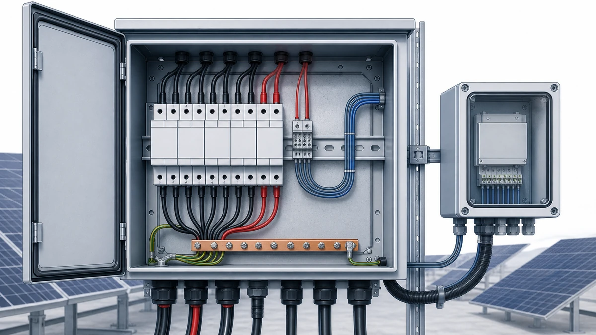
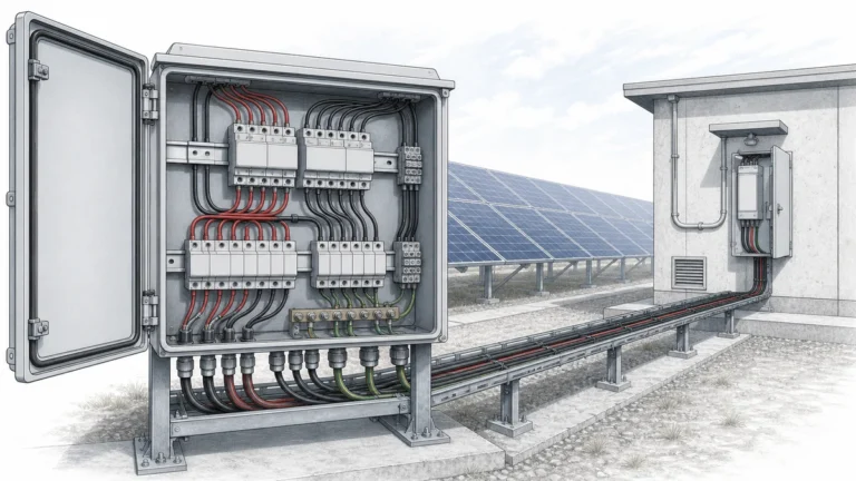
For large solar portfolios, surge protection is not only an electrical design topic. It is also a maintenance visibility topic. A failed or end-of-life DC surge protective device can leave strings, combiner boxes, inverter DC inputs, or auxiliary DC circuits exposed until the next inspection. That gap becomes larger when assets are spread across rooftops, ground-mount plants, and remote sites.
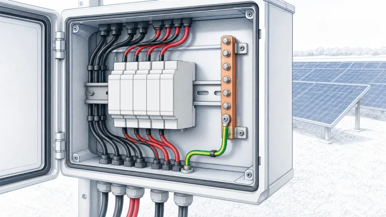
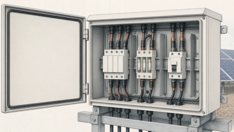
This is where **dc spd remote signalling** becomes valuable. A DC SPD with remote signalling contacts can send a status change to a monitoring system, data logger, inverter alarm input, SCADA panel, or site controller when the device reaches a fault or replacement condition. For Sinobreaker DC SPD applications, the contact should be treated as part of the complete PV protection and maintenance arrangement, not as a generic alarm accessory.
IEC 61643-32 covers selection, installation, and coordination principles for SPDs in photovoltaic systems up to 1,500 V DC. That matters because remote indication should follow the actual SPD role, PV voltage level, installation point, backup protection, and inspection workflow—not just the availability of a pair of signal terminals.
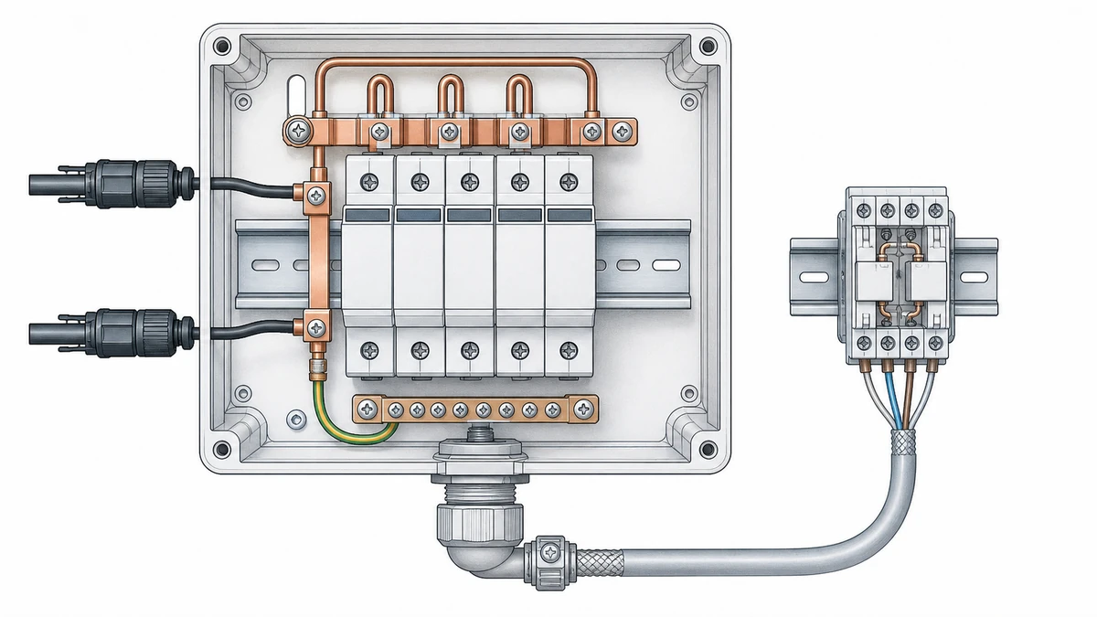
PV sites often have hundreds or thousands of DC protection points. Manual inspection alone can miss the moment when an SPD changes state after repeated surge exposure or a major transient event. A remote alarm contact helps maintenance teams identify where attention is needed before the next scheduled visit.
A remote signalling contact is normally used to report whether the SPD is still in its normal operating state or has entered a fault/replacement state. In a solar portfolio, this signal can be routed to:
The purpose is not to measure surge energy directly. The purpose is to make the SPD replacement condition visible to operators.
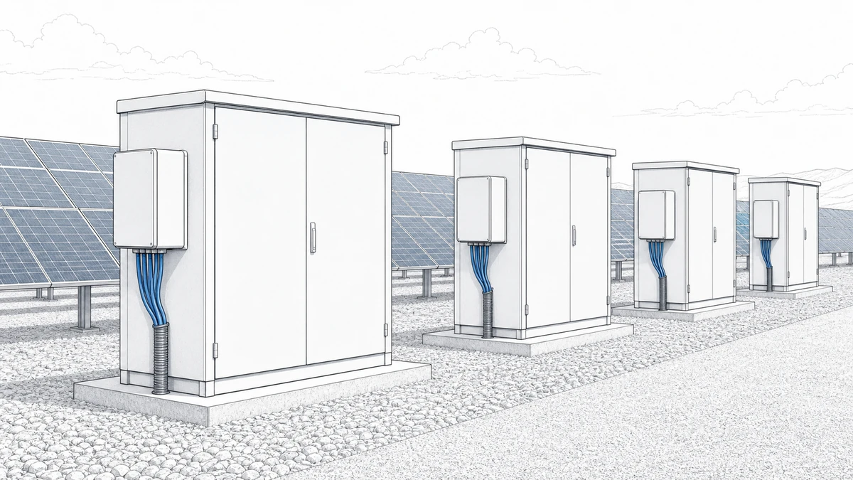
Distributed PV portfolios often include sites with different enclosure designs, inverter models, commissioning dates, and maintenance schedules. Without remote indication, the condition of DC SPDs may depend on a technician physically opening each enclosure and checking the visual indicator.
Remote signalling reduces this blind spot by allowing the monitoring system to flag an affected location. The local visual indicator still remains important for confirmation during inspection, but the remote alarm improves response time.
PV surge protection manufacturers commonly combine visual status indication with optional remote signalling. This split is practical: the visual indicator supports field inspection, while the remote contact supports centralized monitoring.
For Sinobreaker DC SPD maintenance planning, both should be used correctly. The monitoring alarm tells the operator where to look. The local indicator helps the technician verify the actual device condition at the enclosure.
A remote signalling contact is an auxiliary contact mechanically or electrically linked to the SPD’s status mechanism. When the SPD reaches its defined fault or end-of-life state, the contact changes state and allows an external circuit to detect the condition.
Many remote signalling designs use a changeover contact. Depending on the device, the terminals may provide common, normally open, and normally closed contact points. This allows the alarm designer to choose either fail-open or fail-closed monitoring logic.
For PV portfolios, fail-safe thinking is important. If a cable breaks, a terminal loosens, or an input loses power, the monitoring system should ideally detect an abnormal condition rather than silently showing “OK.” The best logic depends on the selected Sinobreaker DC SPD model, the input module, and the site alarm philosophy.
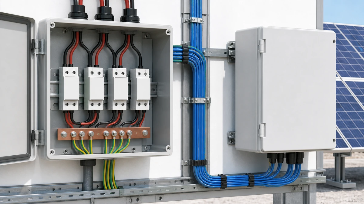
A common mistake is to assume every remote signalling output can accept any alarm voltage or current. In practice, published data sheets for PV SPDs often specify contact-voltage and contact-current limits, and some also publish backup-fuse requirements.
Therefore, an alarm-input design must follow the selected Sinobreaker DC SPD data sheet. The signal circuit should not be copied from another SPD brand, another voltage class, or an AC protection product without checking the ratings.
Key items to confirm include:
A remote OK/fault indication does not show the accumulated surge stress inside the arrester. It also does not accurately predict remaining service life. It is a status signal, not a condition-monitoring measurement.
This distinction is important for O&M teams. A healthy remote indication means the SPD has not reached its defined fault state. It does not mean the device has experienced no surge activity, and it does not replace periodic inspection, thermal checks, enclosure checks, or review after major lightning events.
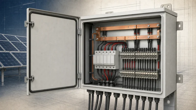
Remote signalling should be designed at the same time as the DC SPD arrangement, cable routing, enclosure layout, monitoring architecture, and maintenance workflow. It should not be added at the end as a spare alarm input.
The remote contact and monitoring input must be electrically compatible. A low-voltage digital input on a data logger may use 12 V DC or 24 V DC, while a PLC input may have different thresholds. Some inverter alarm inputs use wet contacts, while others expect dry-contact closure.
Before wiring a Sinobreaker DC SPD remote contact, confirm:
The SPD contact should switch only within its permitted electrical limits.
Remote signalling conductors are low-energy control wires. They should not be routed as if they were DC string conductors. Poor routing can introduce noise, unwanted coupling, or mechanical damage risk.
Good practice includes keeping signal cables away from high-current DC paths where possible, using suitable insulation ratings, maintaining enclosure segregation, and following the site’s earthing and bonding plan. Where long signal runs are unavoidable, the alarm circuit may need additional protection or isolation according to the monitoring-system design.
IEC 61643-32 emphasizes that SPD selection, installation, and coordination in PV systems must be handled as a complete protection arrangement. Remote indication does not change the need to verify the SPD’s electrical suitability.
For each Sinobreaker DC SPD installation point, confirm:
A remote alarm cannot compensate for an incorrectly selected DC SPD.
A remote alarm should trigger a defined maintenance process. Without a process, the alarm may be acknowledged and forgotten, leaving the PV system operating with reduced surge protection.
The monitoring platform should identify the device location clearly. Useful alarm labels include site name, inverter block, combiner-box number, string group, enclosure ID, and SPD position. A vague alarm such as “SPD fault” is less useful when the portfolio includes many devices.
Recommended alarm data includes:
This helps the O&M team decide whether the response is urgent or can be grouped with a planned visit.
When a technician arrives on site, the remote signal should be verified against the SPD’s local status indication and the enclosure condition. The technician should follow safe isolation procedures for PV DC circuits before touching or replacing any device.
Local checks may include:
If the local visual indicator and remote alarm disagree, the signal wiring, monitoring input, and contact logic should be checked.
After replacing a failed SPD or module, the alarm should return to the normal state. The maintenance record should capture the installed part, date, site location, suspected cause, technician notes, and any related lightning or grid disturbance events.
This record improves future stocking and portfolio planning. If one site shows repeated SPD replacements, the issue may point to a higher lightning exposure area, grounding concern, wiring issue, or coordination problem.
Remote signalling is simple in principle, but small design errors can reduce reliability or create misleading alarms.
Different DC SPD models may have different remote-contact ratings. Some contacts are suitable for low-voltage control circuits only. Others may publish specific AC and DC switching limits. The selected Sinobreaker data sheet should be the controlling document.
A remote OK status does not show how much surge energy the SPD has absorbed. It only confirms that the device has not reached its defined fault state. Portfolio operators should keep periodic inspection and event-based checks in the maintenance plan.
If alarm labels are inconsistent, the monitoring system may show a fault without telling the operator which enclosure contains the affected SPD. A standard naming scheme should be created before commissioning.
Monitoring does not replace electrical verification. The DC SPD still needs the correct PV voltage rating, discharge capacity, short-circuit suitability, and backup protection arrangement for the installation point.
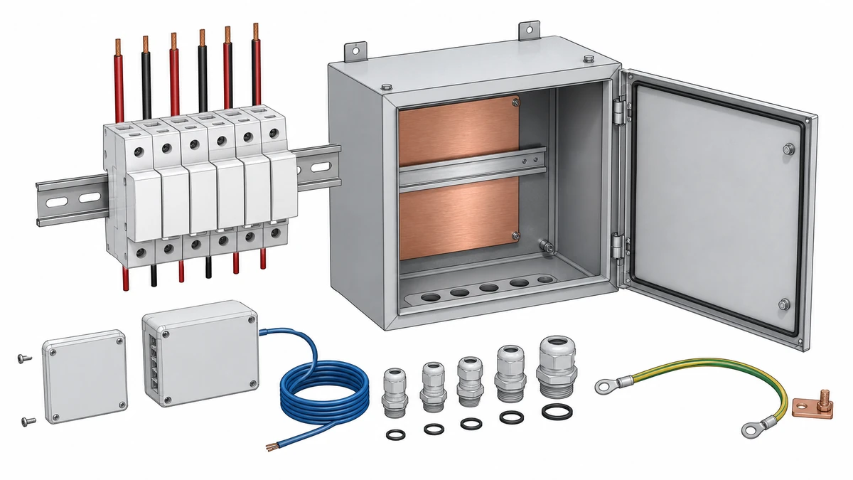
Sinobreaker DC SPD remote signalling should be specified with both the electrical protection function and the maintenance workflow in mind. The best result comes from aligning the SPD data sheet, enclosure layout, monitoring input, and O&M response process before installation.
When writing a project specification for **dc spd remote signalling**, include:
This keeps procurement, installation, commissioning, and maintenance aligned.
During commissioning, installers should verify both the surge protection function and the alarm function. The remote signal should not be assumed correct just because the SPD is physically installed.
Commissioning checks should include:
A tested alarm is far more valuable than an unused auxiliary contact.
DC SPD remote signalling is the use of an auxiliary status contact on a DC surge protective device to send an OK or fault/replacement signal to a monitoring system. In solar applications, it helps operators identify which PV protection point needs inspection after the SPD reaches its defined fault state.
No. Remote signalling improves visibility, but it does not replace local inspection. The SPD’s visual indicator, enclosure condition, wiring, backup protection, and installation environment should still be checked during scheduled maintenance or after significant surge events.
Not safely. Remote contact ratings and terminal logic can vary by product. The alarm circuit must follow the selected Sinobreaker DC SPD data sheet, including voltage limits, current limits, contact type, wiring method, and any required signal-circuit protection.