Dirección
304 North Cardinal
Dorchester Center, MA 02124
Horas de trabajo
De lunes a viernes: de 7.00 a 19.00 horas
Fin de semana: 10.00 A 17.00 HORAS
Dirección
304 North Cardinal
Dorchester Center, MA 02124
Horas de trabajo
De lunes a viernes: de 7.00 a 19.00 horas
Fin de semana: 10.00 A 17.00 HORAS


Surge protection for solar systems is not optional—it’s mandatory under NEC 690.35 and essential for protecting expensive inverters, charge controllers, and monitoring equipment from voltage transients that occur daily in photovoltaic installations.
Every solar system experiences voltage surges from multiple sources: lightning strikes within several kilometers, utility switching operations, and internal system events like inverter startup. Without proper surge protection devices (SPDs), these transients gradually degrade equipment or cause catastrophic failure.
This guide provides comprehensive SPD selection matrices that help you choose the right protection type, voltage rating, and coordination strategy for any solar installation. We’ll analyze Type 1, Type 2, and Type 3 SPDs across residential, commercial, and utility-scale systems with clear decision criteria based on system configuration, risk level, and code requirements.
💡 Información clave: The right SPD specification isn’t about maximum protection—it’s about matching protection level to threat probability while optimizing cost-effectiveness. A $200 Type 2 SPD protects most residential systems adequately, while $2,000 coordinated Type 1+2 protection is essential for high-value commercial installations.
Surge protection for solar systems consists of specialized devices installed in the DC and AC electrical pathways that detect voltage surges and divert excess energy to ground before it reaches sensitive equipment like inverters and battery systems.
Dispositivo de protección contra sobretensiones (SPD): An electronic component containing metal oxide varistors (MOVs) or gas discharge tubes (GDTs) that rapidly change from high impedance to low impedance when voltage exceeds safe levels, creating a low-resistance path to ground.
Protection Level (Up): The maximum voltage that appears across the SPD during a surge event—this is the voltage your equipment must withstand. Lower protection levels provide better equipment safety.
Discharge Current Rating (In, Imax): The amount of surge current the SPD can safely divert to ground. Higher ratings protect against larger surges but cost more and occupy more space.
Solar surge protection operates automatically in microseconds without human intervention. When a voltage surge occurs—whether from lightning, utility switching, or internal system events—the SPD detects the overvoltage and instantly creates a shunt path to ground.
Three Protection Functions:
1. Voltage Clamping: SPDs limit voltage to safe levels (typically 1.2-2.5× normal operating voltage) by diverting surge current
2. Energy Absorption: MOV elements absorb surge energy as heat, protecting downstream equipment
3. Self-Sacrifice: SPDs degrade with each surge event, eventually failing open-circuit or short-circuit (with disconnector) to prevent equipment damage
Analogía del mundo real: Think of SPDs as pressure relief valves on a boiler. Normally they’re invisible and inactive, but when pressure (voltage) exceeds safe limits, they automatically open to release excess energy. Like relief valves, they sacrifice themselves to protect more valuable equipment.
Alternating current naturally crosses zero voltage 120 times per second, helping extinguish electrical arcs. Direct current from solar panels maintains constant polarity, making arc extinction far more difficult once initiated.
Ejemplo real: An AC-rated SPD used incorrectly on a 600V DC solar string may extinguish surges initially but fail catastrophically during a major event when the DC arc doesn’t self-extinguish, potentially causing fire.
Modern solar systems operate at 600V, 1000V, or 1500V DC—far exceeding residential AC voltages. These elevated voltages mean surges can reach 2000-4000V, requiring SPDs rated for the higher voltage stress.
NEC 690.35 Recognition: The code specifically requires DC-rated SPDs because standard AC protection devices cannot safely operate in high-voltage DC applications.
Solar DC wiring extends 50-300 feet in residential systems and over 1000 feet in commercial installations. These long conductors act as antennas picking up electromagnetic pulses from nearby lightning strikes even kilometers away.
SPDs at both ends of long cable runs (array and inverter) prevent induced voltages from damaging either end of the system.
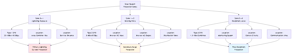
Solar systems face surge threats from multiple directions simultaneously: DC side surges from array exposure, AC side surges from utility grid, and communication line surges through monitoring systems. Each pathway needs appropriate SPD protection rated for its specific voltage and current characteristics.
Modern string inverters cost $1,500-$8,000 and contain sensitive microprocessors vulnerable to voltage transients. Battery inverters and energy storage systems add $5,000-$20,000 of surge-vulnerable equipment. The cost of comprehensive SPD protection ($500-$3,000) is trivial compared to single equipment replacement.
Understanding SPD types is essential for proper selection. The classification determines where devices should be installed and what level of protection they provide.
Primary Characteristics:
Type 1 SPDs handle direct lightning current with discharge capacities of 25kA to 100kA (10/350μs waveform). They install between overhead lines and the main distribution panel, designed for the first point of building protection.
Construcción: Heavy-duty components including spark gaps or gas discharge tubes combined with MOVs. Large physical size (often 6+ inches tall) to accommodate high energy absorption requirements.
Voltage Protection Level: Typically 1.5-2.5kV for 230V AC systems, 2.5-4.0kV for 600V DC systems.
Installation Location: Service entrance panel, main distribution board, or solar array combiner boxes in direct lightning exposure zones.
Cost Range: $200-$800 per device depending on discharge current rating and number of protection elements.
✅ When Required:
– Ground-mounted solar arrays exposed to direct strikes
– Service entrance protection per NEC 230.67 (optional but recommended)
– High lightning-risk areas (>25 strikes/km²/year)
– Systems with overhead AC or DC service conductors
❌ Not Necessary When:
– Rooftop arrays on buildings with existing building-level lightning protection
– Low lightning-risk urban areas with underground service
– Small residential systems under 10kW in standard-risk zones
Primary Characteristics:
Type 2 SPDs protect against conducted surges with discharge capacities of 8kA to 40kA (8/20μs waveform). They install at distribution boards and critical equipment locations like inverters.
Construcción: Metal oxide varistor (MOV) technology in compact housings. Multiple MOV discs in series/parallel provide desired voltage and current ratings.
Voltage Protection Level: Typically 1.2-2.0kV for 230V AC systems, 1.8-3.0kV for 600V DC systems (lower than Type 1).
Installation Location: Inverter DC input terminals, inverter AC output, sub-distribution panels, critical load panels.
Cost Range: $80-$400 per device depending on voltage rating and number of poles.
✅ Standard Applications:
– Residential rooftop solar systems (NEC 690.35 minimum requirement)
– Inverter DC input protection
– Inverter AC output protection
– Battery system DC protection
🎯 Consejo profesional: Type 2 SPDs should be installed as close as possible to protected equipment—ideally within 30cm (12 inches)—to minimize voltage overshoot from lead inductance. Longer connection leads reduce SPD effectiveness significantly.
Primary Characteristics:
Type 3 SPDs provide final protection for sensitive electronics with discharge capacities of 1.5kA to 10kA (combination wave). They install directly at equipment terminals or within devices.
Construcción: Small MOV components or transient voltage suppressors (TVS) diodes optimized for fast response time (<25 nanoseconds) rather than high current capacity.Voltage Protection Level: Typically 0.8-1.5kV for 230V AC systems, 1.2-2.0kV for DC circuits (lowest clamping voltage).
Installation Location: Monitoring equipment, communication lines, control circuits, individual load connections.
Cost Range: $30-$150 per device for small current ratings.
✅ Specialized Uses:
– RS485 communication line protection for monitoring systems
– Ethernet/WiFi communication protection for inverter monitoring
– Sensor and control circuit protection
– High-sensitivity equipment protection after Type 1+2 coordination
❌ Cannot Replace: Type 3 SPDs lack energy capacity to serve as primary surge protection and must always be used in conjunction with Type 1 or Type 2 devices.
| Parámetro | Low Risk Ng <10 | Moderate Risk Ng 10-25 | High Risk Ng >25 |
|---|---|---|---|
| DC Side Protection | Tipo 2 20kA (8/20µs) | Tipo 2 40kA (8/20µs) | Type 1+2 50kA (10/350µs) |
| AC Side Protection | Tipo 2 20kA single-phase | Tipo 2 40kA single-phase | Tipo 2 65kA single-phase |
| Communication Protection | Tipo 3 If monitoring used | Tipo 3 Recommended | Tipo 3 Required |
| Installation Points | 1-2 locations | 2-3 locations | 3-4 locations |
| Total Protection Cost | $200-$500 | $500-$1,200 | $1,200-$2,500 |
Configuration Details:
Low-Risk Systems:
– Single Type 2 SPD at inverter DC input (often integrated in quality inverters)
– Optional Type 2 SPD at main AC panel
– Minimal communication protection unless high-value monitoring
Moderate-Risk Systems:
– Type 2 SPD at inverter DC input (40kA rating)
– Type 2 SPD at inverter AC output
– Type 3 SPD on RS485 or Ethernet monitoring lines
– Enhanced grounding with <10Ω resistanceHigh-Risk Systems:
– Type 1 or Type 1+2 combined SPD at array combiner if ground-mount
– Type 2 SPD at inverter DC input (coordinated with Type 1)
– Type 2 SPD at inverter AC output and main panel
– Type 3 SPD on all communication circuits
| Protection Element | Minimum Specification | Recommended Specification | Premium Specification |
|---|---|---|---|
| DC Combiner SPD | Type 2, 40kA per IEC 61643-11 | Type 1+2, 50kA 12.5kA Iimp | Type 1, 100kA 25kA Iimp |
| Entrada CC del inversor | Type 2, 20kA per string | Type 2, 40kA coordinated | Type 2, 65kA with remote indicator |
| AC Distribution | Type 2, 40kA 3-phase | Type 2, 65kA 3-phase + neutral | Type 1, 100kA full coordination |
| Communication/Data | Basic Type 3 data lines only | Type 3 all circuits with shielding | Coordinated Type 2+3 full monitoring |
| Monitoring Features | Visual indicators only | Remote alarm contacts | SCADA integration predictive alerts |
| System Cost | $1,500-$3,000 | $3,000-$6,000 | $6,000-$12,000 |
Selection Guidelines:
Elija Minimum specification for:
– Standard-risk zones (Ng 10-20)
– Rooftop arrays on buildings with existing lightning protection
– Budget-constrained projects with basic insurance requirements
Elija Recommended specification for:
– Most commercial installations (industry standard)
– Moderate-to-high risk zones (Ng 20-30)
– Systems requiring insurance compliance documentation
Elija Premium specification for:
– High-value critical facilities
– High lightning-risk zones (Ng >30)
– Systems with extended warranties requiring comprehensive protection
– Facilities requiring maximum uptime (hospitals, data centers)

Maximum Continuous Operating Voltage (MCOV/Uc):
This is the highest continuous DC voltage the SPD can withstand without conducting. Choose MCOV at least 1.15× system Voc (open-circuit voltage) to prevent nuisance triggering from cold-weather voltage rise.
Selection Formula:
MCOV ≥ (Voc × 1.15) + safety margin
Ejemplo de cálculo:
– System: 16 panels × 42V Voc = 672V string voltage
– Minimum MCOV: 672V × 1.15 = 773V
– Selected SPD: MCOV = 800V or 1000V standard rating
– Never use: 600V MCOV SPD (would fail from normal operation)
⚠️ Advertencia: Using an SPD with insufficient MCOV causes premature failure. The device conducts during normal high-voltage conditions (cold mornings), rapidly degrading the MOV elements and failing open or short-circuit.
Voltage Protection Level (Up):
This specifies the maximum voltage that appears across the SPD terminals during surge events. Lower is better for equipment protection.
Typical Values by Type:
– Type 1 DC SPDs: Up = 2.5-4.0kV (1000V systems)
– Type 2 DC SPDs: Up = 1.8-3.0kV (1000V systems)
– Type 3 DC SPDs: Up = 1.2-2.0kV (1000V systems)
Equipment Compatibility Check:
Verify that inverter surge immunity rating exceeds SPD protection level. Most modern inverters withstand 4-6kV surge immunity, providing adequate margin with Type 2 SPDs (Up ≈ 2.5kV).
Nominal Discharge Current (In):
The current rating used for classification and testing. Type 2 SPDs typically rated 20kA, 40kA, or 65kA (8/20μs waveform).
Selection by Risk Level:
- Low risk (Ng <10): 20kA sufficient for rooftop arrays
- Moderate risk (Ng 10-25): 40kA recommended
- High risk (Ng >25): 65kA or Type 1 (100kA) required
Maximum Discharge Current (Imax):
The highest surge current the SPD can handle without failure. Typically 1.5-2× the nominal rating.
For Type 1 SPDs, the critical specification is Iimp (impulse current) using 10/350μs waveform, measuring direct lightning strike capacity. Minimum 12.5kA Iimp for exposed arrays, 25kA for high-risk installations.
Response Time (<25ns for MOV-based SPDs):
How quickly the SPD begins conducting after surge voltage appears. Fast response (<50ns) is critical for protecting sensitive inverter electronics.
MOV technology provides fastest response. Gas discharge tubes (GDTs) have slower response (100ns-1μs) but higher energy capacity—often used in combination with MOVs for Type 1 applications.
Let-Through Current:
The amount of surge current that passes through the SPD to protected equipment. Quality SPDs limit let-through to <1% of surge current through proper impedance matching.
Enclosure Rating:
- Indoor inverters: IP20 minimum (NEMA 1)
- Outdoor combiner boxes: IP65 minimum (NEMA 3R)
- Harsh environments: IP66/IP67 (NEMA 4X)
Gama de temperaturas:
Standard SPDs operate -40°C to +85°C. Verify operating range matches installation environment—attic-mounted inverters may exceed 70°C ambient.
Altitude Derating:
SPDs lose effectiveness at high altitude due to reduced air dielectric strength. Apply 1% voltage derating per 100m elevation above 1000m.
Installing multiple SPDs at different locations creates a protection cascade. Without proper coordination, SPDs interact destructively rather than cooperatively, potentially allowing one device to fail while others don’t activate.
Three Coordination Factors:
1. Energy Sharing: Properly coordinated SPDs share surge energy proportionally based on impedance and distance
2. Voltage Signature: Each SPD must clamp at appropriate voltage to ensure cascade activation
3. Installation Distance: Minimum separation required between SPD types for proper operation
When using both Type 1 and Type 2 SPDs in the same system, maintain minimum separation distance for inductive decoupling.
Minimum Separation Requirements:
- >10 meters cable length: No additional coordination needed
- 5-10 meters: Use series impedance (inductor/resistor)
- <5 meters: Use coordinated SPD sets from same manufacturer
Example Configuration:
– Type 1 SPD at array combiner box (exposed to direct strikes)
– 15 meters of cable run to inverter
– Type 2 SPD at inverter DC input
– Result: Proper separation allows Type 1 to handle primary surge while Type 2 provides equipment-level clamping
Fine protection for sensitive monitoring and control equipment requires Type 2 upstream and Type 3 at device terminals.
Typical Application:
– Type 2 SPD at main inverter DC terminals (40kA capacity)
– Type 3 SPD at inverter communication board (5kA capacity)
– Separation: 2-3 meters internal inverter wiring provides adequate decoupling
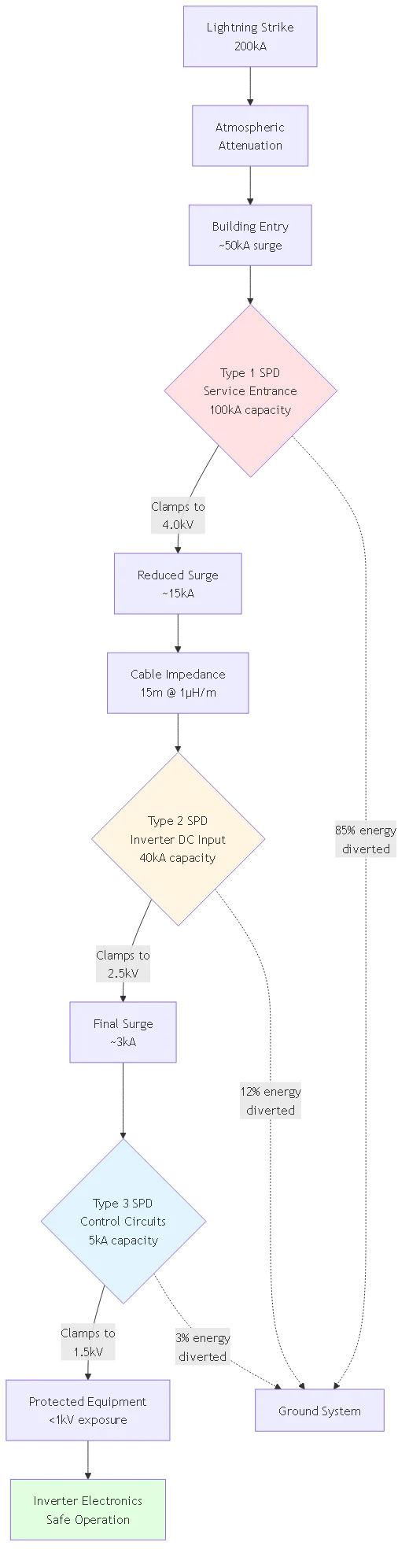
– Protection level: Type 2 reduces 10kA surge to 2.5kV, Type 3 further clamps to 1.5kV for sensitive circuits
🎯 Consejo profesional: Always specify SPD coordination as a system, not individual devices. Many manufacturers offer pre-coordinated SPD sets with tested compatibility and installation instructions. This eliminates coordination calculation requirements and ensures proper operation.
Every meter of wire between the SPD and protected equipment adds inductance that reduces protection effectiveness. Long leads create voltage overshoot that defeats the SPD’s clamping function.
Lead Inductance Impact:
Wire inductance ≈ 1μH per meter
Voltage overshoot = L × (dI/dt)
For 10kA surge with 8μs rise time:
– 0.3m leads: ~375V overshoot (acceptable)
– 1.0m leads: ~1,250V overshoot (marginal)
– 3.0m leads: ~3,750V overshoot (ineffective protection)
Installation Rules:
Ideal: SPD mounted directly at protected equipment terminals with <30cm total lead length (positive + negative ground).Aceptable: Leads under 1.0m using largest practical wire gauge (6 AWG minimum).
Avoid: Leads exceeding 1.5m—consider relocating SPD closer to equipment or using remote SPD with fiber optic isolation.
Lead Routing: Use twisted-pair configuration or run positive/negative leads in close parallel to minimize loop inductance. Never create large wire loops.
SPDs divert surge current to ground—inadequate grounding renders them ineffective regardless of device quality.
Grounding Requirements:
Resistencia a tierra: Achieve <10Ω measured from SPD ground terminal to earth. Lower is better; target <5Ω for Type 1 SPD installations.Ground Conductor Sizing: Minimum 6 AWG copper for residential Type 2 SPDs, 4 AWG for commercial installations, 2 AWG or larger for Type 1 applications.
Método de conexión: Use listed compression lugs or mechanical connectors—never rely on wire nuts or twist-on connections for SPD grounding.
Equipotential Bonding: Connect SPD ground to the main grounding electrode system along with panel frames, racking, and metal conduit. Multiple separate grounds create dangerous ground loops.
⚠️ Advertencia: Testing ground resistance requires a proper 3-wire or 4-wire earth resistance tester. Standard multimeters cannot measure ground resistance accurately. Poor grounding is the #1 cause of SPD protection failure.
SPDs sacrifice themselves protecting equipment. Without monitoring, failed SPDs remain installed providing false security.
Indicator Types:
Mechanical Flag: Visible red/green flag shows SPD operational status. Most reliable but requires visual inspection.
LED Indicator: Green/red lights show status. Requires power connection to operate—won’t indicate failure if circuit is de-energized.
Remote Contact: Dry contact closure signals SPD failure to monitoring system or alarm panel. Essential for commercial systems.
Seccionador: Built-in thermal disconnector isolates failed SPD to prevent short-circuit conditions. Required for Type 1 and Type 2 AC-side SPDs per NEC 285.25.
Inspection Schedule:
– Residential systems: Check indicators every 6 months during routine maintenance
– Commercial systems: Monthly visual check or continuous remote monitoring
– After known surge event: Immediate inspection and testing
– Annual: Professional testing with megohm meter to verify MOV integrity
Problema: Electricians familiar with building electrical work but new to solar use standard AC surge protectors on DC circuits because “they’re rated for the same voltage.”
Por qué falla: AC and DC arcs behave fundamentally differently. AC current crosses zero 120 times per second, naturally extinguishing arcs. DC arcs sustain continuously—once an arc starts in an AC-rated device on DC, it won’t self-extinguish and can cause fires.
Escenarios comunes:
– Using building surge suppressors at solar inverter DC input
– Installing AC-rated SPDs in DC combiner boxes
– Specifying standard lightning arrestors for DC applications
Corrección: Always specify DC-rated SPDs with UL 1449 DC listing or IEC 61643-11 certification. Verify MCOV rating exceeds system Voc × 1.15. DC-rated devices use different internal construction and materials to safely interrupt DC arcs.
Problema: Specifying 600V MCOV SPDs for 600V solar systems without accounting for open-circuit voltage exceeding nameplate ratings.
Por qué falla: A “600V solar system” actually operates at 700-750V open-circuit voltage (cold weather). The SPD continuously conducts at these normal voltages, rapidly degrading MOVs and failing within months.
Escenarios comunes:
– Matching SPD voltage to inverter MPP voltage instead of Voc
– Ignoring temperature coefficient (cold weather voltage rise)
– Using remaining SPD stock from 48V systems on 600V systems
Corrección: Calculate maximum possible Voc: (number of panels) × (single panel Voc) × (cold temperature factor 1.05-1.10). Select SPD MCOV at least 1.15× this calculated voltage. Standard choices: 800V or 1000V MCOV for 600V nominal systems.
Problema: Contractors install SPDs but don’t verify or upgrade grounding systems, leaving inadequate ground paths for surge current dissipation.
Por qué falla: SPDs need low-impedance paths to earth to function. High ground resistance (>25Ω) or long/undersized ground conductors prevent effective surge current diversion. Surge energy has nowhere to go and damages equipment anyway despite SPD presence.
Escenarios comunes:
– Installing SPD but not testing ground resistance
– Using 10 AWG ground wire instead of required 6 AWG minimum
– Connecting SPD ground to isolated ground rod instead of main system ground
– Creating ground loops with multiple separate ground points
Corrección: Before installing SPDs, test ground resistance with proper 3-wire tester—target <10Ω. Use 6 AWG minimum ground conductors (4 AWG for commercial). Keep leads as short as possible (<1m). Connect to main grounding electrode system shared with panels, racking, and equipment grounds.
Problema: Installing multiple SPDs at different locations without ensuring proper coordination between devices, causing one SPD to fail while others don’t activate.
Por qué falla: Uncoordinated SPDs compete for surge current based on installation location and impedance. The “wrong” SPD may activate first, exceeding its capacity while downstream devices with greater capacity never conduct.
Escenarios comunes:
– Installing Type 2 SPDs at both combiner box and inverter with insufficient separation
– Mixing SPDs from different manufacturers without coordination verification
– Placing Type 1 and Type 2 SPDs too close together (<5m)Corrección: Maintain minimum 10m cable distance between Type 1 and Type 2 SPDs for natural inductive decoupling. If closer installation required, use coordinated SPD sets from single manufacturer or add series impedance (inductor 10-20μH). Always specify SPD coordination when designing systems with multiple protection points.
Problema: Installing DC and AC SPDs but leaving communication lines (Ethernet, RS485, WiFi) unprotected, allowing surge entry through monitoring systems.
Por qué falla: Surge current finds all available paths into equipment. Modern inverters have multiple connection points—power terminals AND communication ports. Lightning-induced voltages couple into communication cables just as easily as power cables.
Escenarios comunes:
– Protecting inverter DC/AC but not Ethernet monitoring connection
– Leaving RS485 daisy-chain between inverters unprotected
– Using outdoor WiFi access points without surge protection
Corrección: Install Type 3 SPDs on all communication circuits entering inverters and monitoring equipment. Use shielded cables for communication runs exceeding 10m. Ground cable shields at both ends to equipment chassis. Consider fiber optic isolation for communication runs exceeding 50m in high-risk areas.
Residential System Example (10kW, Moderate Risk):
Unprotected System Risk:
– 20% probability of damaging surge over 25 years
– Average damage cost: $4,500 (inverter + service call + downtime)
– Expected loss value: $900 over system lifetime
SPD Protection Investment:
– Type 2 DC + AC SPDs: $400 installed
– Expected SPD replacement (2×): $200
– Total protection cost: $600
Result: $300 net savings plus peace of mind and warranty protection. Protection economically justified even in moderate-risk scenarios.
Commercial System Example (150kW, High Risk):
Unprotected System Risk:
– 40% probability of damaging surge over 25 years
– Average damage cost: $18,000 (multiple inverters + production loss)
– Expected loss value: $7,200 over system lifetime
Enhanced SPD Protection Investment:
– Type 1+2 coordinated system: $4,500 installed
– Maintenance and replacement: $1,500
– Total protection cost: $6,000
– Insurance premium reduction: -$2,000 (5% annual reduction)
- Net cost: $4,000
Result: $3,200 net savings plus avoided business disruption and insurance compliance. Strong economic justification for comprehensive protection.
| Tamaño del sistema | Protection Cost | Expected Damage (Unprotected) | Break-Even Probability | Economic Decision |
|---|---|---|---|---|
| 5kW Residential | $300-$500 | $2,500-$4,000 | 10-15% | Marginal, code compliance |
| 10kW Residential | $400-$800 | $3,500-$6,000 | 8-12% | Justified at Ng >10 |
| 50kW Commercial | $1,500-$3,000 | $8,000-$15,000 | 12-18% | Strongly justified |
| 200kW Commercial | $4,000-$8,000 | $20,000-$40,000 | 15-25% | Essential protection |
| 1MW+ Utility | $25,000-$100,000 | $100,000-$500,000 | 20-30% | Required for financing |
Información clave: SPD protection economics improve dramatically with system size. Large commercial and utility installations should always invest in comprehensive coordinated protection—the ROI is clear even in moderate-risk zones.
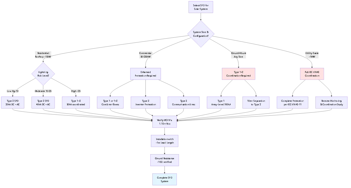
Artículo 690 de NEC.35 requires surge protective devices (SPDs) on ungrounded photovoltaic systems, with Type 2 SPDs being the minimum acceptable protection level for most installations. The specific requirements depend on system configuration and local lightning risk.
For standard residential rooftop systems under 15kW in moderate-risk areas, a Type 2 SPD rated for 20-40kA discharge current at the inverter DC input satisfies code requirements. The SPD must be DC-rated with maximum continuous operating voltage (MCOV) exceeding 1.15 times the system’s open-circuit voltage. Commercial systems over 50kW typically require coordinated Type 1+2 protection with SPDs at both combiner boxes and inverters. Ground-mounted arrays in any location need enhanced protection including Type 1 SPDs due to increased lightning exposure. The selected SPD must carry UL 1449 DC listing or equivalent IEC 61643-11 certification confirming suitability for solar DC applications.
The choice between Type 1 and Type 2 SPDs depends primarily on installation location and lightning exposure level. Type 1 SPDs (Class I) are designed for primary protection at service entrances and locations exposed to direct lightning strikes, with discharge capacities of 25-100kA using the 10/350μs waveform that simulates direct strikes.
Type 2 SPDs (Class II) provide secondary protection at equipment level with 8-40kA capacity using the 8/20μs waveform representing conducted surges. Select Type 1 SPDs for: ground-mounted solar arrays in open fields, array combiner boxes on exposed structures, service entrance protection in high-risk zones (>25 strikes/km²/year), and any installation requiring protection against direct lightning current. Select Type 2 SPDs for: residential rooftop arrays on buildings, inverter DC input protection, inverter AC output protection, and sub-distribution panels. Many commercial installations use both types in coordinated configuration—Type 1 at the combiner box to handle potential direct strikes, followed by Type 2 at the inverter for equipment-level protection with lower voltage clamping.
No, you should never use AC-rated surge protectors on solar DC circuits due to fundamental differences in how AC and DC electrical arcs behave. AC current naturally crosses zero voltage 120 times per second, which helps extinguish electrical arcs automatically. DC current maintains constant polarity without zero-crossings, meaning once an arc starts in an AC-rated device operating on DC, it cannot self-extinguish and may lead to device failure or fire.
AC surge protectors use internal components and ratings based on AC arc interruption characteristics. When subjected to DC voltage, these devices may initially appear to function but will fail catastrophically during actual surge events when sustained DC arcs develop. Always specify DC-rated SPDs with UL 1449 DC listing or IEC 61643-11 certification for solar applications. DC-rated SPDs use different internal construction, enhanced arc-quenching chambers, and materials specifically designed to interrupt sustained DC arcs safely. The voltage rating is also critical—ensure the SPD’s maximum continuous operating voltage (MCOV) exceeds your system’s open-circuit voltage by at least 15% to prevent nuisance operation during normal cold-weather voltage peaks.
SPD replacement intervals depend on surge exposure frequency, device quality, and monitoring capabilities rather than fixed time schedules. Quality Type 2 SPDs in residential applications typically last 5-15 years without major surge events, but devices exposed to frequent minor surges may degrade within 3-5 years.
The key is monitoring SPD health rather than assuming calendar-based replacement. Modern SPDs include end-of-life indicators—visual flags, LED lights, or remote alarm contacts—that signal when the device has sacrificed itself protecting your equipment and needs replacement. Check these indicators every 6 months during routine maintenance. After any known nearby lightning strike or grid disturbance that trips breakers, inspect all SPD indicators immediately. Replace SPDs showing failure indication without delay—failed SPDs provide zero protection. For commercial systems, implement continuous remote monitoring of SPD status through SCADA or building management systems, enabling immediate replacement scheduling. Even if indicators show “good” status, consider replacing SPDs every 8-10 years as preventive maintenance in high-risk areas, as MOV elements can degrade internally without visible external indication. Keep replacement SPDs in stock for critical facilities to minimize downtime when replacement is needed.
SPD failure modes depend on device type and whether thermal disconnectors are installed. Quality Type 2 and Type 3 SPDs typically fail “open circuit”—they stop conducting and provide no further protection, but don’t create short circuits or fire hazards. The solar system continues operating normally without protection.
Type 1 SPDs and some high-current Type 2 devices may fail “short circuit” if they lack proper thermal disconnectors, potentially creating a ground fault that trips breakers or causes overcurrent conditions. This is why NEC 285.25 requires disconnectors for SPDs installed on the load side of service entrance overcurrent protection. Failed SPDs without disconnectors can overheat or ignite if short-circuit failure occurs. The danger of SPD failure isn’t immediate system damage—it’s the loss of protection against subsequent surge events. A failed open-circuit SPD leaves your equipment completely vulnerable to the next lightning strike or utility surge, which could destroy inverters and electronics worth thousands of dollars. This is why SPD end-of-life monitoring is critical. Install SPDs with visible indicators (LED lights or mechanical flags) and check them regularly. For commercial systems, use SPDs with remote alarm contacts connected to monitoring systems for immediate notification of failure. Replace failed SPDs immediately to restore protection—continuing operation with failed SPDs is like driving without insurance after an accident.
Yes, comprehensive solar system protection requires separate SPDs on both DC and AC sides because each side faces different surge threats and operates at different voltages. DC-side SPDs protect the photovoltaic array, DC wiring, and inverter DC input from surges originating at the solar panels—primarily lightning-induced voltages from electromagnetic coupling to the array and nearby strikes.
AC-side SPDs protect the inverter AC output, distribution wiring, and connected loads from surges originating on the utility grid—lightning strikes to utility lines, transformer switching, and fault conditions. The inverter provides some isolation between DC and AC sides, but surge energy can still couple across through parasitic capacitance, control circuits, and grounding systems. Installing only DC-side SPDs leaves your inverter’s AC electronics vulnerable to utility-side surges, while AC-only protection doesn’t address the more frequent DC-side surge threats from array exposure. Proper protection specification includes: Type 2 DC SPD at inverter DC input rated for system Voc, Type 2 AC SPD at inverter AC output rated for grid voltage (single or three-phase), and Type 3 SPDs on communication circuits (Ethernet, RS485) if monitoring systems are installed. The total investment for residential three-point protection is typically $400-$800 installed—modest compared to $5,000-$15,000 in equipment being protected.
SPD voltage rating selection requires calculating your system’s maximum possible open-circuit voltage and adding safety margin to ensure the SPD doesn’t conduct during normal operation. The critical specification is MCOV (maximum continuous operating voltage)—the highest DC voltage the SPD can withstand continuously without degrading.
Calculate required MCOV using this formula: MCOV ≥ (Number of panels in series) × (Single panel Voc) × (Temperature coefficient 1.05-1.10) × (Safety factor 1.15). For example, a string with 20 panels rated 42V Voc each: Maximum Voc = 20 × 42V × 1.08 (cold temp) = 907V; Minimum MCOV = 907V × 1.15 = 1,043V; Select standard SPD: 1,000V or 1,200V MCOV rating. Common residential systems (600V nominal) require 800V or 1,000V MCOV SPDs. Never use SPDs with MCOV below your calculated requirement—undersized SPDs conduct during normal high-voltage conditions (cold mornings, no-load), rapidly degrading the MOV elements and failing within months. After MCOV, verify the voltage protection level (Up) is compatible with your inverter’s surge immunity rating—most modern inverters withstand 4-6kV, providing adequate margin with Type 2 SPDs rated Up ≈ 2.5kV. When in doubt, select the next higher standard voltage rating rather than risking undersized protection.
Effective surge protection for solar systems requires systematic selection of appropriately rated SPDs matched to system configuration, lightning risk, and code requirements. The investment in proper protection is modest compared to equipment replacement costs and operational disruption from surge damage.
Principales conclusiones:
1. Code compliance starts with Type 2 SPDs: NEC 690.35 mandates surge protection on ungrounded PV systems—Type 2 DC-rated SPDs at inverter inputs are minimum acceptable protection for residential installations.
2. Voltage rating is critical: Select SPDs with MCOV exceeding 1.15× system open-circuit voltage to prevent nuisance operation during cold weather—undersizing causes premature failure.
3. System type determines protection level: Residential rooftop arrays typically need Type 2 protection, commercial systems require coordinated Type 1+2, and ground-mounted arrays always need Type 1 primary protection.
4. Coordination maximizes effectiveness: Multiple SPDs work together only when properly coordinated—maintain adequate separation distance or use manufacturer-matched sets to ensure cascade protection.
5. Monitoring prevents silent failure: SPDs sacrifice themselves protecting equipment—install devices with end-of-life indicators and check them regularly to ensure continuous protection.
The most effective approach implements layered protection appropriate to actual risk: basic Type 2 SPDs for low-risk residential systems, enhanced coordinated protection for commercial installations, and comprehensive multi-level systems for high-value or high-exposure arrays. Proper SPD selection combined with quality installation and regular monitoring provides reliable protection throughout the system’s 25+ year lifespan.
Recursos relacionados:
- SPD de CC para sistemas solares: Aplicaciones Tipo 1 vs Tipo 2
- Understanding DC SPD: MOV vs GDT Protection Technology
- 1000V DC SPD Selection: Utility-Scale System Protection
Ready to specify surge protection for your solar installation? Contact our technical team for system-specific SPD recommendations based on your array configuration, local lightning density, and equipment protection requirements. We provide coordinated SPD solutions meeting all NEC and IEC standards with complete installation documentation.
Última actualización: March 2026
Autor: Equipo técnico de SYNODE
Revisado por: Departamento de Ingeniería Eléctrica
Palabra clave: surge protection for solar systems
URL Slug: surge-protection-solar-systems-spd-selection-guide
Meta Título: Surge Protection for Solar Systems: Complete SPD Selection Guide 2025
Meta Descripción: Master surge protection for solar systems with expert SPD type selection matrices. Compare Type 1, 2, and 3 devices, coordinate protection levels, and meet NEC 690.35 requirements.
Nivel de contenido: Nivel 2 (Contenido estándar)
Embudo de conversión: Mitad del embudo (Consideración)
Número de palabras objetivo: 2800-4000 palabras
Objetivo Diagramas de sirena: 3
Por favor, configúrelos en los ajustes de Rank Math, luego borre esta casilla antes de publicar.
NEC Article 690.35 requires surge protective devices (SPDs) on ungrounded photovoltaic systems, with Type 2 SPDs being the minimum acceptable protection level for most installations. The specific requirements depend on system configuration and local lightning risk. For standard residential rooftop systems under 15kW in moderate-risk areas, a Type 2 SPD rated for 20-40kA discharge current at the inverter DC input satisfies code requirements. The SPD must be DC-rated with maximum continuous operating voltage (MCOV) exceeding 1.15 times the system’s open-circuit voltage. Commercial systems over 50kW typically require coordinated Type 1+2 protection with SPDs at both combiner boxes and inverters. Ground-mounted arrays in any location need enhanced protection including Type 1 SPDs due to increased lightning exposure. The selected SPD must carry UL 1449 DC listing or equivalent IEC 61643-11 certification confirming suitability for solar DC applications.
The choice between Type 1 and Type 2 SPDs depends primarily on installation location and lightning exposure level. Type 1 SPDs (Class I) are designed for primary protection at service entrances and locations exposed to direct lightning strikes, with discharge capacities of 25-100kA using the 10/350μs waveform that simulates direct strikes. Type 2 SPDs (Class II) provide secondary protection at equipment level with 8-40kA capacity using the 8/20μs waveform representing conducted surges. Select Type 1 SPDs for: ground-mounted solar arrays in open fields, array combiner boxes on exposed structures, service entrance protection in high-risk zones (>25 strikes/km²/year), and any installation requiring protection against direct lightning current. Select Type 2 SPDs for: residential rooftop arrays on buildings, inverter DC input protection, inverter AC output protection, and sub-distribution panels. Many commercial installations use both types in coordinated configuration—Type 1 at the combiner box to handle potential direct strikes, followed by Type 2 at the inverter for equipment-level protection with lower voltage clamping.
No, you should never use AC-rated surge protectors on solar DC circuits due to fundamental differences in how AC and DC electrical arcs behave. AC current naturally crosses zero voltage 120 times per second, which helps extinguish electrical arcs automatically. DC current maintains constant polarity without zero-crossings, meaning once an arc starts in an AC-rated device operating on DC, it cannot self-extinguish and may lead to device failure or fire. AC surge protectors use internal components and ratings based on AC arc interruption characteristics. When subjected to DC voltage, these devices may initially appear to function but will fail catastrophically during actual surge events when sustained DC arcs develop. Always specify DC-rated SPDs with UL 1449 DC listing or IEC 61643-11 certification for solar applications. DC-rated SPDs use different internal construction, enhanced arc-quenching chambers, and materials specifically designed to interrupt sustained DC arcs safely. The voltage rating is also critical—ensure the SPD’s maximum continuous operating voltage (MCOV) exceeds your system’s open-circuit voltage by at least 15% to prevent nuisance operation during normal cold-weather voltage peaks.
SPD replacement intervals depend on surge exposure frequency, device quality, and monitoring capabilities rather than fixed time schedules. Quality Type 2 SPDs in residential applications typically last 5-15 years without major surge events, but devices exposed to frequent minor surges may degrade within 3-5 years. The key is monitoring SPD health rather than assuming calendar-based replacement. Modern SPDs include end-of-life indicators—visual flags, LED lights, or remote alarm contacts—that signal when the device has sacrificed itself protecting your equipment and needs replacement. Check these indicators every 6 months during routine maintenance. After any known nearby lightning strike or grid disturbance that trips breakers, inspect all SPD indicators immediately. Replace SPDs showing failure indication without delay—failed SPDs provide zero protection. For commercial systems, implement continuous remote monitoring of SPD status through SCADA or building management systems, enabling immediate replacement scheduling. Even if indicators show good status, consider replacing SPDs every 8-10 years as preventive maintenance in high-risk areas, as MOV elements can degrade internally without visible external indication.
SPD failure modes depend on device type and whether thermal disconnectors are installed. Quality Type 2 and Type 3 SPDs typically fail open circuit—they stop conducting and provide no further protection, but don’t create short circuits or fire hazards. The solar system continues operating normally without protection. Type 1 SPDs and some high-current Type 2 devices may fail short circuit if they lack proper thermal disconnectors, potentially creating a ground fault that trips breakers or causes overcurrent conditions. This is why NEC 285.25 requires disconnectors for SPDs installed on the load side of service entrance overcurrent protection. Failed SPDs without disconnectors can overheat or ignite if short-circuit failure occurs. The danger of SPD failure isn’t immediate system damage—it’s the loss of protection against subsequent surge events. A failed open-circuit SPD leaves your equipment completely vulnerable to the next lightning strike or utility surge, which could destroy inverters and electronics worth thousands of dollars. This is why SPD end-of-life monitoring is critical. Install SPDs with visible indicators and check them regularly. For commercial systems, use SPDs with remote alarm contacts connected to monitoring systems for immediate notification of failure.
Yes, comprehensive solar system protection requires separate SPDs on both DC and AC sides because each side faces different surge threats and operates at different voltages. DC-side SPDs protect the photovoltaic array, DC wiring, and inverter DC input from surges originating at the solar panels—primarily lightning-induced voltages from electromagnetic coupling to the array and nearby strikes. AC-side SPDs protect the inverter AC output, distribution wiring, and connected loads from surges originating on the utility grid—lightning strikes to utility lines, transformer switching, and fault conditions. The inverter provides some isolation between DC and AC sides, but surge energy can still couple across through parasitic capacitance, control circuits, and grounding systems. Installing only DC-side SPDs leaves your inverter’s AC electronics vulnerable to utility-side surges, while AC-only protection doesn’t address the more frequent DC-side surge threats from array exposure. Proper protection specification includes: Type 2 DC SPD at inverter DC input rated for system Voc, Type 2 AC SPD at inverter AC output rated for grid voltage, and Type 3 SPDs on communication circuits if monitoring systems are installed.
SPD voltage rating selection requires calculating your system’s maximum possible open-circuit voltage and adding safety margin to ensure the SPD doesn’t conduct during normal operation. The critical specification is MCOV (maximum continuous operating voltage)—the highest DC voltage the SPD can withstand continuously without degrading. Calculate required MCOV using this formula: MCOV ≥ (Number of panels in series) × (Single panel Voc) × (Temperature coefficient 1.05-1.10) × (Safety factor 1.15). For example, a string with 20 panels rated 42V Voc each: Maximum Voc = 20 × 42V × 1.08 (cold temp) = 907V; Minimum MCOV = 907V × 1.15 = 1,043V; Select standard SPD: 1,000V or 1,200V MCOV rating. Common residential systems (600V nominal) require 800V or 1,000V MCOV SPDs. Never use SPDs with MCOV below your calculated requirement—undersized SPDs conduct during normal high-voltage conditions, rapidly degrading the MOV elements and failing within months.