Dirección
304 North Cardinal
Dorchester Center, MA 02124
Horas de trabajo
De lunes a viernes: de 7.00 a 19.00 horas
Fin de semana: 10.00 A 17.00 HORAS
Dirección
304 North Cardinal
Dorchester Center, MA 02124
Horas de trabajo
De lunes a viernes: de 7.00 a 19.00 horas
Fin de semana: 10.00 A 17.00 HORAS

DC surge protective devices handle fundamentally different physics than AC units. In a 1200 VDC battery energy storage system commissioned in Jiangsu (2023), engineers replaced AC-rated SPDs with DC-specific models after the AC units failed to extinguish follow-current—DC arcs don’t self-extinguish at zero-crossing because there is no zero-crossing.
A proper DC SPD uses varistor stacks rated for continuous DC voltage plus a series disconnect (thermal or spark-gap) that physically isolates the varistor after energy absorption, preventing thermal runaway. IEC 61643-31 governs DC SPD testing; key differences from IEC 61643-11 (AC) include higher energy absorption per pulse (Wmax in kJ) and stricter leakage current limits at maximum continuous operating voltage (MCOV).
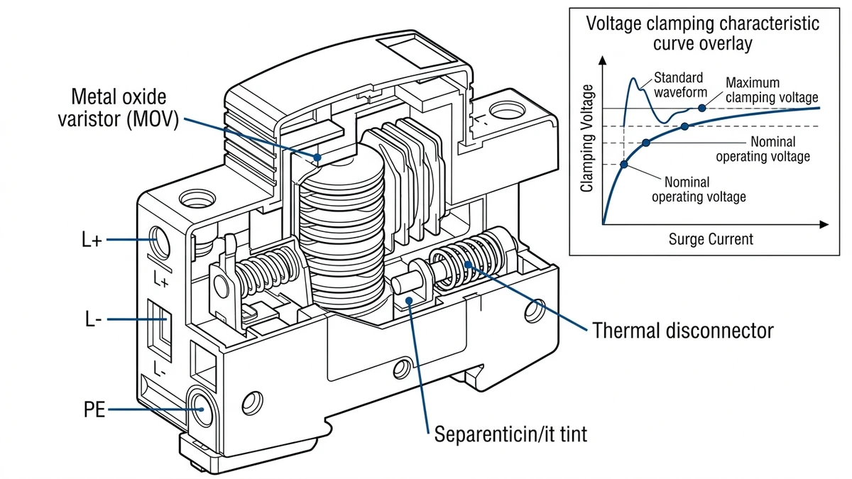
For photovoltaic systems above 1000 VDC, the voltage protection level (Up) must stay below the insulation coordination level of connected inverters and DC optimizers—typically ≤4 kV for 1500 VDC strings. The thermal disconnector must physically separate the varistor from the circuit when degraded, not just open a contact, and withstand system MCOV without re-striking.
: DC vs AC SPD Internal Schematic Comparison
– Style: Scientific journal illustration, white background, vector line art
– Content: Side-by-side cutaway views showing:
* Left panel: AC SPD with single varistor disk, no series disconnect (arc path shown extinguishing at zero-crossing waveform)
* Right panel: DC SPD with varistor stack + thermal disconnector mechanism (arc path shown continuing without zero-crossing, disconnector activating)
* Callouts in Sinobreaker dark blue #003F8F: “Zero-crossing extinction (AC only)”, “Thermal disconnector (DC required)”, “Varistor stack for DC voltage”, “Follow-current path”
– Dimensions: 1200×600 px, horizontal layout
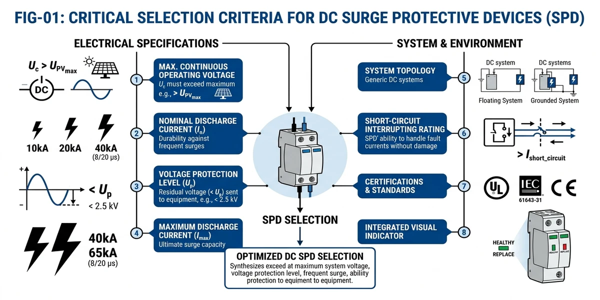
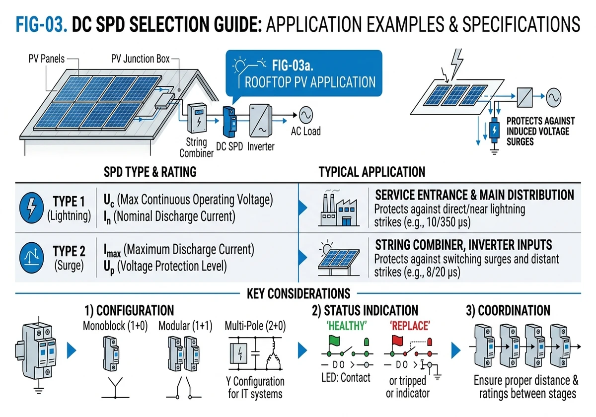
Type 1 devices install at service entrance or main DC distribution points. They’re tested with 10/350 µs waveform simulating direct lightning strikes, with impulse current ratings (Iimp) from 12.5 kA to 25 kA per pole. Use Type 1 for ground-mount solar farms, rooftop arrays above 100 kWp, and ESS containers with external battery racks where direct strike risk exists.
Type 2 devices install at sub-distribution or equipment inputs. They’re tested with 8/20 µs waveform simulating induced surges, with maximum discharge current (Imax) from 20 kA to 40 kA per pole. Use Type 2 for string-level combiner boxes, inverter DC inputs, and charge controller protection where the primary threat is switching transients and inductive coupling.
| Condición | Recommended Type |
|---|---|
| External LPS present (air terminals, down conductors) | Type 1 at main DC bus + Type 2 at equipment |
| Keraunic level >40 days/year, no external LPS | Type 1 at main distribution |
| Urban rooftop <50 kWp, low lightning exposure | Type 2 alone (verify with IEC 62305-2 risk assessment) |
| Cable runs >100 meters between distribution and equipment | Type 1 + Type 2 cascaded with ≥10m separation |
In a 20 MW agrivoltaic project in Shandong (2024), cascaded protection (Type 1 at DC combiner room + Type 2 at each inverter) reduced surge-related inverter failures from 8 events/year to zero over 18 months of operation. The Type 1 units absorbed direct strike energy (measured peak: 18 kA), while Type 2 units clamped residual transients below 3.2 kV at inverter terminals.
[Expert Insight: Protection Zone Transitions]
– Lightning protection zones (LPZ) define where different SPD types install—Type 1 at LPZ 0A→1 boundary handles direct strikes, Type 2 at LPZ 1→2 manages induced surges
– Coordination distance between cascaded SPDs must exceed 10 meters of cable or include series inductance ≥10 µH to prevent simultaneous activation
– In utility-scale installations, remote monitoring via Modbus RTU reduces mean time to repair from 72 hours to under 9 hours by alerting teams before complete SPD failure
MCOV must exceed the system’s maximum DC voltage under all conditions. The formula accounts for temperature effects on module open-circuit voltage:
Fórmula:
MCOV ≥ Voc(STC) × Temperature coefficient × Safety margin
Worked Example (1500 VDC PV system):
– Module Voc at STC: 49.5 V
– String configuration: 30 modules in series
– Voc at -10°C: 49.5 V × 30 × 1.12 (temp coefficient) = 1663 VDC
– Required MCOV: 1663 V × 1.1 (safety margin) = 1829 VDC minimum
– Select SPD with MCOV = 1900 VDC (next standard rating)
Common MCOV Ratings:
| Tensión del sistema | Recommended MCOV | Aplicación típica |
|---|---|---|
| 600 VDC | 750 VDC | Residential PV, small ESS |
| 1000 VDC | 1200 VDC | Commercial rooftop PV |
| 1500 VDC | 1800–1900 VDC | Utility-scale PV, large ESS |
In a Qinghai solar farm (2022), SPDs rated for 1200 VDC MCOV were installed on a 1500 VDC system. Winter morning Voc peaks reached 1680 VDC, causing varistor degradation and 14 SPD failures within 6 months—replacement with 1900 VDC MCOV units eliminated further failures.
Up is the maximum voltage the SPD allows to pass through during a surge event. It must coordinate with equipment insulation withstand voltage, maintaining at least 20% margin.
Coordination Table:
| Equipos protegidos | Insulation Withstand | Max Allowable Up |
|---|---|---|
| String inverters (1500 VDC) | 5.0 kV | 4.0 kV |
| Central inverters (1500 VDC) | 5.5 kV | 4.5 kV |
| DC optimizers | 4.5 kV | 3.5 kV |
| Battery management systems | 3.8 kV | 3.0 kV |
Select SPD with Up at least 20% below equipment withstand voltage to account for repetitive surge stress and temperature effects—varistor clamping voltage increases approximately 0.05%/°C.
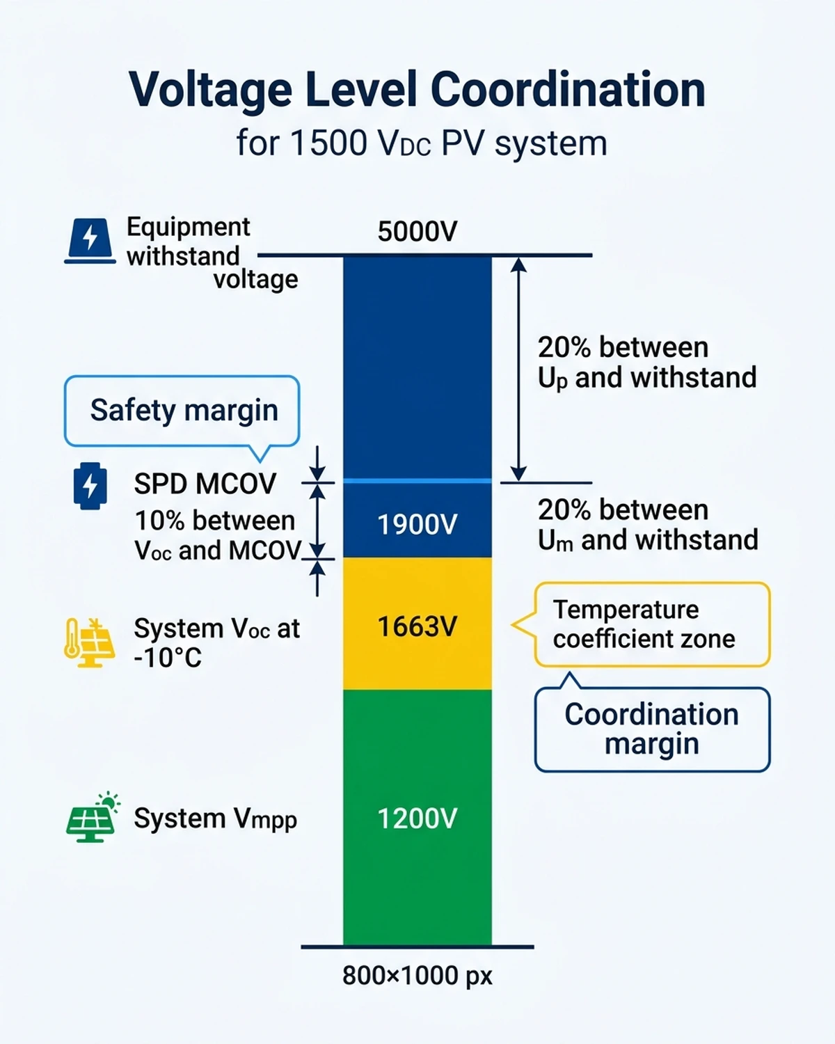
: MCOV vs System Voltage Coordination Diagram
– Style: Infographic, flat design, Sinobreaker brand colors
– Content: Vertical bar chart showing voltage levels:
* Bottom bar: System Vmpp (green, 1200V example)
* Middle bar: System Voc at -10°C (yellow, 1663V)
* Upper bar: SPD MCOV (dark blue #003F8F, 1900V)
* Top reference line: Equipment withstand voltage (5000V)
* Arrows showing safety margins: 10% between Voc and MCOV, 20% between Up and withstand
* Callout boxes: “Temperature coefficient zone”, “Safety margin”, “Coordination margin”
– Dimensions: 800×1000 px, vertical layout
Size Iimp based on lightning protection zone (LPZ) transition and site exposure:
Sizing Guide:
- High exposure (open fields, coastal areas, mountain sites): Iimp ≥ 25 kA (10/350 µs)
- Medium exposure (suburban areas, industrial parks): Iimp ≥ 15 kA
- Low exposure (urban areas, shielded by tall structures): Iimp ≥ 12.5 kA
For sites with soil resistivity >500 Ω·m or Keraunic level >60 days/year, increase Iimp by one rating step.
For a 1000 VDC combiner box with 8 strings (each 12A Isc) and typical cable impedance of 0.5 Ω, Imax = 40 kA per pole provides adequate margin for induced surges from nearby strikes. Systems with cable runs exceeding 50 meters or high-frequency inverter switching (>20 kHz) should use Imax ≥ 60 kA.
W/R represents energy absorption capability per unit resistance, critical for PV systems with long cable runs. IEC 61643-31 requires:
– Type 1: W/R ≥ 2.5 kJ/Ω
– Type 2: W/R ≥ 1.0 kJ/Ω
In a 5 MW carport solar installation (Guangdong, 2023), SPDs with W/R = 1.2 kJ/Ω survived a direct strike that induced 380 V/m field strength across 150-meter DC cable runs. Post-event testing showed varistor degradation of only 8%, well within the 20% replacement threshold.
[Expert Insight: Energy Coordination]
– Cascaded SPD systems must coordinate energy sharing—upstream Type 1 devices absorb 70-80% of surge energy, downstream Type 2 units handle residual transients
– Lead length matters: every meter of connection cable adds approximately 1 kV to effective Up due to inductive voltage drop at 10 kA/µs surge rise rates
– Metal oxide varistor (MOV) technology dominates DC applications with sub-nanosecond response times and energy absorption up to 500 J per varistor block in 1500V systems
CM protection connects between DC conductors and ground (L+/PE, L-/PE). It protects against lightning-induced ground potential rise, where strike current flowing through earth creates voltage differences between equipment grounds. IEC 62305-4 requires CM protection for all systems with external lightning protection or metallic service entrance conductors.
DM protection connects between DC+ and DC- conductors (L+/L-). It protects against switching transients from inverter MPPT circuits, inductive coupling from nearby AC equipment, and common-mode-to-differential-mode conversion in long cable runs. Recommend DM protection for:
– Cable runs >50 meters between combiner and inverter
– Inverters with high-frequency switching (>20 kHz)
– Co-location with motor drives, welding equipment, or EV chargers
Most DC SPDs use 3-pole configuration (L+, L-, PE) with internal varistor network providing both CM and DM protection. Verify the manufacturer specifies separate Up values for CM mode (L+/PE, L-/PE) and DM mode (L+/L-)—they differ by 20-40% due to varistor series/parallel arrangements.
: 3-Pole SPD Wiring Diagram with CM/DM Protection Paths
– Style: Scientific journal illustration, white background, vector line art
– Content: Schematic showing:
* DC source (left): L+ and L- conductors from PV strings
* SPD center block with three varistor symbols (L+/PE, L-/PE, L+/L-)
* Protected load (right): Inverter DC input terminals
* Ground/PE conductor (bottom) with earth symbol
* Current flow arrows in bright blue #2196F3 showing:
– CM surge path: L+ → PE (dashed line)
– DM surge path: L+ → L- (solid line)
* Callouts in dark blue #003F8F: “Common mode protection”, “Differential mode protection”, “Thermal disconnector”, “PE grounding point”
– Dimensions: 1000×700 px, horizontal layout
AC SPDs rely on current zero-crossing to extinguish arcs every 8.3 ms (60 Hz) or 10 ms (50 Hz). At 1000 VDC, a 20 kA AC-rated SPD may only handle 8 kA DC before thermal runaway because the arc never extinguishes naturally. Always verify “DC” marking on the device nameplate and request IEC 61643-31 test report showing Imax specified with 8/20 µs waveform at system voltage.
Varistor clamping voltage increases 0.05%/°C. An SPD with Up = 3.8 kV at 25°C may reach 4.2 kV at 65°C—common in outdoor combiner boxes under direct sunlight. For ambient temperatures exceeding 40°C, select SPD with Up at least 15% below equipment withstand voltage to maintain coordination margin across the operating temperature range.
Installing only one SPD at the inverter leaves string wiring and combiner boxes unprotected. A strike to the array frame induces surges that propagate through DC cables, potentially exceeding equipment withstand voltage before reaching the inverter-level SPD. Use cascaded protection with Type 1 at main distribution and Type 2 at equipment, maintaining ≥10 meters of cable between devices per IEC 61643-12 coordination requirements.
Main DC Distribution (Type 1):
– MCOV: 1900 VDC (1653 V × 1.15 safety margin)
– Iimp: 25 kA (10/350 µs) per pole—high lightning exposure, coastal location
– Up: ≤3.8 kV (inverter withstand: 6 kV per datasheet, 20% coordination margin)
– Configuration: 3-pole (L+, L-, PE) with CM + DM protection
– Monitoring: Modbus RTU for building management system integration
– Product: https://sinobreaker.com/surge-protection-device/
String Combiner Boxes (Type 2):
– MCOV: 1500 VDC (adequate for 1476 V nominal Voc)
– Imax: 40 kA (8/20 µs) per pole
– Up: ≤3.5 kV (DC optimizer withstand: 4.5 kV, 22% coordination margin)
– Configuration: 3-pole with DM protection for 80-meter cable run
– Quantity: 6 units (one per rooftop combiner box, each serving 5 strings)
Physical separation of 80 meters between Type 1 and Type 2 devices exceeds the 10-meter coordination distance required by IEC 61643-12. Grounding uses 10 mm² Cu conductor to building ground grid (measured resistance: 4.2 Ω).
After 14 months of operation through two typhoon seasons, zero surge-related failures recorded. The monitoring system logged 8 Type 1 activation events (peak currents: 12-19 kA) and 34 Type 2 activation events (peak currents: 6-14 kA), all successfully clamped below equipment withstand voltage. Pre-installation (2022),


