Address
304 North Cardinal
St. Dorchester Center, MA 02124
Work Hours
Monday to Friday: 7AM - 7PM
Weekend: 10AM - 5PM
Address
304 North Cardinal
St. Dorchester Center, MA 02124
Work Hours
Monday to Friday: 7AM - 7PM
Weekend: 10AM - 5PM


Lightning strikes deliver 30,000 amperes of current and temperatures exceeding 50,000°F in microseconds—enough energy to vaporize metal conductors and ignite fires. For rooftop solar installations, the elevated metal structures create preferential strike points, increasing lightning risk by 40-60% compared to unobstructed roofs. Air termination systems—the first line of defense in lightning protection—must capture these strikes safely before they damage expensive PV equipment or penetrate building structures.
Designing effective air termination for solar installations requires balancing two competing objectives: providing adequate lightning protection while avoiding shadowing that reduces energy production. The IEC 62305 standard defines four protection levels (LPL I-IV) with corresponding capture geometries, but PV systems introduce unique challenges. Module frames create conductive pathways, mounting structures alter electrical bonding requirements, and installer access needs complicate traditional lightning rod placement.
This technical guide explains air termination design principles specifically for photovoltaic installations. You’ll learn the rolling sphere method for determining protection coverage, protection angle calculations for rod placement, and PV-specific modifications addressing module integration. Whether designing residential systems under 10kW or utility-scale arrays exceeding 1MW, proper air termination design prevents the 85% of lightning damage that occurs at strike points.
💡 Critical Insight: The shift from isolated lightning rods to integrated air termination networks—where PV module frames participate in the protection system—represents the most significant advancement in solar lightning protection since grounding standards were established in NEC 690.
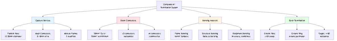
Air termination refers to the elevated conductors deliberately positioned to intercept lightning strikes before they contact protected structures or equipment. In PV systems, air termination serves dual purposes: capturing direct strikes to prevent structural damage and providing controlled discharge paths that protect sensitive electronic equipment from surge damage.
Air Termination System (ATS): Capture devices including lightning rods, mesh conductors, or conductive building components that intercept lightning flashes. This is the visible portion of protection systems—the metal points extending above protected structures.
Down Conductor System: Vertical and horizontal conductors that route captured lightning current from air termination to ground electrodes. Multiple down conductors distributed around structure perimeter prevent side-flashing and reduce magnetic field intensity.
Earth Termination System (Grounding): Underground electrode network that dissipates lightning energy into earth without creating dangerous ground potential rises. Typical resistance target: <10Ω for commercial systems, <25Ω residential.
Solar arrays fundamentally alter building lightning vulnerability through three mechanisms:
Elevated conductor exposure (primary factor): Module frames extend 6-12 inches above roof surfaces, creating preferred strike points. Lightning attachment occurs where electric field gradients are steepest—elevated metal structures concentrate field lines, increasing strike probability 3-5x compared to flat roofs.
Increased ground footprint: Large arrays (>50kW) cover 400-2000m² of roof area, expanding the structure’s lightning collection area. Strike probability increases proportionally with horizontal dimensions—a 100m × 20m array has 5x the strike risk of a 10m × 10m residential installation.
Conductive path creation: Interconnected module frames and mounting rails create long conductive pathways. Without proper air termination, strikes to array edges can propagate through these conductors, damaging equipment hundreds of feet from the actual strike point.
Real-World Context: A 2019 North Carolina study found that PV systems without dedicated air termination experienced lightning damage at rates 4.2x higher than properly protected installations—despite all systems meeting basic NEC grounding requirements. Air termination is not optional for commercial solar.
The IEC 62305 series defines lightning protection system (LPS) design requirements based on risk assessment and desired protection efficacy. Understanding these protection levels is essential for specifying air termination performance.
LPL I (98% Protection Efficiency)
– Application: Critical infrastructure, hospitals, data centers, high-value installations
– Rolling sphere radius: 20 meters
– Protection angle: 25° at 20m height
– Maximum mesh size: 5m × 5m
– Minimum current capture: 200kA (99th percentile strikes)
LPL II (95% Protection Efficiency)
– Application: Commercial buildings, medium-risk industrial facilities
– Rolling sphere radius: 30 meters
– Protection angle: 35° at 20m height
– Maximum mesh size: 10m × 10m
– Minimum current capture: 150kA
LPL III (90% Protection Efficiency)
– Application: Standard commercial/industrial buildings, large residential
– Rolling sphere radius: 45 meters
– Protection angle: 45° at 20m height
– Maximum mesh size: 15m × 15m
– Minimum current capture: 100kA
LPL IV (80% Protection Efficiency)
– Application: Low-risk structures, agricultural buildings, small residential
– Rolling sphere radius: 60 meters
– Protection angle: 55° at 20m height
– Maximum mesh size: 20m × 20m
– Minimum current capture: 100kA
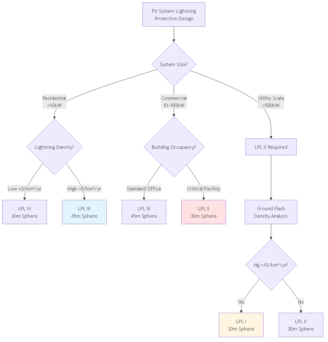
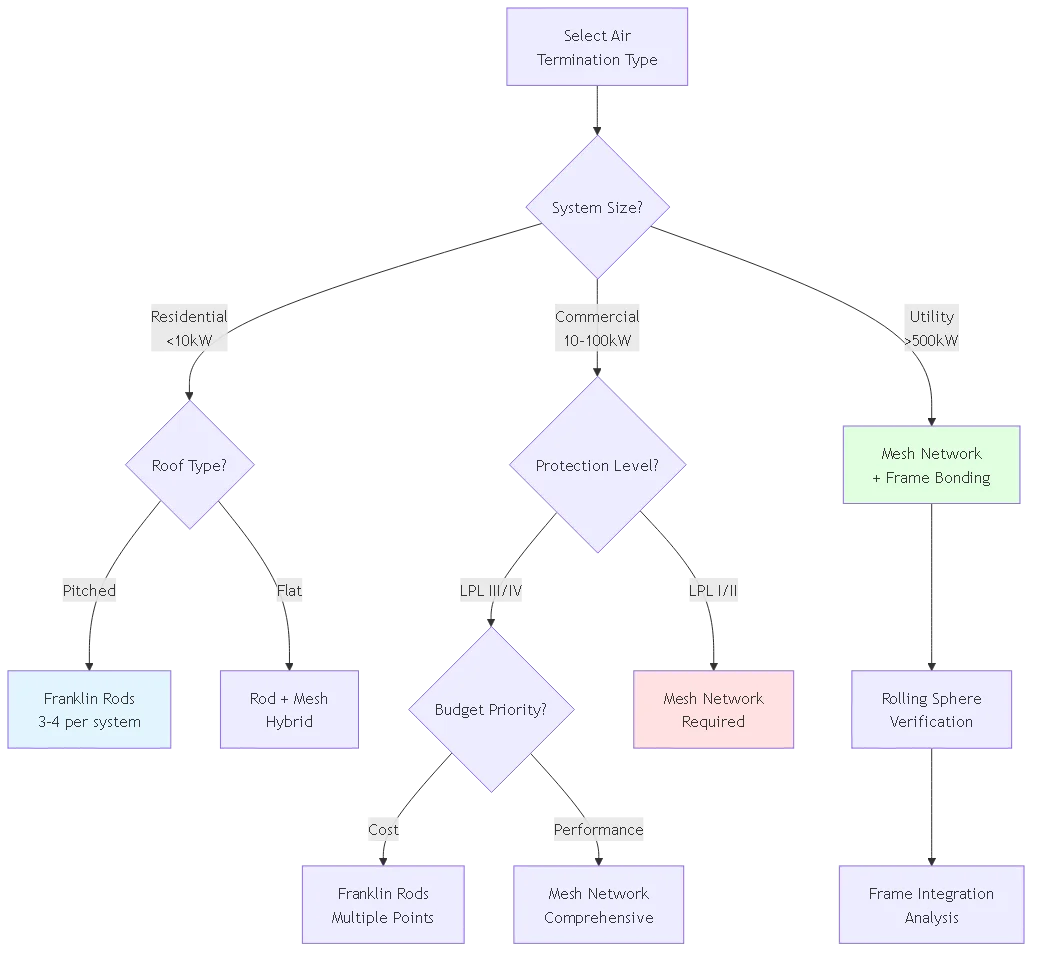
Residential systems (<10kW): Typically LPL III or IV depending on regional lightning density. In high-flash-density regions (>5 strikes/km²/year), specify LPL III minimum.
Commercial rooftop (10-100kW): LPL II or III based on building occupancy and equipment value. Financial institutions and healthcare facilities require LPL II.
Ground-mount utility (>500kW): LPL II minimum due to large ground footprint and equipment concentration. Critical substations may require LPL I.
Calculation factors:
– Lightning ground flash density (Ng): Obtained from regional isokeraunic maps
– Structure dimensions and height
– Equipment replacement cost vs protection system cost
– Occupancy risk (life safety considerations)
⚠️ Important: Protection level selection affects insurance premiums. Many commercial property insurers require LPL II certification for solar installations exceeding 100kW to maintain coverage.
The rolling sphere method (RSM) provides the geometric foundation for air termination design. This approach models lightning attachment behavior by “rolling” an imaginary sphere of specified radius over the structure—any point the sphere touches without contacting air termination devices requires additional protection.
Lightning leaders propagate from clouds toward ground in 50-meter steps, pausing briefly between advances. At the final step distance, streamers launch from ground-based conductors toward the descending leader. Attachment occurs where these streamers intercept the leader—typically from the highest local conductor.
The rolling sphere radius represents this critical streamer launch distance. For LPL I (20m radius), streamers can originate from any point within 20 meters of the final leader position. This means protection devices must be positioned such that no unprotected surface lies within 20m of any possible final leader location.
Step 1: Establish Rolling Sphere Radius
Select radius based on IEC 62305 protection level:
– LPL I: R = 20m
– LPL II: R = 30m
– LPL III: R = 45m
– LPL IV: R = 60m
Step 2: Create 3D Model
Generate accurate dimensional model including:
– Building structure with roof geometry
– PV array layout with module heights above roof
– Existing lightning rods or conductive elements
– Parapet walls, HVAC equipment, other roof obstructions
Step 3: “Roll” Sphere Over Model
Conceptually roll the sphere over the structure surface. The sphere must never contact:
– Roof surfaces outside protection zone
– PV module surfaces (unless specifically designed as air termination)
– Electrical equipment (inverters, combiner boxes, conduit)
– Non-conductive building elements requiring protection
Where sphere contacts these elements, protection gap exists.
Step 4: Position Air Termination
Add lightning rods, mesh conductors, or elevated conductors at locations where sphere would contact unprotected surfaces. Iteratively adjust positions until sphere contacts only:
– Air termination devices
– Down conductors
– Grounded structural steel designated as protection components
– Ground plane
System specifications:
– Roof: 30m × 15m flat membrane
– Array: 100kW, 300 modules in 10 rows
– Module tilt: 10° facing south
– Protection level: LPL III (45m sphere)
– Existing parapets: 1.2m height on north/south edges
Analysis:
1. Roll 45m sphere from west edge—sphere first contacts west parapet
2. Continue rolling east—sphere clears tilted modules (max height 1.5m)
3. At east edge, sphere contacts east parapet
4. Roll sphere north-south along centerline—remains above modules until encountering parapets
Conclusion: Existing parapets provide adequate air termination along north/south perimeters. East/west perimeters require lightning rods spaced ≤30m apart to prevent sphere touchdown between protection points (calculated using protection angle method).
While the rolling sphere method defines protection zones, the protection angle method provides simplified calculations for rod spacing and coverage. This approach works well for structures with regular geometry but requires RSM verification for complex shapes.
The protection angle (α) defines the cone of protection below a vertical lightning rod:
At ground level (h = 0):
– LPL I: α = 25° (at h=20m)
– LPL II: α = 35° (at h=20m)
– LPL III: α = 45° (at h=20m)
– LPL IV: α = 55° (at h=20m)
Protection angle decreases with height above ground. For rods at height H protecting objects at height h:
α(h) = α₀ × [1 – (h/H)^0.6]
Where α₀ is the angle from the table above.
For single rod protecting flat surface at height h:
Protection radius r = (H – h) × tan(α)
Example: LPL III system, rod height H = 3m above roof protecting modules at h = 0.5m:
– α = 45° at ground level
– Effective angle at 0.5m: α ≈ 43°
– Protection radius: r = (3 – 0.5) × tan(43°) = 2.33m
This rod protects a circle of radius 2.33m around its base. For rectangular coverage, multiple rods required with spacing ≤2r to ensure overlap.
The protection angle method becomes unreliable when:
– Protected surface height exceeds 60% of rod height (h/H > 0.6)
– Rod spacing exceeds 2× protection radius
– Complex roof geometry creates shadowing between rods
– Objects being protected have significant horizontal extent
In these cases, revert to rolling sphere method for accurate analysis.
| Protection Level | Rod Height (m) | Protection Angle | Max Coverage Radius |
|---|---|---|---|
| LPL I | 3m above roof | 25° | 1.4m (at 0.5m height) |
| LPL II | 3m above roof | 35° | 1.75m (at 0.5m height) |
| LPL III | 3m above roof | 45° | 2.5m (at 0.5m height) |
| LPL IV | 3m above roof | 55° | 3.6m (at 0.5m height) |
🎯 Pro Tip: For residential installations where aesthetics matter, position lightning rods behind parapet walls or integrate them with existing roof penetrations (chimneys, vent stacks) to minimize visual impact while maintaining protection coverage.

Different air termination approaches suit different installation contexts. Selection depends on array size, roof type, aesthetic requirements, and protection level.
Design: Single vertical conductor extending 0.3-6m above protected surface, typically 12-20mm diameter copper or aluminum alloy rod.
Advantages:
– Simple installation, low cost ($50-200 per rod)
– Minimal visual impact (small footprint)
– Effective for point protection of specific equipment
– Easy integration with existing roof penetrations
Disadvantages:
– Limited protection radius (2-4m typical)
– Multiple rods required for large arrays
– Maintenance access challenging on pitched roofs
– Wind loading on tall rods requires structural analysis
Best for: Residential systems (<10kW), small commercial rooftop arrays where aesthetic considerations limit mesh deployment.Installation note: Rod bases must connect to down conductor with minimum 70mm² aluminum or 50mm² copper conductor. Use mechanical compression fittings, never solder (lightning current vaporizes solder).
Design: Grid of horizontal conductors (typically 8-10mm diameter) spanning protected area with maximum mesh spacing per IEC 62305 (5m × 5m for LPL I, 20m × 20m for LPL IV).
Advantages:
– Comprehensive area coverage
– Multiple capture points reduce side-flash risk
– Lower profile than rod systems (50-150mm above surface)
– Integrated with walkway systems for maintenance access
Disadvantages:
– Higher material cost ($8-15/m² installed)
– Complex installation on tilted arrays
– Shading impact if positioned above modules
– Interference with future array expansion
Best for: Large commercial rooftops (>100kW), ground-mount utility systems where comprehensive coverage justifies cost.
PV-specific consideration: Position mesh conductors between module rows rather than above modules to avoid shading losses. Use aluminum mesh compatible with module frame alloys to prevent galvanic corrosion.
Design: Enhanced air termination device with active ionization claimed to extend protection radius 2-4× conventional rods.
Controversy: IEC 62305 does NOT recognize ESE devices as providing enhanced protection. Many national standards (NFPA 780, Australian AS/NZS 1768) explicitly reject ESE efficacy claims. Use ESE only where local authority explicitly approves and design verification uses conventional rolling sphere method.
Advantages (claimed):
– Reduced number of terminals required
– Lower installation cost due to fewer penetrations
Disadvantages:
– Higher unit cost ($500-2000 vs $50-200 conventional)
– Unproven performance claims
– Not accepted by many insurance underwriters
– Risk of underprotection if claimed radius relied upon
Recommendation: Avoid ESE devices for PV installations. Conventional Franklin rods and mesh provide proven, code-compliant protection at lower cost.
Concept: Integrate grounded module frames into the air termination system rather than installing separate capture devices.
Requirements per IEC 62305-3:
– Frame material: Minimum 70mm² equivalent aluminum or 50mm² copper
– Electrical continuity: All frames bonded with measured resistance <0.2Ω between any two points
- Corrosion protection: Stainless steel fasteners, anti-corrosion compound at dissimilar metal junctions
- Frame thickness: Minimum 5mm for aluminum, 3mm for steelAdvantages:
– Eliminates separate air termination devices (saves $5-10/kW)
– No shading from lightning rods
– Inherently covers entire array area
– Maintenance walkways not obstructed
Disadvantages:
– All frames must be meticulously bonded (labor intensive)
– Partial shading monitoring systems interfere with bonding
– Thermal expansion breaks bonds over time
– Not applicable to ballasted systems with isolated frames
Application: Best for ground-mount utility systems with mechanically-fastened racks and integrated grounding systems. Residential rooftop systems rarely meet continuity requirements.
Solar installations introduce unique challenges absent from conventional lightning protection design. Four key considerations require special attention.
Challenge: Lightning current flowing through air termination creates voltage gradients across the array. Even with proper bonding, voltage differences of 10-50kV can develop between adjacent module frames during strikes.
Solution: Implement equipotential bonding network connecting all metallic components at intervals not exceeding mesh size (5-20m depending on LPL). Use minimum 16mm² stranded copper bonding jumpers with compression lugs.
Critical detail: Bonding jumpers must tolerate thermal expansion/contraction without breaking. Install with 50-100mm service loops and use flexible stranded rather than solid conductors.
IEC 62305 requirement: Air termination and down conductors must maintain minimum separation distance (s) from PV DC conductors:
s (meters) = kc × ki × km / L
Where:
– kc = Material constant (copper: 0.25, aluminum: 0.5)
– ki = Lightning current constant (1.0 for LPL III/IV)
– km = Separation medium constant (air: 1.0, concrete: 0.5)
– L = Lightning current (100kA for LPL III/IV)
Typical result: Maintain ≥0.5m separation between lightning conductors and PV DC wiring. For conductors in metal conduit, reduce to 0.25m (conduit provides shielding).
Practical implementation: Route down conductors along building edges, not through array center. If crossing array necessary, use underground conduit beneath array rather than overhead routing.
Trade-off: Air termination devices cast shadows on PV modules, reducing energy production. For 3m tall lightning rod, shadow length equals 3m × tan(solar elevation angle).
Worst case: Winter solstice (December 21), solar noon elevation = 90° – latitude – 23.5°. For 35°N latitude, minimum elevation ≈ 31.5°, shadow length = 3m × tan(58.5°) = 4.9m.
Annual energy impact: Computational fluid dynamics (CFD) modeling shows properly-positioned Franklin rods reduce annual production by 0.1-0.4% for residential systems—negligible compared to lightning damage risk.
Mitigation strategies:
– Position rods north of array (northern hemisphere) to minimize south-facing module shadowing
– Use lower-profile mesh conductors (100-150mm height) instead of tall rods
– Integrate air termination with parapet walls or roof equipment already creating shadows
Challenge: Air termination is ineffective without adequate down conductors. IEC 62305 requires minimum two down conductors for structures with perimeter <50m, four conductors for perimeter >50m.
PV complication: Tilted arrays create aesthetic challenges routing down conductors from rooftop to ground level. Exposed vertical conductors on building facades face homeowner objections.
Solutions:
– Route down conductors inside existing downspouts/rain gutters (requires bonding)
– Use structural columns as natural down conductors (if electrically continuous)
– Install down conductors behind parapet walls or architectural features
– For ground-mount, bury down conductors in trench alongside DC conduit
Critical requirement: Down conductor cross-section minimum 50mm² copper or 70mm² aluminum. Never use PV DC conductors as lightning down conductors—different insulation requirements and current capacity.
Problem: Lightning rods positioned too close to module height fail to intercept strikes, allowing direct lightning attachment to module frames or junction boxes.
Common scenarios:
– Rods extending only 0.5-1.0m above modules (should be 2-3m minimum)
– Relying on existing vent stacks or chimneys below array height
– Assuming module frames alone provide adequate air termination
Correction: Apply rolling sphere method to verify coverage. For LPL III systems, ensure no part of module surface contacts 45m radius sphere when rolled over air termination devices.
Problem: Single down conductor creates high-current density and voltage gradients, increasing side-flash risk and equipment damage even with proper air termination.
Common scenarios:
– Using only one down conductor for arrays >20m perimeter
– Down conductors routed through array center rather than building perimeter
– Insufficient cross-sectional area (<50mm² copper)Correction: Install minimum two down conductors for residential, four for commercial buildings per IEC 62305-3. Space down conductors around structure perimeter with maximum spacing equal to perimeter/number of conductors.
Problem: Lightning conductors routed adjacent to DC wiring allow side-flashing—lightning current jumping from down conductor to lower-voltage DC circuits, destroying inverters and modules.
Common scenarios:
– Down conductors sharing conduit with DC homerun
– Air termination mesh positioned directly above string wiring
– Lightning rods mounted on combiner boxes or inverters
Correction: Maintain minimum 0.5m separation between all lightning protection components and PV electrical systems. If reduced separation necessary, install continuous metal barrier (grounded conduit) providing electromagnetic shielding.
Problem: Dissimilar metals in air termination systems create galvanic cells, corroding connections and increasing resistance. High-resistance joints create arcing during lightning strikes, igniting combustibles.
Common scenarios:
– Copper lightning conductors bolted directly to aluminum module frames
– Steel fasteners used with aluminum or copper
– No anti-corrosion compound at metal junctions
Correction: Use compatible metal combinations (copper-copper, aluminum-aluminum, or tinned connections). Apply anti-oxidant compound at all bolted connections. Inspect annually in coastal environments where salt accelerates corrosion.
Problem: Attempting to use module frames as air termination but failing to achieve electrical continuity across entire array. Unbonded sections become isolated conductors at dangerous floating potentials during strikes.
Common scenarios:
– Relying on frame-to-rail friction contact (inadequate)
– Painted surfaces prevent metal-to-metal contact
– Isolation required for partial shading monitoring
– Thermal cycling breaks initial bonds
Correction: Use dedicated bonding conductors (minimum 6AWG copper) connecting all frames with measured resistance <0.2Ω end-to-end. Install compression lugs with star washers penetrating any coating. Re-torque annually—thermal cycling loosens connections.
For complex installations—multiple roof levels, irregular arrays, mixed building materials—manual rolling sphere analysis becomes impractical. Computer modeling tools provide precise coverage verification and optimize air termination placement.
DEHN HYBRID Software: Implements IEC 62305 rolling sphere and protection angle methods. Imports CAD drawings, generates 3D protection zone visualization. Cost: €2,500 license, free 30-day trial available.
ABB Lightning Protection Planner: Web-based tool for simple structures. Calculates rod spacing for rectangular buildings. Free for registered users.
AutoCAD with 3D Analysis: Generic CAD software can model rolling sphere through custom scripting. Requires expertise in 3D solid modeling and geometric analysis.
Step 1: Import Structure Model
Create accurate 3D model including:
– Building outline with roof elevation data
– PV array layout with module heights and tilts
– Existing roof penetrations and equipment
– Surrounding structures within 100m (affect lightning strike probability)
Step 2: Define Protection Requirements
Input:
– Protection level (LPL I-IV)
– Rolling sphere radius
– Material conductivity requirements
– Separation distance criteria
Step 3: Simulate Air Termination Options
Model multiple configurations:
– Varying rod heights and positions
– Mesh conductor layouts
– Hybrid rod-mesh combinations
– Module frame integration scenarios
Step 4: Visualization and Analysis
Generate:
– Color-coded protection zone maps showing coverage
– Cross-sections revealing protection gaps
– Shadow analysis for energy impact
– Bill of materials with conductor lengths
Verification: Export report documenting compliance with IEC 62305 requirements for building authority submission and insurance certification.
Required scenarios:
– Multi-story buildings with roof elevation changes >3m
– Arrays split across multiple roof sections
– Complex architectural features (domes, curved roofs)
– LPL I or II installations requiring certification
Optional but recommended:
– Commercial systems >100kW
– High-value equipment concentration
– Aesthetic requirements limiting air termination options
Not necessary:
– Simple residential systems on single-plane roofs
– Small arrays (<20kW) with conventional architecture
- LPL IV installations where conservative design acceptable
Research into lightning physics and materials science continues advancing air termination effectiveness.
Principle: Rather than intercepting lightning, CTS devices slowly bleed charge from storm clouds, theoretically preventing lightning formation near protected structures.
Status: Controversial technology not recognized by IEC 62305 or NFPA 780. Field studies show inconsistent results. Avoid for critical PV installations until peer-reviewed research validates efficacy.
Innovation: Arrays of small-diameter points dissipate charge more efficiently than single large rods. Some manufacturers claim 5-10× effective radius compared to Franklin rods.
Challenge: IEC 62305 design methods don’t account for enhanced dissipation. Specify conventional rod spacing until standards evolve to recognize this technology.
Development: Module manufacturers exploring integrated lightning capture conductors within frame extrusions. Would eliminate separate air termination devices while guaranteeing electrical continuity.
Availability: Currently limited to commercial pilot programs. Expected mainstream availability 2026-2027 with 5-10% module cost premium.
Benefit: Simplifies installation, reduces labor cost ($3-5/module savings), eliminates bonding discontinuity risk.
Lightning rods must extend 2-3 meters above the highest point of PV modules to provide adequate protection per IEC 62305 standards. This height ensures the rolling sphere radius (20-60m depending on protection level) contacts the rod tip rather than module surfaces. For LPL III systems (most common commercial installations), 3-meter rod height above modules provides approximately 2.5-meter protection radius at module elevation. Shorter rods—extending only 0.5-1.0m above modules—create insufficient protection and allow direct lightning attachment to module frames or junction boxes. In residential installations where roof aesthetics matter, minimum 2-meter rod height balances visual impact against protection effectiveness. Ground-mount utility systems may use lower-profile mesh conductors (150mm height) instead of tall rods, but must compensate with closer spacing to maintain rolling sphere coverage. Always verify rod height using rolling sphere method for your specific protection level—protection angle approximations become unreliable when protected surface height exceeds 60% of rod height.
Yes, but only if the mounting structure meets strict electrical continuity and material requirements per IEC 62305-3. All metal components must be bonded with measured resistance below 0.2Ω between any two points across the entire array. Frame material must provide minimum 70mm² equivalent aluminum or 50mm² copper cross-section with minimum 5mm thickness for aluminum frames. Fastener connections must use star washers penetrating any anodizing or coating to ensure metal-to-metal contact. This approach works best for ground-mount systems with welded or mechanically-fastened racks and integrated bonding. Residential rooftop systems rarely meet continuity requirements due to ballasted mounting, isolation for shade monitoring, and thermal expansion breaking bonds. If using mounting structures as air termination, annual resistance testing is mandatory—thermal cycling loosens connections over time. Frame integration eliminates separate lightning rods but requires meticulous bonding during installation and ongoing maintenance verification. Most installers find dedicated air termination devices more reliable and easier to certify.
IEC 62305 requires minimum separation distance calculated as s = (kc × ki × km) / L, where L is lightning protection level current (100kA for LPL III/IV). For typical installations, maintain 0.5-meter minimum separation between all lightning protection conductors (down conductors, air termination, bonding) and PV DC wiring. This separation prevents side-flashing—dangerous arcing from high-voltage lightning conductors to lower-voltage DC circuits that destroys inverters and modules. Separation can be reduced to 0.25 meters if DC conductors are enclosed in continuous grounded metal conduit providing electromagnetic shielding. If physical separation is impossible, install grounded metal barriers between lightning and DC conductors. Never route down conductors and DC homerun wiring in the same conduit or cable tray. For ground-mount installations, bury lightning down conductors in separate trenches at least 1 meter from DC conduit trenches. The 0.5-meter rule also applies to equipment placement—never mount lightning rods directly on combiner boxes, inverters, or other electrical equipment.
Calculate rod count using protection angle method for simple rectangular arrays, or rolling sphere method for complex layouts. For protection angle approach: determine protection radius r = (H – h) × tan(α), where H is rod height above roof, h is module height above roof, and α is protection angle for your LPL (45° for LPL III). Each rod protects a circular area of radius r. For rectangular array coverage, space rods in grid pattern with spacing ≤1.4r (ensuring overlap). Example: 30m × 15m array with 3m rod height and LPL III requires radius r = (3.0 – 0.5) × tan(45°) = 2.5m, covering 4.9m diameter. Grid spacing: 3.5m × 3.5m requires (30/3.5) × (15/3.5) = 36 rods—impractical. Instead, use perimeter protection: four rods at corners plus intermediate rods every 7 meters along edges = 16 total rods. For complex arrays, computer modeling with rolling sphere verification is cost-effective compared to over-specifying rod count. Most residential systems need 3-6 rods; commercial 10-100kW systems need 8-20 rods depending on array geometry.
No—air termination only protects against direct strikes where lightning physically attaches to the protected structure. Indirect strikes (lightning hitting nearby objects, ground, or clouds) induce voltage surges on conductors through electromagnetic induction and resistive coupling, but air termination provides no protection against these surge mechanisms. A comprehensive lightning protection system requires four independent layers: (1) Air termination captures direct strikes, (2) Down conductors safely route current to ground, (3) Surge protection devices (SPD) on DC and AC circuits block induced surges from indirect strikes, (4) Proper grounding dissipates energy without dangerous voltage rises. Indirect strikes cause 70-80% of lightning damage to PV systems despite never directly contacting the array. Even with perfect air termination design, you MUST install DC SPDs at combiner boxes and inverter inputs to protect against induced surges. Air termination and SPDs serve complementary roles—neither alone provides complete protection, both together are mandatory per NEC Article 690 for comprehensive lightning safety.
Annual inspections are mandatory for all lightning protection systems per NFPA 780 and IEC 62305 maintenance requirements. Inspection should verify: (1) Physical integrity—all rods, mesh conductors, and down conductors intact without corrosion or damage, (2) Electrical continuity—measure resistance between air termination and earth ground, should be <10Ω for commercial systems, (3) Connection torque—mechanical connections loosened by thermal cycling must be re-torqued to specifications, (4) Corrosion assessment—check for galvanic corrosion at dissimilar metal junctions, replace deteriorated components. After any lightning strike (indicated by SPD failure, inverter fault, or visual evidence), immediately inspect entire system even if annual inspection was recent—lightning current can damage connections without visible indicators. Coastal environments require semi-annual inspections due to accelerated salt corrosion. Ground-mount systems may require quarterly inspections if vegetation growth threatens conductors or bond connections. Document all inspections with resistance measurements and photographic evidence—insurance claims and warranty disputes often require maintenance records proving system was properly maintained. Budget $200-500 annually for professional inspection of residential systems, $1,000-3,000 for commercial installations.
Franklin rod systems cost $50-200 per rod for materials (rod, base mount, conductor connections) plus $100-300 labor per rod installation including roof penetration sealing and down conductor routing. Typical residential system requires 3-6 rods: total cost $450-3,000. Mesh conductor networks cost $8-15 per square meter installed, including conductor material (8-10mm aluminum or copper), mounting hardware, and labor. For 100m² array, mesh system costs $800-1,500. Franklin rods are more cost-effective for small residential arrays (<20kW) and situations where only perimeter protection is needed. Mesh becomes cost-competitive above 50kW system size and provides superior protection for large commercial arrays where comprehensive area coverage matters. Hybrid approaches—perimeter Franklin rods with selective mesh coverage over high-value equipment—often optimize cost-performance balance. Labor dominates cost for both systems; materials represent only 20-30% of installed price. Regional labor rates ($50-150/hr) cause 2-3× cost variation geographically. When comparing quotes, verify protection level certification—cheap installations claiming adequate coverage often fail rolling sphere verification, leaving gaps where direct strikes can occur.
Air termination design represents the critical first barrier in comprehensive PV lightning protection. While down conductors, grounding, and surge protection devices address subsequent layers, failure at the air termination level allows direct lightning attachment to modules, junction boxes, or racking—catastrophic events that often destroy entire arrays and create fire hazards.
Key Takeaways:
1. Protection level selection drives all design decisions—residential systems typically require LPL III (45m rolling sphere), while commercial installations need LPL II (30m) or better, directly affecting rod spacing and material costs.
2. Rolling sphere method provides foolproof verification—protection angle calculations offer quick estimates, but complex arrays require 3D rolling sphere analysis to identify protection gaps that simplified methods miss.
3. Separation distance is non-negotiable—maintaining 0.5m minimum between lightning conductors and DC wiring prevents destructive side-flashing that ruins inverters even when air termination successfully captures the strike.
4. Module frame integration requires diligent bonding—treating PV frames as air termination saves costs but demands electrical continuity verification and annual resistance testing to prevent bonding failures from thermal cycling.
5. Computer modeling pays for itself on complex installations—$500-2,500 modeling investment prevents $50,000+ underprotection liability while optimizing rod placement to minimize material costs and installation labor.
The integration of air termination with PV-specific requirements—shading avoidance, equipment spacing, DC circuit isolation—demands engineering analysis beyond standard lightning protection practice. Generic lightning rod placement following residential building codes inadequately protects elevated PV arrays with large ground footprints and sensitive electronics. Invest in proper IEC 62305-compliant air termination design during initial installation; retrofitting protection after lightning damage costs 5-10× more than original installation and carries liability for destroyed equipment and potential injuries.
Related Resources:
– DC SPD Selection for Lightning Surge Protection
– Solar PV System Protection Best Practices
– PV Combiner Box Lightning Protection Integration
Ready to design compliant air termination for your PV installation? Contact our lightning protection engineering team for IEC 62305-certified system design including rolling sphere analysis, protection level recommendations, material specifications, and installation drawings. We provide turnkey solutions from risk assessment through final system testing and certification documentation for insurance and building authority approval.
Last Updated: March 2026
Author: SYNODE Technical Team
Reviewed by: Lightning Protection Engineering Department
Focus Keyword: lightning protection for pv panels
URL Slug: lightning-protection-pv-panels-air-termination
Meta Title: Lightning Protection for PV Panels: Air Termination Design
Meta Description: Master lightning protection for pv panels with air termination design: rolling sphere method, IEC 62305 protection levels, lightning rod placement, and PV-specific termination strategies.
Content Tier: Tier 1 (Flagship Content)
Conversion Funnel: Bottom of Funnel (Decision)
Target Word Count: 2800-4000 words
Target Mermaid Diagrams: 3
Please configure these in Rank Math settings, then delete this box before publishing.
Lightning rods must extend 2-3 meters above the highest point of PV modules to provide adequate protection per IEC 62305 standards. This height ensures the rolling sphere radius (20-60m depending on protection level) contacts the rod tip rather than module surfaces. For LPL III systems (most common commercial installations), 3-meter rod height above modules provides approximately 2.5-meter protection radius at module elevation. Shorter rods—extending only 0.5-1.0m above modules—create insufficient protection and allow direct lightning attachment to module frames or junction boxes. Always verify rod height using rolling sphere method for your specific protection level.
Yes, but only if the mounting structure meets strict electrical continuity and material requirements per IEC 62305-3. All metal components must be bonded with measured resistance below 0.2Ω between any two points across the entire array. Frame material must provide minimum 70mm² equivalent aluminum or 50mm² copper cross-section with minimum 5mm thickness for aluminum frames. This approach works best for ground-mount systems with welded or mechanically-fastened racks and integrated bonding. Residential rooftop systems rarely meet continuity requirements due to ballasted mounting and thermal expansion breaking bonds.
IEC 62305 requires minimum 0.5-meter separation between all lightning protection conductors and PV DC wiring to prevent side-flashing—dangerous arcing from high-voltage lightning conductors to lower-voltage DC circuits. Separation can be reduced to 0.25 meters if DC conductors are enclosed in continuous grounded metal conduit providing electromagnetic shielding. Never route down conductors and DC homerun wiring in the same conduit or cable tray. For ground-mount installations, bury lightning down conductors in separate trenches at least 1 meter from DC conduit trenches.
Calculate rod count using protection angle method: determine protection radius r = (H – h) × tan(α), where H is rod height above roof, h is module height above roof, and α is protection angle for your LPL (45° for LPL III). Each rod protects a circular area of radius r. For rectangular array coverage, space rods in grid pattern with spacing ≤1.4r ensuring overlap. Most residential systems need 3-6 rods; commercial 10-100kW systems need 8-20 rods depending on array geometry. For complex arrays, computer modeling with rolling sphere verification is recommended.
No—air termination only protects against direct strikes where lightning physically attaches to the protected structure. Indirect strikes cause 70-80% of lightning damage to PV systems through electromagnetic induction and resistive coupling. A comprehensive system requires four layers: air termination for direct strikes, down conductors for current routing, surge protection devices (SPD) for indirect surge protection, and proper grounding. Air termination and SPDs serve complementary roles—neither alone provides complete protection.
Annual inspections are mandatory per NFPA 780 and IEC 62305. Inspection should verify physical integrity, electrical continuity (resistance <10Ω to ground), connection torque, and corrosion assessment. After any lightning strike, immediately inspect entire system. Coastal environments require semi-annual inspections due to accelerated salt corrosion. Document all inspections with resistance measurements—insurance claims often require maintenance records. Budget $200-500 annually for professional inspection of residential systems, $1,000-3,000 for commercial installations.
Franklin rod systems cost $50-200 per rod plus $100-300 labor per installation. Typical residential system requires 3-6 rods: total $450-3,000. Mesh conductor networks cost $8-15 per square meter installed. For 100m² array, mesh costs $800-1,500. Franklin rods are more cost-effective for small residential arrays (<20kW). Mesh becomes cost-competitive above 50kW and provides superior protection for large commercial arrays. Hybrid approaches—perimeter rods with selective mesh coverage—often optimize cost-performance balance.