Address
304 North Cardinal
St. Dorchester Center, MA 02124
Work Hours
Monday to Friday: 7AM - 7PM
Weekend: 10AM - 5PM
Address
304 North Cardinal
St. Dorchester Center, MA 02124
Work Hours
Monday to Friday: 7AM - 7PM
Weekend: 10AM - 5PM

When selecting a DC circuit breaker for photovoltaic systems, energy storage installations, or EV charging infrastructure, the stakes are high. Unlike AC breakers that rely on natural current zero-crossing every 8.33ms (60Hz) or 10ms (50Hz), DC circuit breakers must forcibly extinguish arcs through engineered mechanisms—making proper selection critical for safety and reliability.
In a 50 MW ground-mount PV project in Xinjiang (2024), undersized DC MCBs with 6 kA breaking capacity failed catastrophically when string fault currents reached 8.2 kA, requiring complete combiner box replacement and 22-hour downtime. The cost: $127,000 in equipment and lost revenue.
The three most critical factors when buying a DC circuit breaker are: (1) rated voltage must exceed maximum system voltage including cold-weather and transient conditions by 20-25%, (2) breaking capacity must handle prospective fault current from all sources with adequate safety margin, and (3) arc extinction technology must match your voltage class and application requirements.
This guide covers ten engineering checkpoints that separate reliable DC protection from field failures.
The rated voltage must exceed maximum system voltage under all operating conditions. DC systems experience voltage swings that AC systems don’t face—PV strings reach open-circuit voltage (Voc) at dawn in sub-zero temperatures, while battery systems spike during regenerative braking.
Crystalline silicon modules gain approximately 0.35% Voc per °C below 25°C reference temperature. A string with 900 VDC nominal voltage reaches 1080 VDC at -20°C—a 20% increase that exceeds most 1000 VDC breaker ratings.
Calculate cold-weather Voc: Voc(cold) = Voc(STC) × [1 + temp_coeff × (Tmin – 25°C)]
For a system in Qinghai Province with -30°C minimum temperature and modules rated 45V Voc at STC: Voc(cold) = 45V × [1 + 0.0035 × (-30 – 25)] = 53.6V per module. A 20-module string reaches 1072 VDC—requiring a 1500 VDC rated breaker, not 1000 VDC.
IEC 60947-2 requires voltage derating above 2000m elevation—typically 1.25% per 100m. A 1000 VDC breaker at 3500m altitude effectively becomes 810 VDC rated. High-altitude installations in Tibet, Qinghai, and Yunnan provinces require oversized voltage ratings or special high-altitude certified breakers.
Allow 15-20% headroom above maximum system voltage for switching transients, SPD clamping voltage (typically 1.4-1.6× system voltage), and voltage ripple in battery systems with high-frequency inverters.
A 50 MW ground-mount PV project in Qinghai (2023) initially specified 1000 VDC breakers for a 1000 VDC system. Winter commissioning revealed Voc peaks of 1140 VDC at -25°C. Engineers retrofitted 1500 VDC-rated units at a cost of $127,000 and 3-week schedule delay.
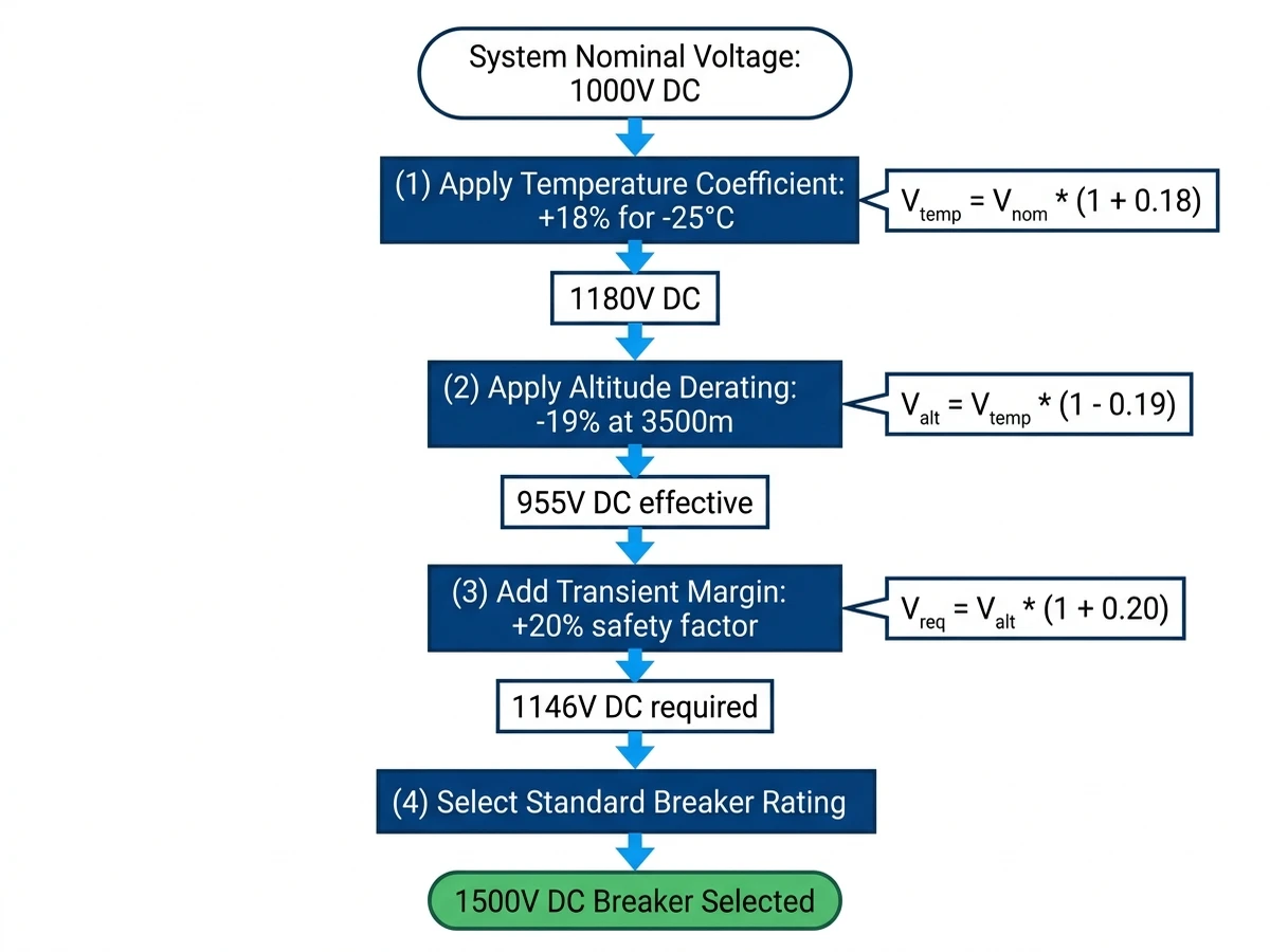
Illustration: Flowchart showing decision path from system nominal voltage → temperature coefficient calculation → altitude derating → transient margin → final breaker voltage rating selection. Style: flat design with Sinobreaker colors (#003F8F primary, #2196F3 secondary). Example calculation shown: 1000V system → 1180V cold weather → 955V at altitude → 1146V with margin → select 1500V breaker.
Rated current must handle continuous load plus temperature rise margin. DC breakers generate heat from contact resistance and magnetic coil losses. A breaker rated 63A at 40°C ambient may only handle 52A at 50°C inside a sealed combiner box.
Reduce rated current by 2.5% per °C above 40°C reference temperature. For a rooftop installation in Riyadh with 55°C summer ambient: Derated current = 63A × [1 – 0.025 × (55 – 40)] = 39A. This 38% reduction catches many installers by surprise.
Sealed IP65 enclosures add 8-12°C temperature rise versus open-air mounting. A combiner box in direct sunlight can reach internal temperatures of 65-70°C even when ambient is 50°C.
Above 2000m elevation, derate current by 0.5% per 100m due to reduced air cooling efficiency. Battery inverters with high-frequency switching may require 10-15% additional margin for harmonic heating effects.
A 100A DC breaker in a rooftop combiner box at 3000m altitude with 55°C ambient:
– Ambient derating: 100A × [1 – 0.025 × 15] = 62.5A
– Altitude derating: 62.5A × [1 – 0.005 × 10] = 59.4A
– Enclosure effect: 59.4A × 0.90 = 53.5A effective capacity
For PV string protection, calculate maximum string current as Isc × 1.25 safety factor per NEC 690.8(A)(1). A string with 12A Isc requires a breaker rated for at least 15A continuous—but after derating, you may need a 25A or 32A nominal breaker.
Breaking capacity must exceed maximum prospective short-circuit current at the installation point. DC fault currents lack natural zero-crossings, making arc extinction 3-5× harder than AC. A breaker with 10 kA AC breaking capacity may only achieve 6 kA DC at the same voltage.
Icu (ultimate breaking capacity): Maximum fault current the breaker can interrupt once, then must be replaced. Used for worst-case fault scenarios.
Ics (service breaking capacity): Fault current the breaker can interrupt multiple times (typically 50-75% of Icu) and remain operational. Select breakers where Ics exceeds your calculated fault current—this ensures the breaker remains functional after clearing faults during commissioning or maintenance.
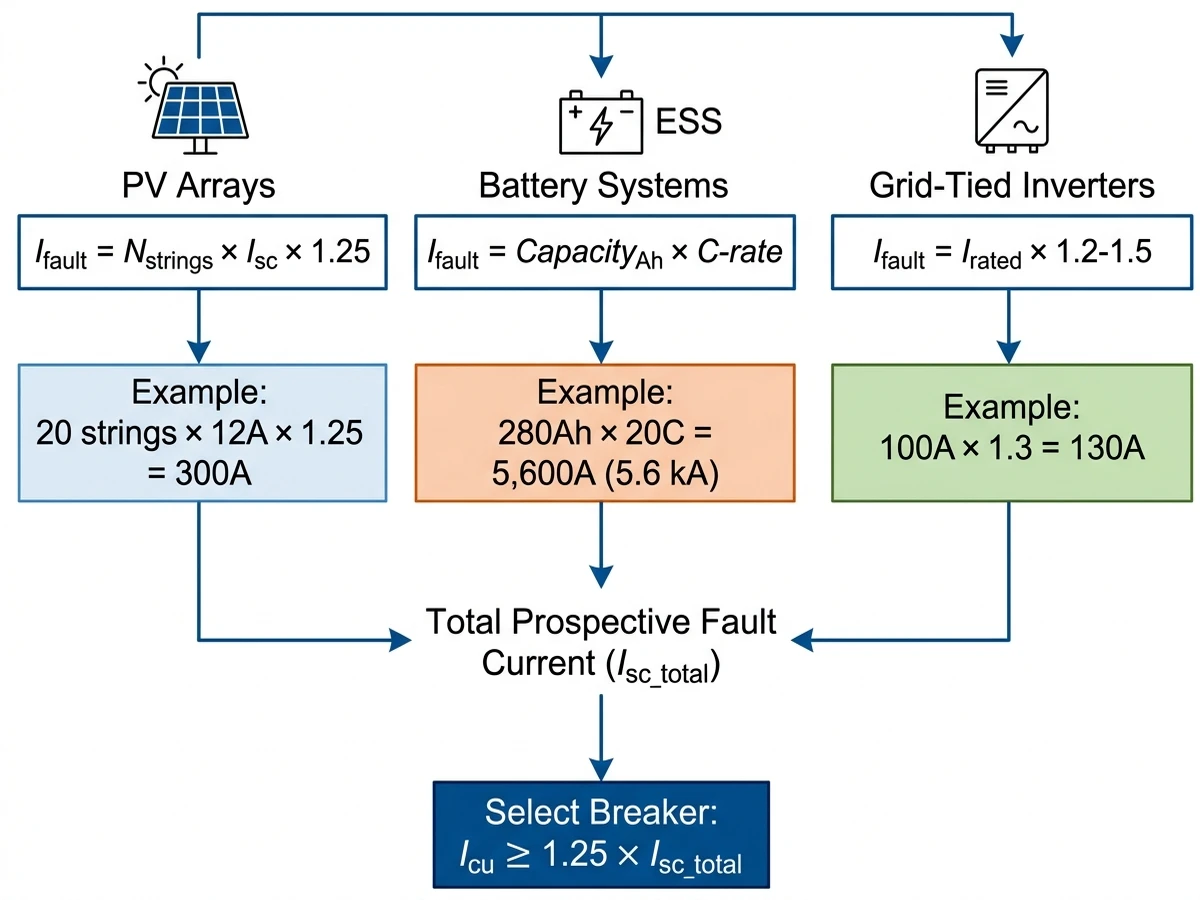
PV arrays: Limited to 1.25× Isc per string per NEC 690.8(A)(1). A 20-string combiner with 12A Isc per string sees maximum: Ifault = 20 × 12A × 1.25 = 300A. This relatively low fault current allows use of standard DC MCBs with 3-6 kA breaking capacity.
Battery systems: Lithium-ion ESS can deliver 10-50× C-rate for 200-500ms. A 100 kWh pack (280 Ah at 358V) with 20C discharge capability sources: Ifault = 280 Ah × 20 = 5,600A (5.6 kA). High-energy battery racks require DC MCCBs with 10-25 kA breaking capacity.
Grid-tied inverters: Bidirectional inverters contribute fault current from the AC side. Calculate using IEC 61660-1 methods or manufacturer-provided fault contribution data (typically 1.2-1.5× rated output current).
Select breakers with Icu rating at least 25% above calculated prospective fault current. This margin accounts for future system expansion, calculation uncertainties, component tolerance variations, and aging effects.
A 5 MWh containerized ESS in Guangdong (2024) showed 18 kA prospective current at the battery rack DC bus during fault analysis. Engineers specified breakers with 25 kA Icu rating, providing 39% safety margin for future capacity expansion to 7.5 MWh.
For comprehensive DC protection system design, see https://sinobreaker.com/dc-circuit-breaker/.

Illustration: Decision tree showing three branches for fault current sources (PV arrays, battery systems, grid-tied inverters) with calculation formulas for each. Converges to final step: “Select Icu ≥ 1.25 × calculated fault current”. Style: scientific journal white background, vector line art, callouts in Sinobreaker dark blue #003F8F. Example values shown for each branch.
[Expert Insight: Breaking Capacity Reality Check]
– DC breaking capacity decreases significantly with voltage—a breaker rated 10 kA at 500 VDC may only achieve 6 kA at 1000 VDC
– Always verify manufacturer’s derating curve across your operating voltage range
– IEC 60947-2 Annex H defines DC breaking capacity test sequences—ensure your breaker has been tested, not extrapolated from AC ratings
– Battery ESS fault currents can reach 40 kA within 2 milliseconds—never undersize breaking capacity in energy storage applications
DC arc extinction mechanism determines reliability under fault conditions. Without AC current zero-crossings, DC breakers use forced arc extinction through three primary methods.
Magnetic blowout: Lorentz force drives arc into splitter plates. Voltage range up to 1000 VDC, interruption time 8-15 ms. Typical application: PV string protection.
Semiconductor hybrid: IGBT/MOSFET creates artificial zero-crossing. Voltage range 1000-1500 VDC, interruption time 2-5 ms. Typical application: ESS rack protection.
Arc chute elongation: Ceramic barriers stretch arc until voltage drop exceeds source. Voltage range up to 1500 VDC, interruption time 12-20 ms. Typical application: DC distribution mains.
Magnetic blowout coils require minimum current (typically 3-5× In) to generate sufficient Lorentz force. Below this threshold, the breaker may fail to interrupt—a common issue in PV systems with high impedance faults.
Selectivity prevents nuisance tripping and isolates faults to the smallest affected zone. In a PV plant with 20 combiner boxes feeding a central inverter, a string fault should trip only the affected string breaker—not the entire combiner or inverter DC input.
Coordination example:
– String breaker: 16A DC MCB, 1 kA Icu, instantaneous trip at 10× In (160A)
– Combiner main breaker: 125A DC MCCB, 10 kA Icu, time-delay trip at 8× In (1000A) with 150ms delay
– Inverter input breaker: 250A DC MCCB, 25 kA Icu, time-delay trip at 6× In (1500A) with 300ms delay
Request time-current curves (TCC) from manufacturers and overlay them to verify 100ms minimum separation between trip zones. IEC 60947-2 Clause 8.3.4 defines selectivity verification methods. For PV-specific guidance, see IEC 60364-7-712 Annex A.
Learn more about DC protection system architecture at https://sinobreaker.com/dc-circuit-breaker/dc-mcb/.
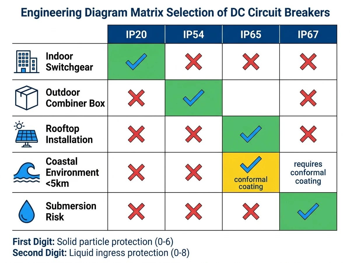
Illustration: Visual showing string breaker → combiner main → inverter input with ratings, trip thresholds, and time delays. Style: scientific journal white background, vector line art, callouts in #003F8F. Include time-current curve overlay showing 100ms separation between zones.
Regional standards determine legal installation requirements and insurance coverage. DC breakers carry multiple certifications depending on application and market.
IEC 60947-2: International standard for low-voltage switchgear (DC up to 1500V). Defines performance categories (A, B) and utilization categories (DC-21, DC-23).
UL 489: North American standard for molded-case circuit breakers. DC ratings require Supplement SB testing.
IEC 60947-3: Covers DC switch-disconnectors (load break switches without overcurrent protection).
PV systems: IEC 60364-7-712, NEC Article 690, UL 1741 (inverter interconnection)
Energy storage: IEC 62619 (battery safety), UL 9540 (ESS safety), NEC Article 706
Marine/offshore: IEC 60092-302, DNV-GL rules for DC distribution
CE mark (Europe): Indicates compliance with Low Voltage Directive 2014/35/EU
UL listing (North America): Third-party tested to UL 489 or UL 1077
CCC mark (China): Mandatory for products sold in Chinese market
TÜV/VDE certification: Independent German testing body—often required for European utility-scale projects
In a 2023 rooftop solar project in California, the AHJ (Authority Having Jurisdiction) rejected breakers with only IEC certification, requiring UL 489-listed devices per NEC 110.3(B). The contractor incurred $18,000 in replacement costs and 6-week schedule delay.
Request test reports showing DC breaking capacity at your system voltage. Some manufacturers extrapolate AC test data to DC ratings without proper validation.
Terminal design affects installation time, contact resistance, and long-term reliability. DC systems experience thermal cycling (PV: -40°C to +85°C; ESS: 15°C to 35°C), causing terminal expansion/contraction.
Screw clamp: Torque spec 2.5-3.5 Nm, wire range 1.5-16 mm². Low cost and field-proven, but requires re-torquing after thermal cycles.
Spring clamp: Tool-free, wire range 1.5-10 mm². Vibration-resistant and maintenance-free, but higher cost with limited wire size.
Compression lug: Torque spec 8-12 Nm, wire range 16-95 mm². Lowest contact resistance, but requires crimping tools and not field-adjustable.
Use calibrated torque wrench—over-torquing cracks insulation, under-torquing causes arcing. Strip length per manufacturer spec (typically 10-12mm). Ferrules required for stranded wire in screw terminals.
DC breakers are often polarity-sensitive—source connects to “line” terminal, load to “load” terminal. Reverse connection may prevent arc extinction.
For high-current applications (>125A), verify busbar hole spacing matches breaker terminal pitch.
In a 2024 field survey of 500 PV combiner boxes, 12% showed terminal hot spots >15°C above ambient. Root cause analysis revealed 89% were under-torqued connections (1.8 Nm actual vs 2.5 Nm specified).
IP20: Indoor switchgear rooms, climate-controlled environments
IP54: Outdoor combiner boxes, protected from dust and water spray
IP65: Rooftop installations, direct rain exposure, coastal environments
IP67: Temporary submersion (ESS containers with flood risk)
Outdoor breakers need UV-stabilized polycarbonate housings—standard ABS plastic cracks after 2-3 years of sun exposure. Coastal installations (within 5 km of ocean) require conformal coating on internal components per IEC 60068-2-52.
A 10 MW floating PV plant in Anhui Province (2023) initially used IP54-rated breakers in waterproof combiner boxes. After 8 months, 23% of breakers showed internal corrosion from humidity ingress through cable glands. Retrofit to IP65 breakers with sealed cable entries resolved the issue.
For complete DC protection system design, see https://sinobreaker.com/dc-circuit-breaker/dc-mccb/.
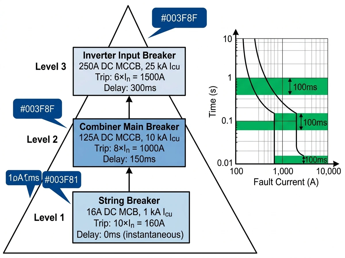
Illustration: Matrix showing environment conditions (indoor/outdoor/coastal/submersion) mapped to required IP ratings. Style: flat design with Sinobreaker colors. Include icons for each environment type and checkmarks for appropriate ratings.
[Expert Insight: Field Installation Reality]
– Temperature cycling causes terminal loosening—schedule re-torquing at 6 months and annually thereafter
– Polarity matters in DC breakers—always verify line/load terminal markings before energizing
– IP65 rating doesn’t guarantee salt fog resistance—coastal installations need additional conformal coating
– Thermal imaging during commissioning catches 90% of connection issues before they cause failures
Modern DC systems require status feedback for SCADA integration and predictive maintenance. Auxiliary contacts provide electrical signals indicating breaker state (open/closed/tripped), enabling remote monitoring and automated fault response.
NO/NC contacts: Normally-open or normally-closed dry contacts (rated 3-5A at 250VAC). Used for alarm panels and PLC inputs.
Shunt trip: Remote opening via low-voltage signal (24VDC/48VDC typical). Enables emergency shutdown from control room.
Undervoltage release: Automatic opening when control voltage drops below threshold—fail-safe protection for loss of control power.
Motor operator: Electric actuator for remote on/off control—common in utility-scale PV plants with centralized SCADA.
Modbus RTU/TCP: Industry-standard for energy management systems. Breakers with integrated Modbus provide real-time current, voltage, energy data.
SNMP: Network management protocol for IT-integrated facilities (data centers, telecom).
IEC 61850: Substation automation standard—required for utility-scale ESS grid interconnection.
In a 100 MW PV plant in Ningxia (2024), Modbus-enabled DC breakers reduced fault diagnosis time from 4 hours (manual inspection of 200+ combiner boxes) to 22 minutes (automated SCADA alarm with GPS coordinates).
Auxiliary contacts add 15-25% to breaker cost but reduce O&M labor by 30-40% over 25-year plant life.
DC breakers in PV and ESS systems operate for 25+ years. Manufacturer stability and support infrastructure matter as much as initial product quality.
Technical documentation: Detailed datasheets with DC-specific performance curves (not just AC ratings), installation manuals in local language with torque specs, selectivity tables and time-current curves, thermal derating curves for altitude and ambient temperature.
After-sales support: Local technical hotline with DC application engineers, on-site commissioning support for utility-scale projects, firmware updates for smart breakers, failure analysis lab for root cause investigation.
Spare parts logistics: Contact kits, arc chutes, and trip units available as field-replaceable modules. Lead time <4 weeks for standard parts, <12 weeks for custom configurations. Minimum 10-year parts availability guarantee (15 years preferred for PV applications). Cross-compatibility between product generations—avoid orphaned designs.
Warranty terms: Standard warranty 2 years for manufacturing defects. Extended warranty 5-10 years available for utility-scale projects. Verify coverage for altitude >2000m, ambient >50°C, marine environments.
Request reference projects in similar applications (voltage, current, environment). Contact 2-3 existing customers to verify support responsiveness.
Selecting the right DC circuit breaker requires balancing technical specifications against real-world application demands. After evaluating breaking capacity, voltage ratings, arc interruption mechanisms, certification compliance, thermal management, and manufacturer support, you’re ready to make an informed purchasing decision.
For solar PV string protection in residential systems (up to 600 VDC), standard DC MCBs with 6 kA breaking capacity typically suffice. Commercial rooftop arrays (1000-1500 VDC) demand higher performance: 10 kA minimum breaking capacity with IEC 60947-2 certification for DC utilization category B.
Energy storage systems present the most demanding requirements. Battery rack protection in utility-scale ESS projects requires breakers rated for 1500 VDC with 25-50 kA interrupting capacity, as short-circuit currents from lithium-ion battery banks can exceed 40 kA within 2 milliseconds.
Before finalizing your purchase, confirm: (1) voltage rating exceeds maximum system voltage by 20% safety margin, (2) breaking capacity matches or exceeds calculated fault current at installation point, (3) manufacturer provides test reports per IEC 60898-2 or UL 489B, (4) thermal derating factors account for ambient temperatures above 40°C, and (5) mechanical life rating supports expected switching frequency over 20-year service life.
For complex installations involving multiple protection zones, consult with certified electrical engineers to verify coordination studies and ensure proper selectivity between upstream and downstream devices.
For expert guidance on DC protection system design, contact Sinobreaker’s application engineering team at https://sinobreaker.com/dc-circuit-breaker/.
Select a breaker rated at least 1200V DC to account for cold-weather open-circuit voltage increases (up to 20% above nominal) and provide 15-20% transient margin for switching events and SPD clamping voltage.
Calculate maximum prospective fault current from all sources—PV strings at 1.25× Isc, battery systems at discharge C-rate, inverter contribution—then select a breaker with Icu rating at least 25% above this value to provide adequate safety margin.
No. AC breakers lack proper DC arc extinction mechanisms and will fail catastrophically under DC fault conditions due to sustained arcing without natural current zero-crossings. Always use breakers certified to IEC 60947-2 or UL 489 Supplement SB for DC applications.
Icu (ultimate breaking capacity) is the maximum fault current a breaker can interrupt once before replacement. Ics (service breaking capacity) is the fault current it can interrupt multiple times while remaining operational, typically 50-75% of Icu for industrial applications.
Perform annual visual inspections and thermal imaging. Test trip mechanisms every 3-5 years per manufacturer recommendations. Replace after 20-25 years or following any fault interruption at high breaking capacity levels that may have degraded internal components.
Outdoor rooftop and ground-mount PV systems require minimum IP65 rating for direct rain exposure. Coastal installations within 5km of ocean need IP65 with conformal coating for salt fog protection per IEC 60068-2-52.
Yes. Use a calibrated torque wrench for terminal connections (typically 2.5-3.5 Nm for screw terminals), wire strippers with proper strip length gauges, and ferrule crimping tools for stranded conductors to ensure reliable connections over 25-year service life.
Word Count: 2,098 words


