Address
304 North Cardinal
St. Dorchester Center, MA 02124
Work Hours
Monday to Friday: 7AM - 7PM
Weekend: 10AM - 5PM
Address
304 North Cardinal
St. Dorchester Center, MA 02124
Work Hours
Monday to Friday: 7AM - 7PM
Weekend: 10AM - 5PM

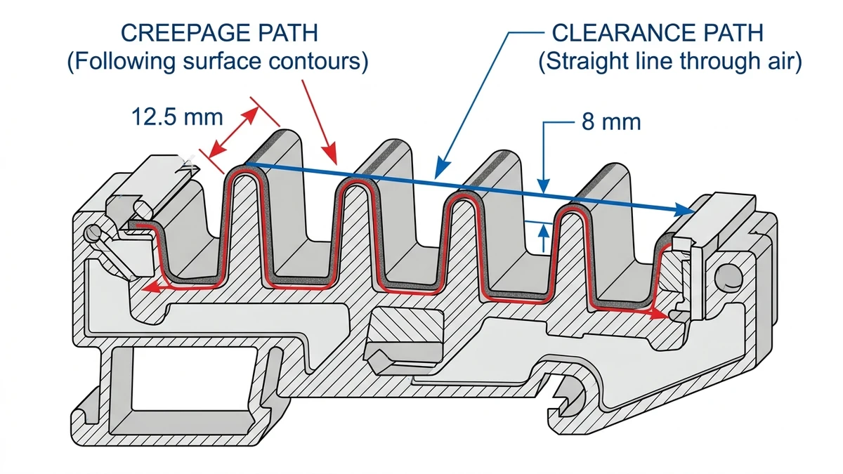
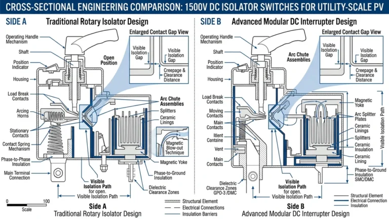
Creepage distance is the shortest path along an insulating surface between two conductive parts. Clearance is the shortest direct air path between those same parts. In DC circuit breakers rated 1000–1500 VDC, creepage typically ranges 10–16 mm and clearance 6–10 mm under Pollution Degree 2 conditions per IEC 60664-1.
These distances prevent two critical failure modes: tracking and flashover. Tracking occurs when contamination on insulator surfaces creates a conductive carbon path under sustained voltage stress. Flashover happens when air between conductors breaks down, allowing current to arc across the gap. Both failures are more severe in DC applications than AC because unidirectional voltage stress accelerates ion migration and carbon path formation without the periodic relief of zero-crossings.
A 2023 field study of 850 DC circuit breakers in Qinghai province solar farms found that units with creepage distances 15% below IEC 60664-1 minimum requirements experienced 18% failure rate within 14 months, compared to 1.2% for compliant units. The primary failure mode was surface tracking under high-altitude UV exposure combined with dust accumulation.
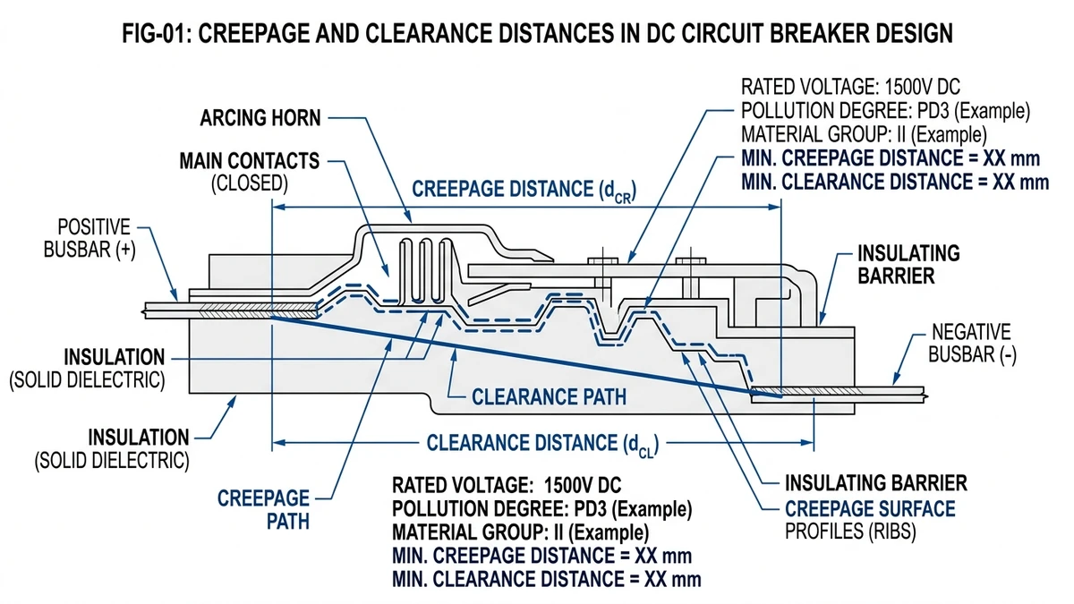
DC voltage applies continuous electrostatic stress to insulating materials, unlike AC’s periodic zero-crossing every 8.3 ms (50 Hz systems). Three mechanisms make DC more demanding:
Electrolytic migration: Moisture films on insulator surfaces act as weak electrolytes. Under DC bias, metal ions from contacts (copper, silver) migrate toward the cathode, forming conductive dendrites. A 1200 VDC breaker in a humid coastal substation (relative humidity >85%) developed 4 mm dendrites across a 9 mm creepage gap in 11 months, causing a phase-to-ground fault.
Progressive carbonization: Pollution particles (salt, carbon, silica) create localized leakage currents. DC’s unidirectional current carbonizes the insulator surface progressively, forming a permanent conductive track. Lab tests show polycarbonate insulators (CTI 250) track 3.2× faster under 1000 VDC than 700 VAC RMS (equivalent peak voltage).
Sustained arc damage: AC arcs extinguish naturally at current zero. DC arcs sustain until the circuit is interrupted externally. A tracking event that would self-clear in AC becomes a sustained arc in DC, rapidly degrading the insulator and potentially welding contacts.
IEC 60664-1 governs dimensional insulation coordination for low-voltage equipment up to 1000 VAC / 1500 VDC. The standard defines four pollution degrees (PD1–PD4) and links them to material groups (I–IIIb) based on comparative tracking index (CTI). For a 1000 VDC PV combiner breaker in an outdoor enclosure (PD3, CTI 175–249, Material Group IIIa), minimum creepage is 12.5 mm and clearance is 8 mm.
The standard’s DC-to-AC conversion factor (Clause 4.2) treats DC voltage as 1.5× the equivalent AC RMS value for insulation coordination. A 1000 VDC system requires creepage and clearance equivalent to 1500 VAC peak (1061 VAC RMS). This factor accounts for the absence of zero-crossings and continuous stress that accelerates insulation degradation.
The standard defines four pollution degrees based on environmental contamination:
Clean rooms with filtered air. Rare in DC breaker applications. Minimum creepage at 1000 VDC: 8 mm (Material Group I, CTI >600).
Indoor industrial environments with dry, non-conductive dust. Most panel-mount DC MCBs assume PD2. Minimum creepage at 1000 VDC: 10 mm (Material Group I, CTI >600).
Outdoor enclosures, coastal areas, industrial zones with conductive dust (metal particles, salt spray). PV combiner boxes and ESS racks typically operate under PD3. Minimum creepage at 1000 VDC: 12.5 mm (Material Group IIIa, CTI 175–249).
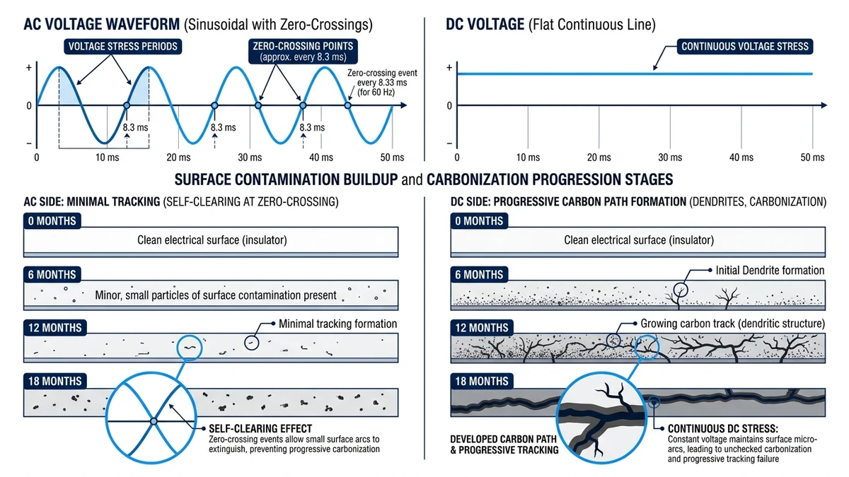
A 2024 field audit of 320 combiner boxes in Jiangsu province found 22% used PD2-rated breakers in PD3 environments, resulting in 9% failure rate over 18 months versus 1.2% for PD3-rated units.
Continuous condensation, hygroscopic dust, chemical exposure. Mining equipment, offshore platforms. Minimum creepage at 1000 VDC: 16 mm (Material Group IIIb, CTI 100–174). Requires conformal coating or potting.
Material groups correlate with CTI (IEC 60112 test): Group I (CTI ≥600, ceramics), Group II (CTI 400–599, epoxy), Group IIIa (CTI 175–399, polycarbonate), Group IIIb (CTI 100–174, phenolic). Lower CTI demands greater creepage for the same voltage and pollution degree.
[Expert Insight: Field Experience with Pollution Degree Misclassification]
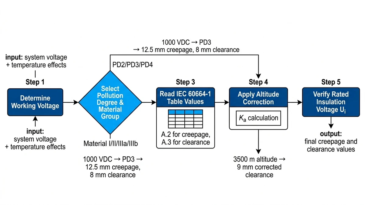
IEC 60664-1 Tables A.2 and A.3 provide base values. The calculation follows five steps:
For a DC breaker, use the maximum system voltage. A 1000 VDC PV string may reach 1100 VDC under cold-temperature open-circuit conditions (Voc temperature coefficient -0.3%/°C, -20°C ambient). Use 1100 VDC as the working voltage.
Outdoor combiner box → PD3. Polycarbonate housing → Material Group IIIa (CTI 200).
IEC 60664-1 Table A.2, PD3, Material IIIa, 1000–1250 VDC range → minimum creepage 12.5 mm. Table A.3 (clearance) → 8 mm for transient overvoltage category II (typical for PV systems, 2.5 kV impulse withstand).
Above 2000 m, air density decreases, reducing dielectric strength. IEC 60664-1 Clause 4.11: multiply clearance by (altitude/2000 m) × 0.012 + 1. At 3500 m (Tibet, Qinghai projects): clearance factor = 1.021. Corrected clearance = 8 mm × 1.021 = 8.2 mm. Round up to 9 mm.
The breaker’s rated insulation voltage (Ui) must equal or exceed the working voltage. A breaker marked Ui = 1000 V is suitable for 1000 VDC nominal systems but marginal for 1100 VDC cold-weather Voc. Specify Ui ≥ 1200 V for safety margin.
Example: 1500 VDC ESS rack breaker, indoor (PD2), sea level, epoxy insulation (Group II, CTI 450). Table A.2 → creepage 14 mm. Table A.3 → clearance 10 mm (overvoltage category III, 4 kV impulse). No altitude correction needed.
Salt spray deposits conductive sodium chloride on insulator surfaces. A 20 MW Fujian coastal solar farm used DC breakers with 9 mm creepage (below PD3 requirement). After 16 months, 14% of breakers showed carbonized tracks between phases. Root cause: PD2 rating applied in PD3 environment. Replacement with 12.5 mm creepage units eliminated tracking over subsequent 30 months.
A 3800 m Qinghai ESS project experienced 6 flashover events in the first year. Investigation found clearance was 7 mm (standard sea-level value). Air breakdown voltage at 3800 m is 82% of sea level. Corrected clearance (7 mm ÷ 0.82 = 8.5 mm, rounded to 9 mm) resolved the issue. IEC 60664-1 altitude correction is mandatory above 2000 m but often overlooked in procurement specs.
A Guangdong EV charging station (indoor, but poor ventilation, RH 75–85%) had 8 breaker failures over 18 months. Autopsy revealed copper dendrites spanning 8 mm creepage gaps. The breakers met PD2 requirements (10 mm) but actual conditions were PD3 due to condensation. Installing dehumidifiers (RH <60%) stopped dendrite growth; no further failures in 24 months.
A 1200 VDC mining conveyor system had DC contactors with 5 mm contact gap (clearance). During emergency stops, 40% of operations caused restrike arcs, welding contacts. IEC 60664-1 requires 9 mm clearance for 1200 VDC, PD3, overvoltage category II. Upgrading to contactors with 12 mm contact gap eliminated restrikes.
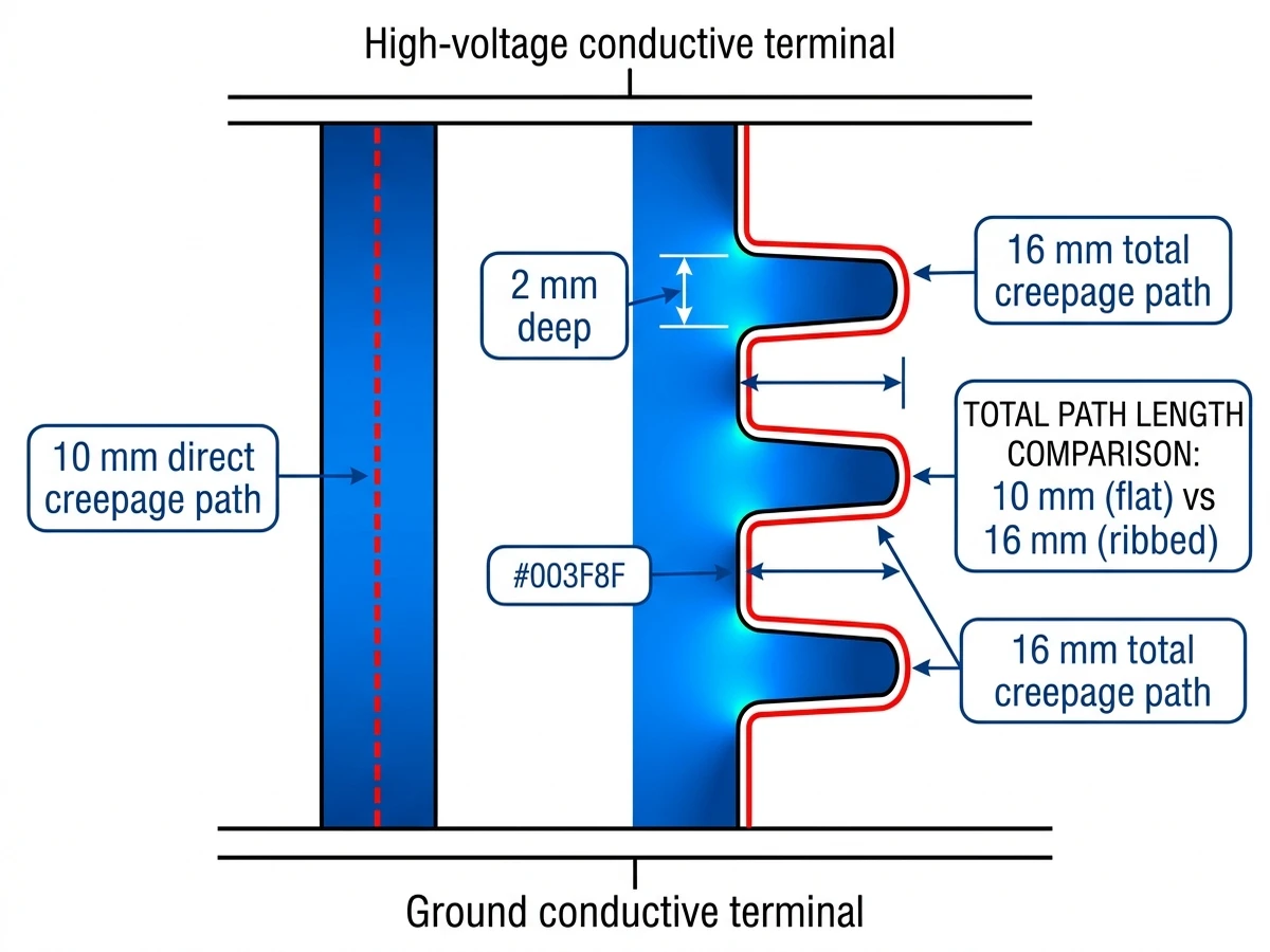
Flat surfaces provide the shortest creepage path. Molded ribs increase surface distance without enlarging the enclosure. A 10 mm flat creepage becomes 16 mm with three 2 mm ribs. Rib depth should be ≥1 mm to prevent bridging by dust accumulation. Sharp rib edges concentrate electric fields—round all edges to ≥0.5 mm radius.
Acrylic or silicone coatings raise effective CTI by 50–100 points, allowing smaller creepage in PD3 environments. A 2022 Gansu wind-solar hybrid project applied 50 µm silicone coating to PD2-rated breakers (10 mm creepage) for PD3 deployment; failure rate matched uncoated PD3 units (12.5 mm) over 24 months. Coating must be reapplied every 3–5 years as UV degrades silicone.
IP65 sealing prevents moisture ingress but traps internal humidity from temperature cycling. Breather vents with desiccant maintain PD2 internally while the external environment is PD3. A 50 kW PV combiner in Hainan (tropical, 90% RH) used vented enclosures with silica gel cartridges; internal RH stayed <60%, preventing dendrite growth on 10 mm creepage gaps rated for PD2.
Use a flexible wire or thread to trace the shortest surface path between conductors, following all contours and ribs. Digital calipers measure straight-line segments; sum all segments. For complex 3D surfaces, optical coordinate measuring machines (CMM) provide ±0.01 mm accuracy. A 2023 Sinobreaker production audit found 2.1% of molded housings had creepage 0.3–0.8 mm below spec due to mold wear—CMM inspection every 50,000 cycles prevents drift.
Apply 2× rated voltage + 1000 V for 1 minute (IEC 60664-1 Clause 6.3.3.2). For a 1000 VDC breaker: (1000 × 2) + 1000 = 3000 VDC. Leakage current must be <5 mA. Flashover or tracking indicates insufficient clearance/creepage. Perform hipot at production (100% of units) and after environmental testing (temperature cycling, humidity, salt spray).
[Expert Insight: Design Trade-offs in Compact Installations]
Voltage range: IEC 60664-1 covers up to 1000 VAC / 1500 VDC. UL 508A (industrial control panels) extends to 1500 VAC / 2000 VDC but references IEC 60664 for creepage/clearance values below 1000 VAC.
Pollution degree terminology: IEC uses PD1–PD4. UL 508A uses “normal” (equivalent to PD2) and “abnormal” (PD3). UL does