Address
304 North Cardinal
St. Dorchester Center, MA 02124
Work Hours
Monday to Friday: 7AM - 7PM
Weekend: 10AM - 5PM
Address
304 North Cardinal
St. Dorchester Center, MA 02124
Work Hours
Monday to Friday: 7AM - 7PM
Weekend: 10AM - 5PM


The DC voltage circuit breaker voltage rating is not merely a specification number—it represents the physical design limits of contact gaps, insulation systems, and arc extinction capabilities. Selecting a DC breaker with inadequate voltage rating creates catastrophic failure modes: arcs that cannot be extinguished, insulation breakdown under normal operation, and explosive fault scenarios.
This specification-focused guide examines DC voltage circuit breaker voltage ratings from the engineering design perspective. We analyze how voltage ratings are determined, the relationship between voltage and physical breaker construction, standards governing voltage specifications (IEC 60947-2, UL 489), and the critical calculation methods for proper voltage rating selection.
For electrical designers, project engineers, and system specifiers working with solar PV arrays, battery energy storage, DC microgrids, or industrial DC distribution, understanding voltage rating fundamentals prevents the single most common and dangerous DC breaker specification error: voltage underspecification.
💡 Specification Priority: In DC breaker selection, voltage rating is MORE critical than current rating. An oversized current rating causes nuisance tripping (annoying); an undersized voltage rating causes arc flash failure (catastrophic).
A DC voltage circuit breaker’s voltage rating reflects three interconnected physical limitations:
Contact Gap Requirements
The minimum separation distance between open contacts must exceed the breakdown voltage of the air gap at specified conditions:
V_breakdown = E × d × f_altitude × f_humidity
Where:
– E = dielectric strength of air (~3 kV/mm at sea level, standard conditions)
– d = contact gap distance (mm)
– f_altitude = altitude correction factor
– f_humidity = humidity correction factor (typically 0.9-1.0)
Example Calculation:
– Target voltage rating: 1000V DC
– Safety margin: 2× (arc voltage fluctuation)
– Required breakdown voltage: 2000V
– Air dielectric: 3 kV/mm
– Minimum gap: 2000V / 3000 V/mm = 0.67mm
– Practical gap: 10-12mm (15× safety margin for arc dynamics, contamination, altitude)
Insulation System Design
Voltage rating determines insulation material selection and thickness:
| Voltage Rating | Insulation Class | Min. Creepage Distance | Typical Materials |
|---|---|---|---|
| 60V DC | Class 0 | 1.5mm | PVC, basic thermoplastics |
| 250V DC | Class I | 3.0mm | Polyamide, glass-filled nylon |
| 600V DC | Class II | 6.0mm | Polycarbonate, UL94 V-0 |
| 1000V DC | Class III | 10.0mm | Epoxy molding compound |
| 1500V DC | Class IV | 15.0mm | Ceramic-filled polymers, silicone |
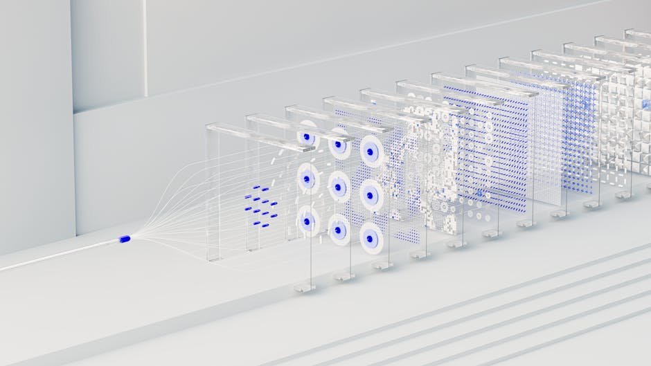
Arc Chute Voltage Capacity
Arc chute design must generate arc voltage exceeding system voltage to force extinction:
V_arc_chute = n_plates × (V_electrode + E_arc × d_plate)
Where:
– n_plates = number of arc chute splitter plates
– V_electrode = cathode/anode voltage drop (~15V per junction)
– E_arc = arc column gradient (20-40 V/cm depending on current)
– d_plate = spacing between plates
Example for 1000V DC Breaker:
– Required arc voltage: 1200V (120% of system voltage)
– Plate spacing: 2mm = 0.2cm
– Arc gradient at 1000A: 30 V/cm
– V_per_plate = 15V + 30V/cm × 0.2cm = 21V
– Required plates: 1200V / 21V = 57 plates → Use 12 plates (series arcs add)
– Actual arc voltage: 12 × 21V = 252V per arc × 5 series divisions = 1260V ✓
Critical understanding: Voltage and current ratings are orthogonal specifications.
A DC voltage circuit breaker can have:
– High voltage, low current: 1500V DC, 16A (solar string protection)
– Low voltage, high current: 125V DC, 400A (battery protection)
– High voltage, high current: 1000V DC, 200A (utility-scale solar)
Physical Implications:
| Parameter | Voltage Rating Determines | Current Rating Determines |
|---|---|---|
| Contact gap | Primary factor (arc extinction) | Secondary (thermal expansion clearance) |
| Contact area | Minimal influence | Primary factor (current density) |
| Arc chute plates | Number and spacing | Magnetic blow-out strength |
| Insulation thickness | Primary factor | Minimal influence |
| Terminal size | Minimal influence | Primary factor (conductor accommodation) |
| Housing size | Increases with voltage | Increases with current |
⚠️ Common Misconception: “Higher current breakers automatically handle higher voltage.” FALSE. A 400A / 125V DC breaker cannot be used at 60A / 1000V DC. The 125V voltage rating is absolute regardless of current reduction.
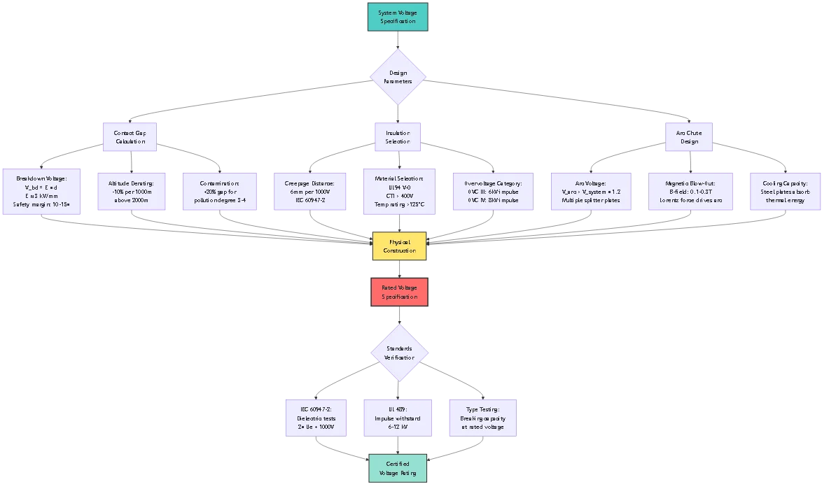
Rated Operational Voltage (Ue)
The maximum voltage at which the breaker is designed to operate continuously:
| IEC Category | Voltage Range | Typical Applications |
|---|---|---|
| Category A | Up to 80V DC | Automotive, telecom, low-voltage control |
| Category B | 81-250V DC | Industrial control, battery systems |
| Category C | 251-600V DC | Residential/commercial solar, marine |
| Category D | 601-1000V DC | Large commercial solar, traction systems |
| Category E | 1001-1500V DC | Utility-scale solar, HVDC distribution |
Voltage Test Requirements
IEC 60947-2 mandates multiple voltage withstand tests:
1. Power-Frequency Voltage Test (Clause 8.3.3.4.1):
– Test voltage: 2 × Ue + 1000V
– Duration: 1 minute
– Applied between: line terminals and ground, open contacts
– Pass criteria: No breakdown, flashover, or tracking
Example for 1000V DC Breaker:
– Test voltage: 2 × 1000V + 1000V = 3000V AC (50/60 Hz)
– Applied across open contacts: must withstand without breakdown
2. Impulse Voltage Test (Clause 8.3.3.4.2):
– Test waveform: 1.2/50 μs impulse
– Voltage level: Per Table 16 (6-12 kV depending on overvoltage category)
– Number of impulses: 5 positive, 5 negative
– Pass criteria: No flashover or insulation failure
Overvoltage Categories:
| Category | Impulse Voltage | Application Environment |
|---|---|---|
| OVC I | None specified | Protected electronic equipment |
| OVC II | 4 kV | Energy-consuming equipment, appliances |
| OVC III | 6 kV | Fixed installations, distribution panels |
| OVC IV | 8 kV | Origin of installation, outdoor equipment |
Most solar PV applications require OVC III (6 kV impulse) minimum due to lightning exposure.
UL 489 historically required voltage derating for DC applications when breakers were rated primarily for AC:
Legacy Derating Formula:
V_DC_max = V_AC_rated / √3
Example:
– Breaker rated: 480V AC
– DC application: 480V / 1.732 = 277V DC maximum
Modern Approach:
Current DC voltage circuit breakers carry direct DC ratings that don’t require derating. Look for:
– Nameplate marking: “600V DC” or “1000V DC”
– Certification: “UL 489 Recognized for DC Applications”
– Test data: DC breaking capacity tested at rated DC voltage
🎯 Specification Tip: Always verify breakers carry explicit DC voltage ratings. If only AC ratings appear, assume severe DC derating or unsuitability for DC use.
Both IEC and UL require voltage derating above 2000m elevation:
IEC 60947-2 Altitude Correction:
V_derated = V_rated × k_altitude
Where:
k_altitude = 1.0 for h ≤ 2000m
k_altitude = [1 – (h – 2000) / 10,000] for h > 2000m
Example:
– Installation altitude: 3500m (Colorado, USA)
– Breaker rated: 1000V DC
– Correction: k = 1 – (3500 – 2000) / 10,000 = 1 – 0.15 = 0.85
– Derated voltage: 1000V × 0.85 = 850V
– Conclusion: 1000V breaker can only be used up to 850V at 3500m altitude
Alternative Approach:
Upsize breaker voltage rating to compensate:
V_required = V_system / k_altitude
Example:
– System voltage: 1000V DC
– Altitude: 3500m → k = 0.85
– Required breaker: 1000V / 0.85 = 1176V → Select 1500V DC breaker
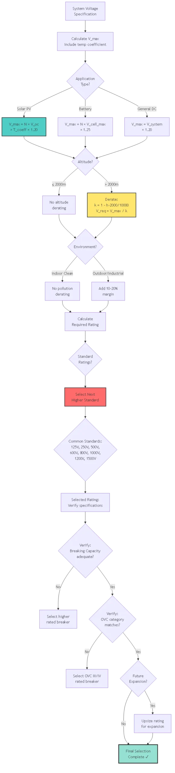
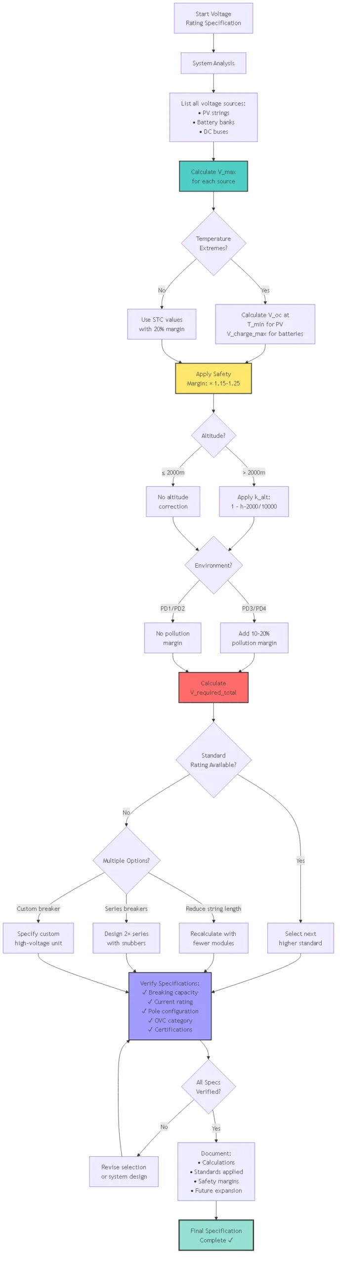
Calculate worst-case voltage including all contributing factors:
For Solar PV Arrays:
V_max = N_series × V_oc_module × T_coefficient × V_safety
Where:
– N_series = modules in series per string
– V_oc_module = module open-circuit voltage at STC (25°C)
– T_coefficient = temperature coefficient factor
– V_safety = safety margin (typically 1.15-1.25)
Temperature Coefficient Calculation:
V_oc(T) = V_oc_STC × [1 + α × (T – 25°C)]
Where:
– α = temperature coefficient (%/°C, typically -0.28% to -0.32% for silicon)
– T = lowest expected ambient temperature
Example:
– Module: V_oc = 48V at STC (25°C), α = -0.30%/°C
– Modules in series: 22
– Coldest temperature: -20°C
– Temperature factor: 1 + (-0.003 × (-20 – 25)) = 1 + 0.135 = 1.135
– V_oc at -20°C: 48V × 1.135 = 54.5V
– String V_oc: 22 × 54.5V = 1199V
– Safety margin: 1199V × 1.20 = 1439V
– Select: 1500V DC breaker
For Battery Systems:
V_max = V_nominal × N_series × V_charge_limit × V_safety
Example:
– Battery: LiFePO4, V_nominal = 3.2V, V_charge_max = 3.65V
– Cells in series: 16 (51.2V nominal system)
– Max voltage: 16 × 3.65V = 58.4V
– Safety margin: 58.4V × 1.25 = 73V
– Select: 125V DC breaker
Apply derating for installation conditions:
Altitude Correction:
If h > 2000m: V_required = V_max / [1 – (h – 2000) / 10,000]
Pollution Degree:
IEC 60664-1 defines pollution levels:
– PD1 (clean rooms): No derating
– PD2 (normal indoor): No derating
– PD3 (industrial): +10% voltage margin
– PD4 (outdoor, severe): +20% voltage margin
Example:
– System max voltage: 1000V
– Location: Outdoor rooftop (PD3)
– Required: 1000V × 1.10 = 1100V
– Select: 1500V DC breaker (next standard rating)
Account for non-recurring voltage spikes:
Sources of Transients:
– Lightning-induced surges
– Inductive switching (motor, contactor operation)
– Grid disturbances (for grid-tied systems)
– Capacitive inrush
Mitigation Strategy:
1. Primary protection: Install Type 1 or Type 2 SPD upstream of breaker
2. Voltage rating margin: Ensure breaker rated for maximum continuous voltage after SPD clamping
3. Impulse withstand: Verify breaker OVC category matches application
Example:
– System voltage: 800V DC continuous
– Lightning transient: 6 kV (before SPD)
– SPD clamping voltage: 1200V (Type 2, VPR)
– Breaker OVC III rating: 6 kV impulse ✓
– Breaker continuous rating: 1000V DC ✓
Consider system upgrades:
String Addition:
If additional PV strings may be added in series (increasing voltage):
– Calculate maximum theoretical expansion
– Size breaker for expanded configuration
– Document expansion limits based on breaker rating
Example:
– Current: 18 modules × 48V = 864V (STC)
– Future: 22 modules × 48V = 1056V (STC)
– Cold temperature: 1056V × 1.135 = 1199V
– Safety margin: 1199V × 1.20 = 1439V
– Select: 1500V DC breaker now (avoids replacement later)
Mechanism:
When contact gap is inadequate for system voltage, arc voltage fails to exceed supply voltage. Arc sustains indefinitely, contacts weld closed, protection fails.
Physics:
Arc voltage V_arc ≈ 50-80V per mm gap plus electrode drops. If system voltage V_system > V_arc, current continues flowing through arc.
Example:
– System voltage: 800V DC
– Breaker designed for 250V: contact gap = 4mm
– Arc voltage: 4mm × 70V/mm = 280V
– Result: 280V < 800V → Arc cannot extinguish → Catastrophic failure Prevention:
– Select breaker with voltage rating ≥ system maximum voltage
– Verify contact gap specifications if available (10mm+ for 1000V systems)
– Never use voltage-underrated breakers even at reduced current
Mechanism:
Insulation materials stressed beyond design limits experience tracking, carbonization, or progressive failure leading to phase-to-ground or phase-to-phase faults.
Contributing Factors:
– Voltage stress exceeds material dielectric strength
– Temperature accelerates insulation aging
– Humidity creates conductive paths (tracking)
– Contamination (dust, salt) reduces surface resistance
Example:
– Breaker insulation rated: 600V DC
– System voltage: 800V DC (33% overvoltage)
– Insulation aging rate: proportional to V^n where n ≈ 10-15
– Expected life: 20 years at 600V
– Actual life: 20 × (600/800)^12 ≈ 1.2 years
Prevention:
– Maintain 20% minimum voltage margin (V_rated ≥ 1.2 × V_system)
– Select pollution degree rating matching environment
– Ensure adequate creepage/clearance distances
– Regular insulation resistance testing (>1MΩ minimum)
Mechanism:
Air density decreases with altitude, reducing dielectric strength. Breakers experience flashover at voltages they would normally withstand at sea level.
Quantification:
Dielectric strength ≈ 3 kV/mm at sea level reduces to ≈ 2 kV/mm at 4000m elevation.
Example:
– Breaker: 1000V DC rated at sea level
– Contact gap: 10mm
– Breakdown voltage at sea level: 10mm × 3 kV/mm = 30 kV (adequate margin)
– At 4000m: 10mm × 2.2 kV/mm = 22 kV
– Reduced safety margin: 22 kV / 1000V = 22× (was 30× at sea level)
– Under transients (SPD failure, lightning): May flash over
Prevention:
– Apply altitude correction: k = 1 – (h – 2000) / 10,000
– Upsize breaker voltage rating accordingly
– For elevations >3000m, consider 1.5× voltage margin
– Install additional SPD protection
Mechanism:
PV module Voc increases significantly at low temperatures. If breaker voltage rating was based on STC (25°C) values, cold morning startup can exceed breaker rating.
Example:
– Modules: 20× 48V = 960V at STC (25°C)
– Breaker selected: 1000V DC (minimal margin)
– Winter morning: -15°C
– Temperature coefficient: -0.30%/°C
– V_oc at -15°C: 48V × [1 + 0.003 × 40°C] = 48V × 1.12 = 53.8V
– String voltage: 20 × 53.8V = 1076V
– Result: 1076V > 1000V rated → Breaker overstressed
Prevention:
– Always calculate V_oc at lowest expected temperature
– Use local climate data (record low temperature + 10°C margin)
– Apply 20% safety margin after temperature calculation
– Monitor actual voltages during commissioning in winter

System Parameters:
– Modules: 30× 400W, V_oc = 48.5V, I_sc = 11.2A
– Configuration: 2 strings × 15 modules
– Location: Denver, Colorado (altitude 1600m)
– Low temp record: -25°C
Voltage Rating Calculation:
Step 1 – Temperature correction:
– V_oc at -25°C: 48.5V × [1 + 0.003 × 50] = 48.5V × 1.15 = 55.8V
Step 2 – String voltage:
– 15 modules: 15 × 55.8V = 837V
Step 3 – Safety margin:
– 837V × 1.20 = 1004V
Step 4 – Altitude (1600m < 2000m): – No derating required
Step 5 – Selection:
– Required: 1004V
– Standard ratings: 1000V, 1500V
– Selected: 1500V DC breaker (next higher standard, 50% margin)
Additional Specifications:
– Current rating: 11.2A × 1.56 = 17.5A → 20A
– Breaking capacity: 6kA minimum (residential)
– Poles: 2-pole (ungrounded system)
– Certification: UL 489, IEC 60947-2
System Parameters:
– Battery: 48V nominal (51.2V), LiFePO4
– Configuration: 16S (16 cells × 3.2V)
– Charge voltage: 58.4V (3.65V/cell)
– Load: 5000W inverter
Voltage Rating Calculation:
Step 1 – Maximum voltage:
– V_charge = 16 × 3.65V = 58.4V
Step 2 – Transient consideration:
– Inverter capacitor charging inrush may cause brief overvoltage
– Charging system regulation tolerance: ±5%
– V_max = 58.4V × 1.05 = 61.3V
Step 3 – Safety margin:
– 61.3V × 1.25 = 76.6V
Step 4 – Selection:
– Required: 76.6V
– Standard ratings: 60V, 125V
– Selected: 125V DC breaker (100% margin)
Rationale for 125V vs 60V:
– 60V breaker: only 3.6V margin (very tight)
– Future expansion to 72V system (20S) possible
– 125V provides flexibility and robustness
System Parameters:
– Modules: 1250× 400W, V_oc = 48.5V, I_sc = 11.2A
– Configuration: 50 strings × 25 modules
– Location: Phoenix, Arizona (altitude 340m, desert environment)
– Low temp: -5°C (rare, but possible)
Voltage Rating Calculation:
Step 1 – Temperature correction:
– V_oc at -5°C: 48.5V × [1 + 0.003 × 30] = 48.5V × 1.09 = 52.9V
Step 2 – String voltage:
– 25 modules: 25 × 52.9V = 1322.5V
Step 3 – Safety margin:
– 1322.5V × 1.15 = 1521V
Step 4 – Altitude (340m):
– No derating (<2000m)
Step 5 – Pollution degree:
– Outdoor desert: PD3 (dust, sand)
– Additional margin: +10%
– 1521V × 1.10 = 1673V
Step 6 – Selection:
– Required: 1673V
– Standard rating: 1500V insufficient
– Problem identified: Standard breakers max at 1500V DC
Solution Options:
Option A – Reduce string length:
– Reduce to 23 modules: 23 × 52.9V = 1217V
– With margins: 1217V × 1.15 × 1.10 = 1540V
– Selected: 1500V DC breaker (marginal)
Option B – Series-connected breakers:
– 2× 1000V breakers in series
– Combined rating: 2 × 1000V × 0.85 = 1700V
– Requires voltage balancing (RC snubbers)
Option C – Custom high-voltage breaker:
– Specify 2000V DC custom breaker
– Higher cost, longer lead time
– Best long-term solution
Selected: Option A (string redesign) for standard equipment availability.
Contact gap distance is directly proportional to voltage rating, following d ≥ V / (E × Safety_Factor) where E is air dielectric strength (~3 kV/mm at sea level). Typical DC breakers use 10-15× safety factor, resulting in: 60V requires 2-3mm gap, 250V requires 4-5mm, 600V requires 6-8mm, 1000V requires 10-12mm, 1500V requires 15-18mm. The safety factor accounts for arc voltage fluctuations, contact erosion over time, altitude effects, and transient overvoltages. This is why you cannot use low-voltage breakers at higher voltages—the physical gap is insufficient for arc extinction regardless of current rating.
Yes, using higher voltage-rated breakers is safe and acceptable, though economically inefficient. A 1500V breaker works perfectly at 600V with no performance degradation. The oversized contact gaps and insulation provide additional safety margin. However, higher voltage breakers are larger, more expensive, and may have higher voltage drop across closed contacts. The increased contact gap (e.g., 15mm vs 6mm) means slightly longer arc distance if breaker trips under load, potentially increasing let-through energy marginally. For cost-sensitive projects, select voltage rating closest to (but above) system requirements. For critical applications, the added margin is worthwhile.
SPD clamping voltage (VPR – Voltage Protection Rating) must not exceed the breaker’s impulse withstand voltage (OVC rating). For example, Type 2 SPD with 1200V VPR should pair with breaker rated OVC III (6 kV impulse) minimum. The breaker’s continuous voltage rating should be based on maximum system voltage, not SPD clamp voltage, because SPD only activates during transients. If SPD fails short-circuit, the breaker must interrupt at full system voltage. Never use SPD clamping voltage to justify underrated breakers—this creates failure mode where breaker cannot clear SPD short circuit fault.
Catastrophic arc flash failure during fault conditions. When breaker attempts to interrupt current at 1000V, the contact gap (6-8mm for 600V rating) produces arc voltage of only 420-560V (70V/mm × 6-8mm). Since arc voltage (560V) < system voltage (1000V), current continues flowing through sustained arc. Contacts erode rapidly, breaker housing overheats, may rupture with molten metal expulsion, and electrical fire develops. This is the single most dangerous DC breaker specification error. The breaker cannot protect the circuit—it becomes the failure point. Always verify voltage rating exceeds system maximum voltage with 20% margin minimum.
IEC 60947-2 uses power-frequency AC voltage test (2 × Ue + 1000V) and lightning impulse test, reflecting European emphasis on impulse withstand for lightning-prone environments. UL 489 historically focused on AC applications with DC derating formulas, now requiring direct DC testing for DC-rated breakers. Both standards aim to verify insulation integrity and arc extinction capability, but test methods differ. For global products, manufacturers test to both standards. When specifying breakers, verify certification matches your jurisdiction—UL for North America, IEC for international. Both are rigorous; differences are methodological, not quality-related.
Temperature coefficient α varies by PV technology: monocrystalline (-0.28% to -0.32%/°C), polycrystalline (-0.30% to -0.35%/°C), thin-film (-0.20% to -0.25%/°C). Use module datasheet value for accurate calculations. For preliminary sizing, -0.30%/°C is reasonable estimate for silicon-based modules. Precision matters when system voltage approaches breaker rating limits. Example: at -20°C, -0.30%/°C gives 1.135× multiplier; -0.32%/°C gives 1.144× multiplier—only 0.8% difference. Apply accurate coefficient for final design, but preliminary estimates with -0.30%/°C rarely cause specification errors if appropriate safety margins (20%) are maintained.
Series connection is acceptable if properly implemented: (1) use identical breakers from same production batch, (2) install RC snubbers (10kΩ + 100nF) across each breaker for voltage balancing, (3) mechanically link or auxiliary-trip for simultaneous operation, (4) limit to 3 breakers maximum (voltage imbalance increases with more units), (5) derate combined voltage by 15% (use 0.85 factor). Modern 1500V-rated breakers eliminate this complexity—always prefer single high-voltage breaker over series configuration. Series connections add failure modes (non-simultaneous operation, snubber failure, unequal voltage distribution) and complicate maintenance. Reserve for retrofit applications where high-voltage breakers aren’t available.
DC voltage circuit breaker voltage rating selection demands rigorous analysis of system maximum voltage, environmental conditions, applicable standards, and failure mode prevention. Unlike current ratings where modest oversizing causes only economic inefficiency, voltage underspecification creates catastrophic safety hazards: sustained arc faults, insulation breakdown, and electrical fires.
Critical Specification Requirements:
Maximum Voltage Calculation: Include temperature coefficients for PV systems (V_oc increases ~13.5% at -20°C vs STC), charge voltage limits for batteries, and transient overvoltage sources. Apply 20% minimum safety margin to calculated maximum.
Environmental Corrections: Derate voltage rating by [1 – (altitude – 2000) / 10,000] for elevations above 2000m. Add 10-20% margin for outdoor/industrial pollution degree 3-4 environments.
Standards Compliance: Verify IEC 60947-2 or UL 489 certification with explicit DC voltage ratings. Ensure overvoltage category (OVC III for fixed installations, OVC IV for outdoor) matches application. Confirm impulse withstand voltage exceeds SPD clamping levels.
Physical Verification: Understand that voltage rating reflects contact gap distance (10mm+ for 1000V), insulation creepage/clearance distances (10mm per 1000V), and arc chute design. These are physical constraints that cannot be compromised.
Future-Proofing: Consider system expansion scenarios where additional PV strings may increase voltage. Size breakers for maximum theoretical configuration within equipment specifications.
For electrical engineers, system designers, and project specifiers, voltage rating represents the non-negotiable foundation of DC breaker specification. Every other parameter—current rating, breaking capacity, pole configuration—becomes irrelevant if voltage rating is inadequate. Prioritize voltage specification accuracy above all other considerations.
Related Technical Standards:
– DC Circuit Breaker Technology – Comprehensive breaker technology overview
– DC SPD Coordination – Surge protection and voltage transient management
– Solar System Design – Complete system voltage calculations
Engineering Support: SYNODE provides voltage rating analysis and specification review services for complex DC installations. Contact our applications engineering team for system-specific calculations, altitude corrections, and standards compliance verification.
Last Updated: October 2025
Author: SYNODE Specification Engineering Team
Technical Review: Senior Electrical Engineers, IEEE Members
Standards Referenced: IEC 60947-2:2016, UL 489:2021, IEC 60664-1:2020