Dirección
304 North Cardinal
Dorchester Center, MA 02124
Horas de trabajo
De lunes a viernes: de 7.00 a 19.00 horas
Fin de semana: 10.00 A 17.00 HORAS
Dirección
304 North Cardinal
Dorchester Center, MA 02124
Horas de trabajo
De lunes a viernes: de 7.00 a 19.00 horas
Fin de semana: 10.00 A 17.00 HORAS

El SPD de 600 V CC representa el componente de protección contra sobretensiones más importante en las instalaciones solares residenciales y comerciales de pequeño tamaño. Aunque los sistemas de mayor tensión (1000V, 1500V) dominan los proyectos a escala comercial, aproximadamente 70% de la capacidad fotovoltaica mundial funciona a una tensión nominal de 600V.
Comprender los fundamentos de ingeniería del rendimiento de los SPD de 600 V CC, en particular la tensión de apriete y el tiempo de respuesta, determina la diferencia entre una protección fiable del inversor y un fallo catastrófico del equipo durante los rayos. Esta guía examina las especificaciones técnicas importantes para los sistemas solares residenciales de 3-20 kW.
💡 La realidad de la ingeniería: Un SPD de 600 V CC correctamente especificado debe bloquear las sobretensiones transitorias a <1200 V en 25 nanosegundos para proteger los modernos inversores monofásicos con valores de entrada de CC máximos de 850 V.
Un SPD (dispositivo de protección contra sobretensiones) de 600 V CC es un componente electrónico diseñado para desviar las sobretensiones transitorias inducidas por rayos lejos de los equipos solares sensibles en sistemas con tensiones nominales de funcionamiento de hasta 600 V CC. La designación “600V” se refiere a la tensión máxima de funcionamiento continuo (U_c), no a la tensión nominal del sistema protegido.
Parámetros críticos de tensión:
1. U_c (Tensión máxima de funcionamiento continuo)600 Vcc
- El dispositivo funciona continuamente a este voltaje sin degradación
- Debe superar la tensión máxima de circuito abierto del sistema (V_oc) en 20% como mínimo
- Ejemplo: Un sistema V_oc de 480 V requiere un mínimo de 600 V U_c
2. U_p (Nivel de protección de tensión): 1200-1500V típico
- Tensión máxima admisible durante una sobretensión
- Debe permanecer por debajo de la tensión soportada de entrada de CC del inversor
- Valores más bajos = mejor protección pero mayor coste
3. I_n (Corriente nominal de descarga): 5-40kA @ 8/20µs
- Capacidad de absorción de energía por sobretensión
- Sistemas residenciales: 20kA típico
- Lugares de alta exposición: se recomiendan 40 kA
Adaptación de la tensión del sistema:
Un SPD de 600 V CC protege los sistemas solares con estas características:
- Configuración de cadenas: 12-18 módulos en serie (paneles de 330-550W)
- V_oc en STC: 420-540Vcc
- V_oc a -10°C: 460-580Vcc (requiere margen 20%)
- Capacidad típica: 3-20 kW residencial/pequeño comercio
⚠️ Advertencia: La instalación de un SPD de 600V U_c en sistemas con V_oc >500V a la temperatura más fría crea un margen de tensión inadecuado y un fallo prematuro del SPD.
La tensión de bloqueo (U_p) representa la tensión máxima que aparece en el equipo protegido durante una sobretensión. Las tensiones de bloqueo más bajas proporcionan una mejor protección, pero requieren materiales de varistor más caros.
Criterios de selección de la tensión de apriete:
U_p(SPD) < 0,8 × Tensión_soportada_DC_del_inversor
Ejemplo de cálculo:
- Resistencia de la entrada de CC del inversor: 1500 V (típica para inversores de 600 V)
- Docup requerido U_p: <1200v
- safety margin: 300v (20%)
Los dispositivos varistores de óxido metálico (MOV) dominan las aplicaciones SPD de 600 V CC debido a su óptimo equilibrio entre rendimiento y coste. La tensión de apriete del MOV varía con la magnitud de la corriente de choque:
| Corriente de sobretensión (8/20µs) | Tensión de bloqueo MOV | Margen de tensión | Nivel de protección |
|---|---|---|---|
| 1kA (Bajo) | 1050-1100V | 400-450V | Excelente protección |
| 5kA (típico) | 1150-1250V | 250-350V | Buena protección |
| 10kA (Alto) | 1250-1400V | 100-250V | Protección adecuada |
| 20kA (Extremo) | 1400-1550V | 0-100V | Protección marginal |
Tensión soportada supuesta del inversor: Potencia nominal de entrada de 1500 V CC (común para inversores residenciales de 600 V)
Implicaciones técnicas: Los SPD deben mantener un margen de tensión adecuado, incluso con la corriente de descarga nominal máxima, para evitar daños en el inversor durante descargas de rayos graves.
Los sistemas de 600 V correctamente diseñados utilizan una protección coordinada multietapa para reducir la tensión de bloqueo en los equipos sensibles:
Etapa 1: DOCUP a nivel de cadena (tipo 2)
- Ubicación: En la caja del combinador o en la unión del conjunto
- U_p: 1400V típico
- I_n: 20-40kA
- Función: Absorber la mayor parte de la energía de sobretensión
Etapa 2: SPD de entrada del inversor (Tipo 2 o Tipo 3)
- Ubicación: En los terminales de CC del inversor
- U_p: 1200V típico
- I_n: 10-20kA
- Función: Bloqueo de tensión final para electrónica sensible
Prestación de coordinación:
- La fase 1 reduce la sobretensión a ~1400V
- Etapa 2 más abrazaderas a ~ 1200V
- Margen de protección total: 300 V por debajo de la resistencia del inversor
- Probabilidad de daños en el inversor: <0,01% por rayo
🎯 Consejo profesional: Los sistemas SPD multietapa cuestan entre 40 y 60% más por adelantado, pero reducen los costes de sustitución del inversor en 90% a lo largo de los 25 años de vida útil del sistema en regiones propensas a los rayos.
El tiempo de respuesta mide el intervalo entre el aumento de la tensión de sobretensión y la activación del SPD para bloquear el transitorio. Los tiempos de respuesta más rápidos protegen mejor los componentes semiconductores sensibles de los inversores modernos.
IEC 61643-11 Clases de tiempo de respuesta:
Clase I SPD (t_a <25ns):
- Tecnología de varistores de óxido metálico (MOV)
- Respuesta instantánea a la subida de tensión
- Ideal para la protección directa contra el rayo
- Más común en sistemas residenciales de 600 V
Clase II SPD (t_a <100ns):
- Tecnología de tubo de descarga de gas (GDT)
- Activación retardada que requiere acumulación de tensión
- Mayor capacidad energética pero más lenta
- Se recomienda la coordinación con los dispositivos MOV
DOCUP de clase III (t_a <1µs):
- Configuraciones híbridas MOV+GDT
- Secuencia de activación en dos etapas
- Máxima capacidad de absorción de energía
- Las aplicaciones a gran escala
| Tecnología | Tiempo de respuesta | Tensión de apriete | Capacidad energética | Mejor aplicación |
|---|---|---|---|---|
| Sólo MOV | <25ns | 1200-1400V | 20-40kA | Sistemas residenciales de 600 V |
| Sólo GDT | 50-100ns | 800-1000V | 40-100kA | Telecomunicaciones, aplicaciones de alta energía |
| Híbrido MOV+GDT | <25ns inicial | 1200V inicial 800V final | 60-100kA | Lugares de alta exposición, protección superior |
| Avalancha de silicio | <1ns | 900-1100V | 5-10kA | Electrónica de baja potencia, líneas de señal |
Recomendación del sistema de 600 V: Las configuraciones de MOV solo o híbrido MOV+GDT proporcionan un equilibrio óptimo de respuesta rápida y capacidad energética adecuada para instalaciones residenciales.
Análisis de la forma de onda de la sobretensión del rayo:
Una sobretensión típica inducida por un rayo aumenta de 0 V a pico en 1,2 microsegundos (forma de onda de 8/20 µs según IEC 61643-11). El tiempo de respuesta del SPD determina la exposición a la tensión durante el tiempo de subida:
Escenario 1: MOV SPD (respuesta de 25ns)
- La sobretensión alcanza los 50 V en los primeros 25 ns
- El SPD se activa y bloquea la tensión a 1200 V.
- Inversor expuesto a un breve transitorio de 50 V (inofensivo)
- Resultado: Protección total ✅
Escenario 2: GDT SPD (respuesta de 100ns)
- La sobretensión alcanza 200 V en los primeros 100 ns
- El SPD se activa y bloquea la tensión hasta 900 V.
- Inversor expuesto a transitorios de 200 V antes del bloqueo
- Resultado: Protección adecuada ✅
Escenario 3: Sin DOCUP
- La sobretensión alcanza su máxima magnitud ~6000V
- Los condensadores de entrada del inversor fallan a ~1800V
- Resultado: Destrucción del inversor ❌
⚠️ Crítica: Los módulos IGBT de los inversores modernos pueden fallar en <100 nanosegundos cuando se exponen a sobretensiones superiores a 2× la entrada nominal. Los tiempos de respuesta <25ns son esenciales para la protección de semiconductores.

La norma IEC 61643-11 define la clasificación de los SPD en función de la ubicación de la instalación y la capacidad de tratamiento de la energía:
SPD de tipo 1 (no común en residencias de 600 V)
- Forma de onda de prueba: 10/350µs (alto contenido energético)
- Instalación: Entrada de servicio, antes del disyuntor principal
- Clasificación I_imp25-100kA por modo
- Aplicación: Edificios con sistema de protección externa contra el rayo
- Coste: 3-5× dispositivos de tipo 2
SPD Tipo 2 (Estándar para 600V Solar)
- Forma de onda de prueba: 8/20µs (contenido energético moderado)
- Instalación: Subdistribución, combinadores, inversores
- Calificación I_n: 5-40kA por modo
- Aplicación95% de instalaciones solares residenciales
- Coste: $80-250 por dispositivo
SPD de tipo 3 (protección en el punto de uso)
- Forma de onda de prueba: Onda combinada (muy baja energía)
- Instalación: Sólo terminales de equipo
- Calificación I_n: 5-10kA por modo
- Aplicación: Etapa de protección final a la entrada del inversor
- Coste: $30-80 por dispositivo
Entendiendo 10/350µs vs 8/20µs:
Los números representan el tiempo de subida/descenso hasta 50% del valor máximo:
- 10/350µs: 10 microsegundos hasta el pico, 350 microsegundos hasta el decaimiento 50%
- 8/20µs8 microsegundos hasta el pico, 20 microsegundos hasta el decaimiento 50%
Contenido energético:
- 10/350µs: ~1000 julios por kA
- 8/20µs: ~10 julios por kA
- Ratio: 10/350µs contiene 100 veces más energía que 8/20µs
Implicaciones prácticas: Los SPD de Tipo 1 gestionan los impactos directos de rayo (10/350µs), mientras que los SPD de Tipo 2 protegen contra las sobretensiones inducidas (8/20µs). Los sistemas residenciales de 600 V rara vez requieren protección de tipo 1, a menos que haya pararrayos en el edificio.
La tensión de apriete del MOV aumenta con la temperatura de funcionamiento, lo que reduce la eficacia de la protección:
Coeficiente de temperatura:
- +0,03-0,05% tensión de bloqueo por °C por encima de 25°C de referencia
- Ejemplo: 1200V U_p @ 25°C se convierte en 1260V @ 75°C (+5%)
Temperaturas internas de la caja combinadora:
- Caja NEMA negra en sol: 70-80°C típico
- Carcasa blanca/gris: 55-65°C típico
- Caja ventilada: 45-55°C típico
Cálculo de la tensión de bloqueo reducida:
U_p(real) = U_p(25°C) × [1 + 0,04 × (T - 25)].

Ejemplo @ 75°C:
U_p(real) = 1200V × [1 + 0,04 × (75-25)].
U_p(real) = 1200V × 1,20 = 1440V
Impacto de la ingeniería: Las temperaturas ambiente elevadas pueden aumentar la tensión de bloqueo en 15-20%, reduciendo el margen de protección de la tensión. Esto explica por qué los inversores en climas cálidos experimentan mayores tasas de fallo.
💡 Solución de diseño: Instale los SPD en zonas ventiladas o utilice cerramientos blancos/grises para mantener Temperatura ambiente <60°C y preservar el rendimiento nominal de la tensión de apriete.
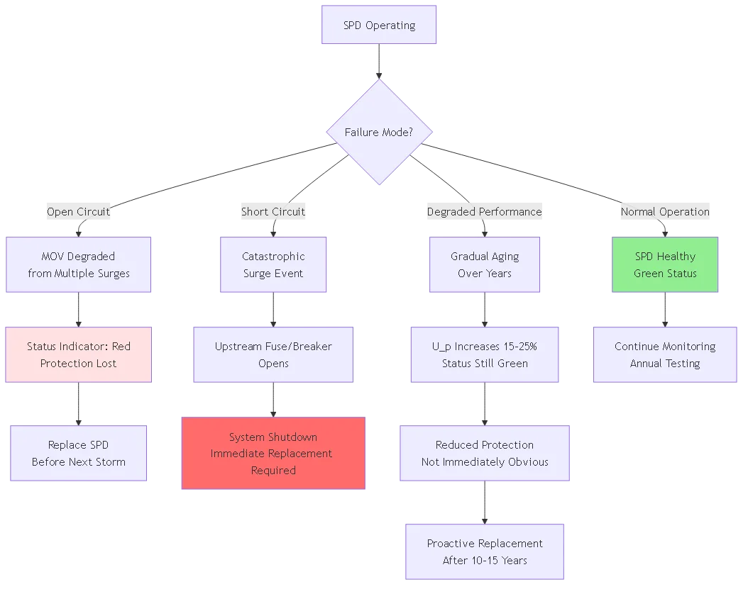
Los dispositivos MOV se degradan gradualmente con cada ciclo de absorción de sobretensiones:
Mecanismo de degradación:
- Cada sobretensión crea microfracturas en la estructura cristalina del varistor
- La tensión de bloqueo aumenta en 1-3% por cada sobretensión de alta energía
- Después de 10-20 sobrecargas importantes, U_p puede superar las especificaciones.
- El aparato se "desgasta" pero no necesariamente falla
Vida útil típica:
- Lugares poco expuestos (llanuras, valles): 20-25 años
- Exposición moderada (estribaciones, suburbios): 15-20 años
- Alta exposición (cumbres, costa): 10-15 años
- Exposición extrema (edificios altos, torres): 5-10 años
Indicadores de sustitución:
- El indicador de estado cambia de verde a rojo/amarillo
- El valor U_p medido supera el valor de la hoja de datos en >15%
- Daños físicos visibles (grietas, decoloración, abombamiento)
- Disparos molestos de los interruptores aguas arriba
La eficacia del SPD disminuye drásticamente con una instalación incorrecta. La longitud total del cable (positivo + negativo + tierra) crea una inductancia parásita que añade tensión al nivel de sujeción:
Fórmula de aumento de tensión por inductancia:
V_inductancia = L × (dI/dt)

Donde:
L = Inductancia del cable (~1µH por metro)
dI/dt = Velocidad de aumento de la corriente (~10kA/µs para rayos)
Ejemplo práctico:
- 0,5 m de cables en total: L = 0,5µH
- V_inductancia = 0,5µH × 10kA/µs = 500 V añadidos
- Sujeción efectiva: 1200V + 500V = 1700V
- 2,0 m de cables en total: L = 2,0µH
- V_inductancia = 2,0µH × 10kA/µs = 2000V añadidos
- Sujeción efectiva: 1200V + 2000V = 3200V (¡daños en el inversor!)
Requisito IEC 61643-11:
- Longitud total máxima del cable: 0,5 m (positivo + negativo + masa combinados)
- Instalación ideal: Cables de <0,3 m en total
- Cada 0,1 m adicional añade ~100 V a la tensión de apriete
Conexión en V (recomendada):
- SPD montado directamente en el punto de unión de la barra colectora
- Cables positivo, negativo y de tierra <0,15m cada uno
- Longitud total del cable: 0,45 m ✅.
- Inductancia parásita mínima
- Tensión de apriete efectiva cercana a la nominal U_pTierra remota (problemática):
- SPD montado en la puerta del armario
- Recorrido del cable de tierra 1-2 m hasta la barra colectora de tierra
- Longitud total del cable: 2-3 m ❌.
- Alta inductancia parásita
- La tensión de bloqueo efectiva puede superar la resistencia del inversor.
⚠️ Error de instalación #1: Montar el SPD en la puerta de la caja con un cable de tierra largo es el error de instalación más común, lo que reduce la eficacia de la protección en 50-70%.

Los inversores monofásicos modernos de 600 V tienen valores de protección de entrada de CC específicos que deben respetar las tensiones de bloqueo de los SPD:
Valores típicos de CC de inversores residenciales:
- Tensión máxima de entrada600 V nominal, 850 V máximo absoluto
- Resistencia a la sobretensión (1 segundo): 1500V típico
- Resistencia a la sobretensión (1 milisegundo): 2000V máximo
- Inmunidad a las sobretensiones6kV según IEEE C62.45 (con SPD adecuado)
Requisitos de coordinación del DOCUP:
SPD U_p (con inductancia) < Inversor 1ms resistir

Ejemplo:
- SPD U_p: 1200V
- Inductancia del cable: +300V (cables de 0,3m)
- Total: 1500V
- Resistencia del inversor: 2000V
- Margen: 500 V
Diseño de sistemas de dos etapas:
Etapa 1: DOCUP a nivel de cadena (tipo 2)
- Ubicación: Caja combinadora en la matriz
- Distancia al inversor: 20-50 m típica
- U_p: 1400V
- I_n: 40kA
- Función: Absorber 80-90% de energía de sobretensión.
Etapa 2: SPD de entrada del inversor (Tipo 3)
- Ubicación: Terminales CC del inversor
- Distancia al inversor: 0 m (montaje directo)
- U_p: 1200V
- I_n: 10kA
- Función: Sujeción final, energía residual 10-20%
Análisis de coordinación:
1. Sobretensión de rayo: 6000V inicial
2. Etapa 1 abrazaderas a: 1400V
3. La impedancia del cable se reduce a: ~1300V en el inversor
4. Etapa 2 más abrazaderas a: 1200V
5. Experiencias del inversor: 1200V máximo
6. Margen de protección: 800V (67% por debajo de soportar)
Coste-beneficio de una etapa frente a dos etapas:
- Una etapa: $150-250 coste total, 85% fiabilidad de protección
- Dos etapas: coste total $300-500, fiabilidad de protección 99%
- Sustitución del inversor: $2000-5000 si falla la protección
- ROI: La protección en dos etapas se amortiza con un solo rayo
Inspección visual (mensual):
- Compruebe el indicador de estado (verde = operativo, rojo/amarillo = sustituir)
- Inspeccionar en busca de daños físicos (grietas, abultamientos, decoloración).
- Compruebe que las conexiones de los cables están bien apretadas (los ciclos térmicos pueden aflojarlas).
- Busque signos de intrusión de agua en el recinto
Pruebas eléctricas (anuales):
1. Prueba de resistencia del aislamiento
- Desconectar el SPD del circuito
- Mida la resistencia a tierra: debe indicar >10MΩ
- Lecturas <1MΩ indican degradación o fallo
2. Prueba de corriente de fuga
- Con el SPD conectado y el sistema a V_oc
- Medir la corriente a través del SPD: debe ser <0,5 mA
- Una fuga mayor indica envejecimiento o sobrecalentamiento
3. Verificación del tiempo de respuesta (equipo especializado)
- Inyectar impulso de prueba de 1kV/µs
- Medir el tiempo de activación del SPD con el osciloscopio
- Verificar t_a <25ns para dispositivos MOV
Criterios de sustitución:
- El indicador de estado muestra el fallo (rojo/amarillo)
- Resistencia del aislamiento <1MΩ
- Leakage current >1 mA
- Daños físicos visibles
- Edad del dispositivo >15 años en lugares de alta exposición
🎯 Consejo profesional: Sustituya los SPD de forma proactiva después de que se produzcan rayos importantes, incluso si el indicador de estado permanece en verde. La degradación interna puede no ser visible inmediatamente, pero reduce la capacidad de protección para futuras descargas.
Problema: La instalación de un SPD U_c de 600 V en sistemas con V_oc >600 V provoca el fallo prematuro del SPD y la pérdida de protección.
Escenarios comunes:
- SPD de 600 V utilizado en la cadena de 17-20 módulos (V_oc = 650-750 V)
- La V_oc en tiempo frío supera los 600 V aunque la V_oc STC sea <600v
- temperature coefficient ignored during designCorrección: Compruebe siempre V_oc a la temperatura más baja prevista (de -10 a -40°C según el clima) y asegúrese de que SPD U_c la supera en 20% como mínimo:
SPD U_c ≥ 1,2 × V_oc(más frío)

Ejemplo:
V_oc @ -10°C = 580V
U_c requerido = 1,2 × 580V = 696V
Seleccione: 1000V U_c SPD (siguiente tamaño estándar) ✅
Problema: La instalación de un SPD con una longitud total de cable superior a 1 m añade una inductancia parásita significativa, lo que reduce la eficacia de sujeción en 50-70%.
Típica mala instalación:
- SPD montado en la puerta del armario
- El cable de tierra atraviesa la caja hasta la barra de puesta a tierra (1,5 m)
- Cables positivo/negativo también prolongados (0,5 m cada uno)
- Total de cables: 2,5 m → ¡añade 2500 V durante sobretensiones rápidas!
Corrección: Monte el SPD en la unión de barras con los tres conductores <0,2 m cada uno: - Utilice el cableado más corto posible - Evite el exceso de cable enrollado (crea inductancia) - Los conductores de los SPD no deben tener curvas cerradas de 90°. - Mida y documente la longitud total del cable <0.5m
Problema: El uso de un único SPD entre positivo y negativo sin conexión a tierra no proporciona protección contra sobretensiones en modo común.
Por qué falla:
- Los rayos inducen tensión en ambos polos simultáneamente
- El SPD diferencial sólo protege contra la diferencia de tensión entre polos
- La sobretensión en modo común (ambos polos suben a la vez) atraviesa sin protección
Corrección: Utilice siempre la configuración SPD de tres hilos:
- Positivo a tierra: un MOV
- Negativo a tierra: un MOV
- Tierra del equipo conectada al electrodo de tierra del edificio
- Protege tanto las sobretensiones en modo común como en modo diferencial.
Problema: Instalación de SPD en armarios calientes sin tener en cuenta el aumento de la tensión de apriete inducido por la temperatura.
Impacto:
- La carcasa NEMA negra alcanza una temperatura interna de 75°C
- La tensión de bloqueo del SPD aumenta 15-20% por el calor
- 1200V nominal U_p se convierte en 1440V real
- Margen de tensión para soportar el inversor reducido peligrosamente
Corrección: Aplique el factor de reducción de temperatura o mejore la gestión térmica:
- Utilice carcasas blancas/grises en lugar de negras (-10 a -15°C)
- Añadir orificios de ventilación en la parte superior/inferior de la caja
- Monte el SPD cerca de la parte superior, donde la temperatura es más alta
- Calcule la U_p reducida y verifique que queda un margen adecuado

Inversión inicial:
- MOV SPD tipo 2 (20kA, 1200V U_p): $150-250
- Mano de obra de instalación (1 hora): $100-150
- Total: $250-400 por instalación
Sistema de dos etapas:
- SPD a nivel de cuerda: $150-250
- Entrada inversor SPD: $100-150
- Mano de obra de instalación (1,5 horas): $150-200
- Total: $400-600 por instalación
Valor de protección:
- Sustitución típica de un inversor de 5 kW: $2.000-3.500
- Pérdida de producción durante la sustitución: $200-400
- Riesgo total: $2.200-3.900 por rayo
Probabilidad de impacto de rayo:
- Lugar de baja exposición: 1 golpe cada 50 años
- Exposición moderada: 1 huelga cada 20 años
- Alta exposición: 1 huelga cada 10 años
Cálculo del ROI (lugar de exposición moderada):
Pérdida esperada sin SPD = $2.500 / 20 años = $125/año
Coste del SPD = $300 instalado
Periodo de amortización = $300 / $125 = 2,4 años ✅

Más de 25 años de vida útil del sistema:
- Con SPD: $300 + $0-500 (posible 1 fallo) = $800
- Sin SPD: 1,25 huelgas × $2.500 = $3.125
- Ahorro neto: $2.325 (290% ROI)
Ingeniería Conclusión: Incluso en zonas de baja exposición, la protección SPD proporciona una rentabilidad de la inversión de 200-500% a lo largo de la vida útil típica de un sistema solar de 25 años.
| Parámetro | Sistema SPD de 600 V | Sistema SPD de 1000 V |
|---|---|---|
| Cadena máxima V_oc | 500 V (12-15 módulos) | 830V (18-22 módulos) |
| U_p típica (sujeción) | 1200-1400V | 2000-2500V |
| Margen de protección del inversor | 300-500V (mejor) | 200-300V (Adecuado) |
| Coste del dispositivo | $150-250 | $200-350 (+30%) |
| MOV Tamaño/Peso | 40-60mm, 200g | 50-80mm, 350g |
| Mejor aplicación | Residencial 3-15kW | Comercial 20-100 kW |
Guía de selección de sistemas:
- Elija un SPD de 600 V: Sistemas residenciales <15kw with 12-15 module strings
- Elija 1000V SPD: Sistemas comerciales >20 kW con 18-22 cadenas de módulos
- Nunca utilice 600 V en sistemas de 1000 V: Fallo inmediato del SPD y pérdida de protección
El valor nominal de 600 V (U_c) representa la tensión continua máxima de funcionamiento que el SPD puede soportar sin degradarse. NO es la tensión del sistema: un SPD de 600 V protege sistemas con V_oc de hasta 500 V aproximadamente para mantener un margen de seguridad de 20%. Para sistemas solares residenciales con 12-15 módulos en serie que producen una tensión de circuito abierto de 420-540V, un SPD de 600V U_c proporciona un margen adecuado. Compruebe siempre que el V_oc de su sistema a la temperatura más fría prevista se mantiene por debajo de 500 V antes de seleccionar un SPD de 600 V.
La tensión de bloqueo (U_p) determina la tensión máxima que atraviesa el inversor durante una sobretensión. Los inversores modernos de 600 V suelen soportar entre 1500 y 2000 V durante breves momentos antes de fallar. Un SPD de 600 V con U_p de 1200 V proporciona un margen de protección de 300-800 V. Las tensiones de apriete más bajas ofrecen mejor protección; por ejemplo, 1100 V U_p frente a 1400 V U_p significa 300 V menos de tensión en los componentes del inversor. Sin embargo, las tensiones de apriete excesivamente bajas requieren materiales de varistor caros, lo que aumenta el coste del SPD entre 2 y 3 veces.
Los SPD de 600 V CC basados en MOV responden en <25 nanoseconds, making them class i devices per iec 61643-11. this near-instantaneous response protects sensitive inverter semiconductors that can fail in 50-100 nanoseconds when exposed to overvoltage. gas discharge tube (gdt) spds respond slower at but offer higher energy capacity. for residential solar applications, mov technology's fast time is more critical than gdt's rating since induced lightning surges rarely exceed 20-40ka.
La vida útil de los SPD varía drásticamente en función de la exposición a los rayos. En los lugares de baja exposición (llanuras, valles), la vida útil es de 20-25 años con una degradación mínima. Los lugares de alta exposición (cimas de montañas, zonas costeras) requieren una sustitución cada 10-15 años, ya que la absorción repetida de sobretensiones degrada el material del varistor. Cada rayo importante (>10kA) aumenta la tensión de apriete en 1-3% por microfractura. Después de 10-20 sobretensiones de alta energía, el SPD se "desgasta" y la U_p supera las especificaciones en 15-20%. La mayoría de los SPD de calidad incluyen indicadores de estado que se vuelven rojos/amarillos cuando es necesario sustituirlos.
Sí, un único SPD de tres hilos (positivo a tierra y negativo a tierra) puede proteger varias cadenas en paralelo conectadas a la misma barra colectora del combinador. El SPD debe tener una capacidad nominal para la corriente máxima combinada de todas las cadenas. Por ejemplo, seis cadenas de 11 A requieren un SPD con I_n ≥ 40 kA (1,5× × 66 A combinados). Sin embargo, el uso de SPD individuales por cadena proporciona un mejor aislamiento de fallos: si una cadena desarrolla un fallo a tierra, sólo se verá afectado el SPD de esa cadena en lugar de perder la protección de todo el conjunto.
La instalación de un SPD infravalorado provoca un fallo inmediato y la pérdida de protección. La sobretensión continua (V_oc superior al valor nominal U_c del SPD) mantiene el MOV en conducción constante, generando calor y degradando rápidamente el material del varistor. En cuestión de días o semanas, el SPD falla en circuito abierto (pérdida de protección) o en cortocircuito (disparo del disyuntor aguas arriba y apagado del sistema). Incluso si el SPD tiene suficiente corriente de choque (I_n), el desajuste de tensión lo hace totalmente inadecuado. Adapte siempre el SPD U_c a la tensión del sistema con un margen mínimo de 20%.
La longitud total del cable del SPD (cable positivo + cable negativo + cable de tierra) debe ser de <0,5 m según IEC 61643-11. Cada metro de cable añade ~1µH de inductancia, lo que contribuye a un aumento de tensión parásita de 1000-2000V durante las sobretensiones de rayos rápidos. Instalación práctica: mida la distancia en línea recta desde la unión de la barra colectora hasta el punto de puesta a tierra, multiplique por 2,5 (factor de encaminamiento del cable) y compruebe que el resultado es <500mm. Si la medición supera los 500 mm, reubique la posición de montaje del SPD más cerca de la barra colectora o utilice un mejor tendido de cables para acortar los cables.
El SPD de 600 V CC es el componente principal de protección contra rayos en 70% de las instalaciones solares residenciales de todo el mundo, por lo que una especificación e instalación adecuadas son fundamentales para la fiabilidad del sistema a largo plazo.
Puntos clave de la ingeniería:
1. Tensión de bloqueo debe permanecer <80% del valor nominal de resistencia de CC del inversor, teniendo en cuenta la reducción de potencia por temperatura y las adiciones de inductancia del cable.
2. Tiempo de respuesta <25 nanoseconds (mov technology) protects sensitive inverter semiconductors that fail in <100 nanoseconds
3. Longitud del cable <0,5 m en total es absolutamente crítico: un exceso de cables puede añadir una tensión parásita de 1000-2000 V, anulando la protección del SPD.
4. Protección en dos etapas ofrecen una fiabilidad de 99% frente a los 85% de una sola etapa, lo que justifica un sobrecoste de 40-60%.
5. Sustitución proactiva después de 10-20 sobretensiones importantes o 15 años en lugares de alta exposición mantiene la fiabilidad de la protección
Comprender la interacción entre la tensión nominal U_c, la tensión de apriete U_p, el tiempo de respuesta y una instalación adecuada garantiza que los sistemas solares residenciales alcancen una vida operativa de más de 25 años con un mínimo de fallos relacionados con los rayos.
Recursos relacionados:
- Diagramas de cableado de instalación de DC SPD para sistemas solares
- Selección de SPD de 1000 V CC para aplicaciones fotovoltaicas comerciales
- Fundamentos de diseño de sistemas de protección contra el rayo solar
¿Está listo para especificar un SPD de 600 V CC para su instalación? Póngase en contacto con el equipo de ingeniería de protección contra rayos de SYNODE para obtener recomendaciones específicas para cada proyecto, incluido el análisis de la tensión de apriete, la optimización de la longitud de los cables y los cálculos de coordinación multietapa para sistemas solares residenciales de 3-20 kW.
Última actualización: Febrero de 2026
Autor: Equipo técnico de SYNODE
Revisado por: Departamento de Ingeniería de Protección contra el Rayo
Palabra clave: 600v cc spd
URL Slug: 600v-dc-spd-voltaje-de-bloqueo-de-ingeniería
Meta Título: Guía técnica del SPD de 600 V CC: Tensión de bloqueo e ingeniería de respuesta
Meta Descripción: Análisis completo de ingeniería de SPD de 600 V CC: cálculos de tensión de bloqueo, especificaciones de tiempo de respuesta, comparación de tecnología MOV frente a GDT y cumplimiento de la norma IEC 61643-11 para sistemas solares residenciales.
Nivel de contenido: Nivel 3 (Contenidos de apoyo)
Embudo de conversión: Parte superior del embudo (concienciación)
Número de palabras objetivo: 2800-4000 palabras
Objetivo Diagramas de sirena: 3
Por favor, configúrelos en los ajustes de Rank Math, luego borre esta casilla antes de publicar.
El valor nominal de 600 V (U_c) representa la tensión continua máxima de funcionamiento que el SPD puede soportar sin degradarse. NO es la tensión del sistema: un SPD de 600 V protege sistemas con V_oc de hasta 500 V aproximadamente para mantener un margen de seguridad de 20%. Para sistemas solares residenciales con 12-15 módulos en serie que producen una tensión de circuito abierto de 420-540V, un SPD de 600V U_c proporciona un margen adecuado. Compruebe siempre que el V_oc de su sistema a la temperatura más fría prevista se mantiene por debajo de 500 V antes de seleccionar un SPD de 600 V.
La tensión de bloqueo (U_p) determina la tensión máxima que atraviesa el inversor durante una sobretensión. Los inversores modernos de 600 V suelen soportar entre 1500 y 2000 V durante breves momentos antes de fallar. Un SPD de 600 V con U_p de 1200 V proporciona un margen de protección de 300-800 V. Las tensiones de apriete más bajas ofrecen mejor protección; por ejemplo, 1100 V U_p frente a 1400 V U_p significa 300 V menos de tensión en los componentes del inversor. Sin embargo, las tensiones de apriete excesivamente bajas requieren materiales de varistor caros, lo que aumenta el coste del SPD entre 2 y 3 veces.
Los SPD de 600 V CC basados en MOV responden en <25 nanosegundos, lo que los convierte en dispositivos de Clase I según la norma IEC 61643-11. Esta respuesta casi instantánea protege a los sensibles semiconductores inversores que pueden fallar en 50-100 nanosegundos cuando se exponen a sobretensiones. Los SPD de tubo de descarga de gas (GDT) responden más lentamente, en 50-100 nanosegundos, pero ofrecen una mayor capacidad energética. Para aplicaciones solares residenciales, el rápido tiempo de respuesta de la tecnología MOV es más crítico que la mayor capacidad energética del GDT, ya que las sobretensiones inducidas por rayos raramente superan los 20-40kA.
La vida útil de los SPD varía drásticamente en función de la exposición a los rayos. En los lugares de baja exposición (llanuras, valles), la vida útil es de 20-25 años con una degradación mínima. Los lugares de alta exposición (cimas de montañas, zonas costeras) requieren una sustitución cada 10-15 años, ya que la absorción repetida de sobretensiones degrada el material del varistor. Cada rayo importante (>10kA) aumenta la tensión de apriete en 1-3% por microfractura. Después de 10-20 sobretensiones de alta energía, el SPD se desgasta y la U_p supera las especificaciones en 15-20%. La mayoría de los SPD de calidad incluyen indicadores de estado que se vuelven rojos/amarillos cuando es necesario sustituirlos.
Sí, un único SPD de tres hilos (positivo a tierra y negativo a tierra) puede proteger varias cadenas en paralelo conectadas a la misma barra colectora del combinador. El SPD debe tener una capacidad nominal para la corriente máxima combinada de todas las cadenas. Por ejemplo, seis cadenas de 11 A requieren un SPD con I_n ≥ 40 kA (1,5× × 66 A combinados). Sin embargo, el uso de SPD individuales por cadena proporciona un mejor aislamiento de fallos: si una cadena desarrolla un fallo a tierra, sólo se verá afectado el SPD de esa cadena en lugar de perder la protección de todo el conjunto.
La instalación de un SPD infravalorado provoca un fallo inmediato y la pérdida de protección. La sobretensión continua (V_oc superior al valor nominal U_c del SPD) mantiene el MOV en conducción constante, generando calor y degradando rápidamente el material del varistor. En cuestión de días o semanas, el SPD falla en circuito abierto (pérdida de protección) o en cortocircuito (disparo del disyuntor aguas arriba y apagado del sistema). Incluso si el SPD tiene suficiente corriente de choque (I_n), el desajuste de tensión lo hace totalmente inadecuado. Adapte siempre el SPD U_c a la tensión del sistema con un margen mínimo de 20%.
La longitud total del cable del SPD (cable positivo + cable negativo + cable de tierra) debe ser de <0,5 m según IEC 61643-11. Cada metro de cable añade ~1µH de inductancia, lo que contribuye a un aumento de tensión parásita de 1000-2000V durante las sobretensiones de rayos rápidos. Instalación práctica: mida la distancia en línea recta desde la unión de la barra colectora hasta el punto de puesta a tierra, multiplique por 2,5 (factor de encaminamiento del cable) y compruebe que el resultado es <500mm. Si la medición supera los 500 mm, reubique la posición de montaje del SPD más cerca de la barra colectora o utilice un mejor tendido de cables para acortar los cables.