Address
304 North Cardinal
St. Dorchester Center, MA 02124
Work Hours
Monday to Friday: 7AM - 7PM
Weekend: 10AM - 5PM
Address
304 North Cardinal
St. Dorchester Center, MA 02124
Work Hours
Monday to Friday: 7AM - 7PM
Weekend: 10AM - 5PM

Understanding surge protection DC installation requirements ensures code-compliant photovoltaic system protection meeting NEC 690.35 standards. This comprehensive installation guide examines proper SPD placement techniques, grounding electrode installation methods, conductor termination procedures, and inspection protocols. Electrical contractors and installers will find detailed compliance checklists, installation best practices, and authority having jurisdiction (AHJ) acceptance strategies for professional-grade surge protection installations.
Installing surge protection DC devices requires more than mounting components in enclosures. NEC 690.35 establishes mandatory requirements for SPD installation location, connection methods, disconnecting means, and ground fault protection integration. Compliant installations protect against surge damage while satisfying electrical inspection requirements preventing project delays and costly reinstallation work. Proper installation techniques also ensure protection system performance matches design specifications throughout 25-year system operational lifetime.
NEC 690.35 (2023 edition) mandates surge protective devices on all DC photovoltaic source circuits and output circuits unless system meets specific exemption criteria. This represents significant change from previous editions where surge protection was recommended but not universally required. The mandatory requirement recognizes lightning-induced surge damage as leading cause of PV system failures and establishes minimum protection baseline for all installations.
The specific NEC 690.35 language states: “Surge-protective devices shall be installed on DC PV source circuits and PV output circuits unless the PV system meets all of the following conditions…” followed by exemption criteria. Most practical installations cannot meet all exemption requirements making SPD installation mandatory for essentially all residential, commercial, and utility-scale projects.
Exemption criteria (all must be met simultaneously):
– PV system located in area with ground flash density less than 0.25 flashes/km²/year (extremely rare in populated areas)
– System uses metal raceway enclosing all PV source and output circuit conductors
– System includes properly bonded metallic cable tray for all conductors
– All equipment includes manufacturer-integrated surge protection exceeding minimum standards
Since most installations use exposed rooftop conductors and operate in moderate-to-high lightning exposure areas, exemption rarely applies. Plan for mandatory SPD installation during project design phase avoiding last-minute compliance scrambles during final inspection.
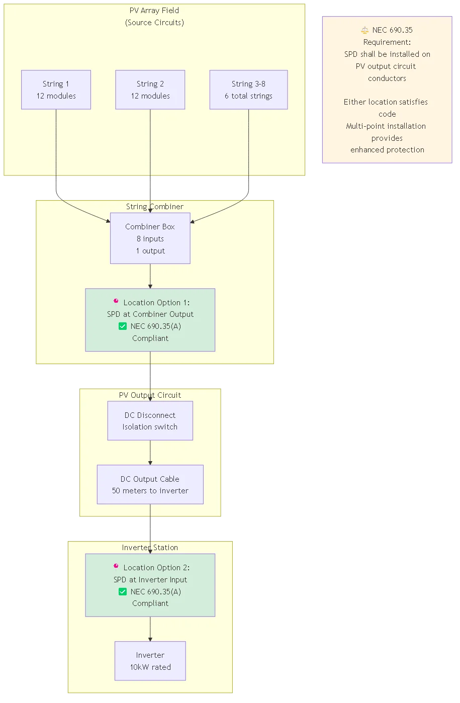
NEC 690.35(A) specifies acceptable SPD installation locations ensuring protection at appropriate system points. Surge protective devices must install “on the photovoltaic output circuit conductors” which permits multiple interpretation options. Common compliant installation locations include:
At DC combiner or recombiner outputs: Installing SPD at main DC combiner provides centralized protection where all array strings consolidate before routing to inverter station. This location suits large installations with multiple string combiners feeding central collection point. Single SPD installation protects all downstream equipment including DC disconnects, monitoring equipment, and inverter DC inputs.
At inverter DC input terminals: Installing SPD immediately before inverter DC terminals provides final equipment-level protection. This location makes sense for smaller installations with few strings running directly to inverter without intermediate combiners. Close proximity to protected equipment minimizes unprotected conductor length reducing induced surge coupling between SPD and sensitive inverter electronics.
Multi-point installation: Larger installations may install SPDs at multiple locations creating defense-in-depth protection. Typical configuration uses SPDs at string combiner outputs plus additional SPD at central recombiner or inverter input. This coordinated approach distributes surge energy across multiple devices while providing backup protection if individual SPD fails.
| Installation Location | NEC Compliance Status | Protection Effectiveness | Typical Application |
|---|---|---|---|
| Main DC Combiner Output | ✅ Compliant per 690.35(A) | Good – Central protection point | Commercial 50-500kW systems |
| Inverter DC Input | ✅ Compliant per 690.35(A) | Excellent – Equipment-level | Residential 3-10kW systems |
| Array Junction Box | ✅ Compliant if on output circuit | Moderate – Array-level | Ground-mount utility-scale |
| Individual String Combiners | ✅ Compliant if output circuit | Very Good – Distributed | Large commercial 500kW+ |
💡 Key Insight: NEC 690.35 permits SPD installation at various locations along PV output circuit. Choose location balancing code compliance, protection effectiveness, installation practicality, and cost optimization. Document installation location on electrical drawings and as-built documentation ensuring inspector can verify compliance during final review.
Most modern DC surge protective devices mount on standard 35mm DIN rail per IEC 60715 specifications simplifying installation and allowing easy replacement. DIN rail mounting provides vibration resistance, proper thermal management, and organized enclosure layout facilitating inspection and maintenance. Proper DIN rail installation requires attention to mounting clip engagement, rail loading capacity, and adequate spacing between adjacent devices.
Step-by-step DIN rail mounting procedure:
1. Verify rail installation: Ensure DIN rail firmly mounts to back panel using appropriate fasteners (M4 or M5 screws typical) at maximum 250mm spacing preventing rail deflection under device load. Level rail horizontally using bubble level—sloped rails cause devices to slide creating poor connections.
2. Prepare SPD mounting: Lift rear mounting clip on SPD to open position allowing device to slide onto rail. Inspect clip for damage or deformation potentially preventing secure attachment. Some devices include removable mounting clips—verify clip properly installs before attempting rail mounting.
3. Engage top rail edge: Hook top portion of SPD mounting clip over front edge of DIN rail ensuring full engagement across device width. Partially engaged devices may appear mounted but lack mechanical security causing installation failures.
4. Snap bottom clip: Press firmly on SPD housing near bottom mounting area until distinct “click” indicates mounting clip has engaged rear DIN rail edge. Verify secure mounting by attempting to lift device off rail—properly mounted SPDs resist removal without actuating release mechanism.
5. Verify spacing: Maintain minimum spacing between adjacent SPDs per manufacturer specifications (typically 10-20mm) ensuring adequate ventilation and preventing thermal coupling. Overheated SPDs exhibit reduced surge capacity and shortened service life.
6. Test mechanical security: After mounting all devices, perform pull test attempting to remove each SPD by pulling forward (without actuating release). Properly mounted devices require deliberate release mechanism operation for removal preventing accidental dislodging during subsequent installation work.
Professional installations integrate SPDs with combiner or inverter busbars using properly sized terminal blocks or direct busbar connections. Terminal block integration provides organized conductor management, simplified troubleshooting, and clean enclosure appearance meeting professional quality standards. Busbar connections offer lowest contact resistance and highest current capacity but require precision drilling and custom fabrication.
Terminal block integration best practices:
– Select terminal blocks rated for system DC voltage (600V, 1000V, or 1500V) plus adequate derating margin
– Verify terminal current rating exceeds maximum DC current by 125% per NEC 690.8(B)(1)
– Use compression terminals on conductor ends ensuring gas-tight connections preventing oxidation
– Arrange terminals in logical order (positive conductor, SPD input, SPD output, negative conductor) simplifying circuit tracing
– Label terminal blocks using permanent marker or labeling machine identifying circuit function
Direct busbar connection procedure:
Installing SPDs directly on combiner or inverter main busbars requires careful measurement, drilling, and hardware selection. Busbar connections provide lowest impedance path optimizing SPD response time and clamping effectiveness. However, this installation method demands precision fabrication and appropriate mechanical/electrical clearances.
Measure distance between SPD terminal centers (typical spacing 28-38mm for two-pole devices). Transfer measurements to busbar using spring-loaded center punch marking drill locations. Drill appropriate diameter holes (typically 6-8mm) using sharp drill bit and cutting fluid preventing burrs and maintaining busbar integrity. Deburr holes using countersink or deburring tool creating smooth edges preventing insulation damage on mounting hardware.
Mount SPD using stainless steel machine screws, split lock washers, and flat washers creating secure mechanical and electrical connection. Torque fasteners to manufacturer specifications (typically 4-6 N⋅m for M6 hardware, 8-12 N⋅m for M8) using calibrated torque wrench. Under-torqued connections create high contact resistance causing heating and eventual failure. Over-torqued connections damage SPD terminals or crush internal protection elements.
Surge protective device grounding connections must terminate at system grounding electrode per NEC Article 250 requirements establishing common reference point for all protective devices. Grounding electrode system quality directly affects SPD effectiveness—high ground impedance creates additional voltage drop during surge diversion potentially allowing protected equipment to see voltages exceeding insulation ratings despite properly rated SPDs.
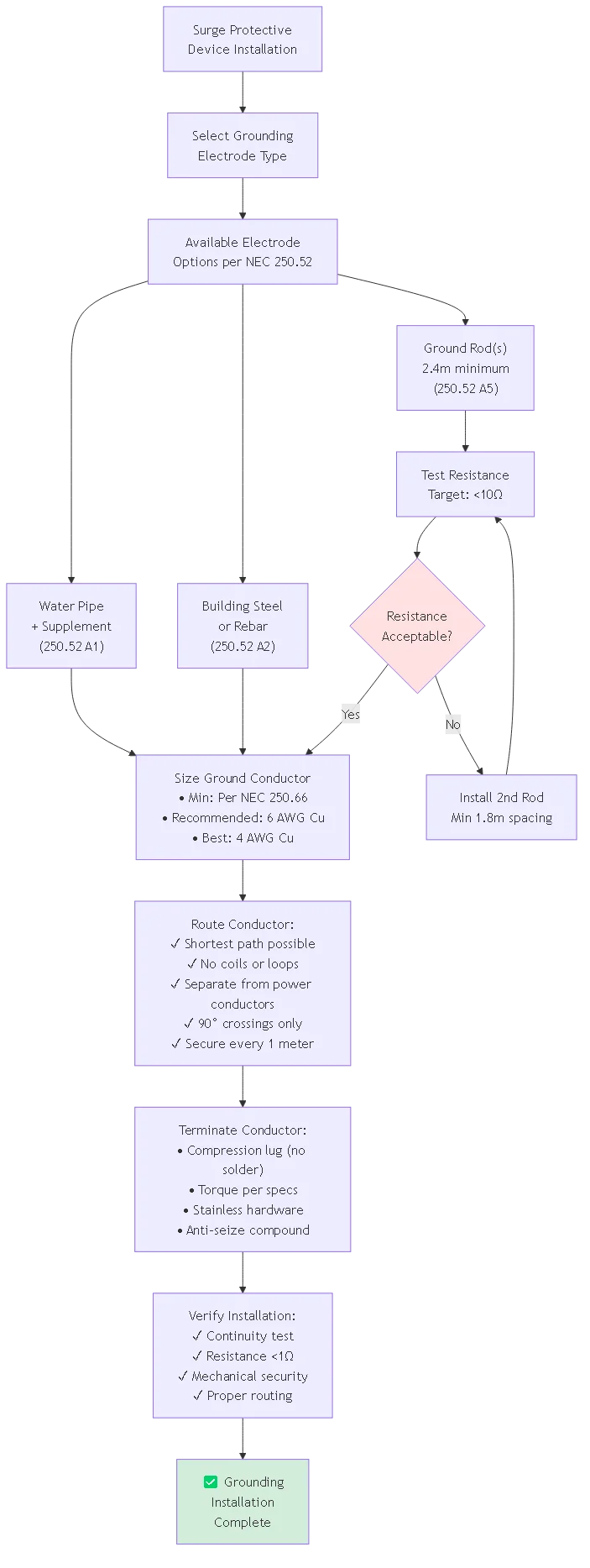
NEC 250.52 recognizes several electrode types suitable for SPD grounding:
Metal underground water pipe (250.52(A)(1)): Where available, connection to metal water service pipe provides low-impedance ground reference. However, water pipe alone does not satisfy code—supplemental electrode required per 250.53(D)(2). Connect within 1.5 meters of water pipe entry to building using ground clamp listed for direct burial application.
Building steel structure (250.52(A)(2)): Concrete-encased foundation rebar or structural steel effectively grounded by earth contact provides excellent electrode. This electrode type suits new construction where foundation access exists during installation. Verify minimum 6 meters of rebar or structural steel maintains earth contact meeting code requirements.
Ground rod or pipe (250.52(A)(5)): Copper-clad steel or stainless steel ground rods minimum 2.4 meters length driven to required depth provide reliable electrode when other types unavailable. Single rod rarely achieves <25Ω resistance required by 250.53(A)(2) necessitating installation of second rod spaced minimum 1.8 meters from first rod. Test resistance using fall-of-potential method verifying compliance. Ground ring (250.52(A)(4)): Bare copper conductor minimum 6 AWG encircling building buried minimum 750mm below grade contacting earth minimum 6 meters provides effective electrode for larger installations. Ground ring installation suits utility-scale projects where single-point grounding proves impractical.
NEC 690.35(D) requires SPD ground conductor to be “as short and straight as practicable” minimizing conductor inductance affecting high-frequency surge diversion. Conductor inductance creates voltage drop proportional to current rate of change potentially allowing thousands of volts to appear across even short ground leads during fast-rising surge events.
Ground conductor sizing requirements:
NEC Table 250.66 establishes minimum ground conductor size based on largest conductor supplying equipment. For PV systems, this references DC output circuit conductor size. However, surge protection applications often justify oversized ground conductors beyond minimum code requirements reducing inductance and resistance improving SPD performance.
– Minimum per NEC: 8 AWG copper for systems with output conductors ≤2 AWG
– Minimum per NEC: 6 AWG copper for systems with output conductors 1/0-3/0 AWG
– Recommended practice: 6 AWG copper minimum regardless of system size
– Best practice: 4 AWG copper for critical installations prioritizing protection over cost
Ground conductor routing technique:
Install ground conductor using shortest possible path from SPD ground terminal to grounding electrode connection point. Avoid coiling excess conductor length—coiled conductors exhibit dramatically increased inductance compared to straight runs. For every meter of conductor length, typical inductance adds 1.5μH creating proportional voltage drop during surge events.
Route ground conductor separately from power conductors preventing electromagnetic coupling. When ground conductor must cross power conductors, maintain 90-degree crossing angle minimizing parallel run length. Secure ground conductor every 1 meter using appropriate cable supports preventing conductor movement and maintaining intended routing.
Ground conductor terminations require particular attention ensuring low-resistance, corrosion-resistant connections. Use compression lugs crimped with appropriate hex die for conductor size—never use solder for ground terminations since solder can melt during high-current surge events. Connect lug to SPD ground terminal using stainless steel hardware torqued to manufacturer specifications.
| Ground Conductor Length | Typical Inductance | Voltage Drop @ 10kA/μs | Impact Assessment |
|---|---|---|---|
| 150mm (6 inches) | ~225nH | ~2,250V | ✅ Good – Minimal impact |
| 300mm (12 inches) | ~450nH | ~4,500V | ⚠️ Acceptable – Moderate impact |
| 600mm (24 inches) | ~900nH | ~9,000V | ❌ Poor – Significant impact |
| 1000mm (40 inches) | ~1,500nH | ~15,000V | ❌ Unacceptable – Major degradation |
⚠️ Important: Excessive ground conductor length severely degrades SPD protection effectiveness regardless of device quality. A premium 3000V VPL SPD with 1-meter ground lead may allow 18,000V total voltage (3000V SPD clamping + 15,000V ground lead drop) at protected equipment—worse than unprotected installation! Always minimize ground conductor length treating it as critical protection parameter equivalent to SPD rating selection.
Proper connection sequence for two-pole DC SPDs ensures safe installation preventing accidental short circuits or equipment damage. DC photovoltaic systems maintain substantial voltage even during installation—modules generate voltage whenever exposed to light regardless of system state. Following correct connection sequence and verifying polarity before energizing prevents costly installation errors.
Recommended connection sequence (assuming de-energized or covered modules):
1. Verify zero voltage: Use multimeter rated for DC voltage range measuring voltage between positive and negative conductors. Confirm reading shows zero or near-zero voltage (< 5V residual from module capacitance). If voltage present, troubleshoot to identify source before proceeding.
2. Connect SPD ground first: Always establish ground connection before connecting power conductors. This ensures any fault during subsequent connections will have established ground path preventing equipment damage or personnel shock hazard.
3. Connect negative (−) conductor: Install negative DC conductor to SPD negative terminal. Negative conductor typically connects to grounded conductor in many PV system configurations making it safer to connect first reducing shock hazard potential.
4. Connect positive (+) conductor: After negative conductor securely terminates, install positive DC conductor to SPD positive terminal. Double-check polarity marking on SPD housing ensuring positive circuit conductor connects to terminal marked “+” or “L+”.
5. Verify connections: Inspect all terminations confirming proper torque, conductor insertion depth, and absence of stray strands. Use insulated mirror or phone camera to inspect rear of terminal blocks verifying conductors fully seat in terminal mechanism.
6. Document installation: Take photographs showing completed installation including SPD location, conductor routing, polarity markings, and ground connection. Documentation proves proper installation during inspection and provides reference for future maintenance.
Proper terminal torque represents critical installation parameter directly affecting connection reliability and SPD performance. Under-torqued terminals create high-resistance connections causing heating, voltage drop, and eventual failure. Over-torqued terminals damage conductor strands, crack terminal blocks, or crush internal SPD components.
NEC 110.14(D) requires tightening of terminals “in accordance with manufacturer’s instructions” making published torque specifications mandatory rather than optional guidance. Use calibrated torque screwdriver or torque wrench appropriate for specified torque range—do not estimate torque by “feel” as even experienced electricians cannot consistently achieve proper torque without tools.
Typical SPD terminal torque specifications:
– M3 terminal screws: 0.5-0.6 N⋅m (4.4-5.3 lb⋅in)
– M3.5 terminal screws: 0.8-1.0 N⋅m (7.1-8.8 lb⋅in)
– M4 terminal screws: 1.2-1.5 N⋅m (10.6-13.3 lb⋅in)
– M5 terminal screws: 2.5-3.0 N⋅m (22.1-26.5 lb⋅in)
– M6 terminal screws: 4.0-6.0 N⋅m (35.4-53.1 lb⋅in)
After initial tightening, verify torque by attempting to turn fastener additional 1/8 turn. Properly torqued connections resist further rotation without significant force. Mark torqued connections using paint marker or torque stripe allowing visual verification during inspection that fastener hasn’t loosened during vibration or thermal cycling.
Some manufacturers specify two-stage torque procedure: initial tightening to 50% of specified torque, verify conductor seating, then final tightening to 100% specification. This procedure ensures uniform pressure distribution across terminal contact area improving connection reliability especially for fine-strand flexible conductors that compress under pressure.
Proper conductor preparation prevents connection problems including strand protrusion, insulation damage, and inadequate contact area. Conductors connecting to SPD terminals require precise stripping length, clean cut ends, and appropriate termination hardware matching terminal design.
Conductor stripping procedure:
Measure required strip length from terminal block specifications (typically 8-12mm for screw terminals, 10-14mm for spring-cage terminals). Mark conductor insulation at appropriate distance using marker or thumbnail impression. Strip insulation using automatic wire stripper adjusted for conductor size—avoid manual knife stripping which damages conductor strands and creates inconsistent strip length.
Inspect stripped conductor for damage including nicked strands, incomplete insulation removal, or excessive strip length. Damaged conductors require re-stripping at different location obtaining clean conductor end. Twist stranded conductor ends clockwise (viewed from conductor end) consolidating strands and preventing strand separation during insertion.
For screw terminal connections, bend stripped conductor end into “shepherd’s crook” matching terminal screw direction ensuring clockwise screw rotation pulls conductor into terminal rather than pushing out. The hook should wrap 2/3 to 3/4 around screw shaft—incomplete wrapping creates inadequate contact area while excessive wrapping causes conductor overlap preventing proper seating.
Spring-cage terminals eliminate termination hardware simplifying installation. Insert stripped conductor into terminal opening until it stops against internal backstop. Verify minimum insertion depth (typically 10mm) exposing no bare conductor outside terminal housing. Attempt to withdraw conductor with moderate force—properly inserted conductors resist removal without actuating release mechanism.
NEC 690.35(E) mandates specific labeling for surge protective device installations providing clear identification and installation information. Required labels must use permanent marking methods resisting fading, weathering, and cleaning solvents throughout system service life. Pre-printed labels from SPD manufacturer typically satisfy requirements but verify content includes all mandatory elements.
Required label information per NEC 690.35(E):
– “Surge Protective Device” or “SPD”: Clear identification as surge protection equipment
– SPD type classification: “Type 1” or “Type 2” matching IEC 61643-31 classification
– Nominal discharge current rating: “In = 20kA” or equivalent specification
– Voltage rating: Maximum continuous operating voltage (MCOV) or rated voltage
– Short-circuit current rating (if applicable): “SCCR = 10kA” for UL-listed devices
– “Service” or “Line” side indication showing where connection terminals face system source
Additional recommended labeling includes:
– Installation date allowing age-based replacement scheduling
– Installer identification for warranty and follow-up questions
– Inspection date and inspector signature documenting code compliance verification
– As-built drawing reference showing SPD location on electrical single-line diagram
Professional installations create comprehensive documentation package proving NEC compliance and providing reference for future maintenance. Documentation becomes especially valuable during warranty claims, insurance investigations after surge damage, or system ownership transfers where new owner requires complete as-built information.
Essential documentation elements:
Installation photographs: Capture overall enclosure view showing SPD location, close-up images of terminations showing conductor preparation and torque markings, ground connection details, and label application. Minimum 4-6 photographs per installation location documenting installation quality and code compliance.
Test reports: Document pre-installation resistance testing of grounding electrode system, continuity testing of ground conductor path, and insulation resistance testing of DC circuits before SPD installation. Record measured values with date, time, tester identification, and test equipment serial numbers.
Manufacturer documentation: Retain SPD product specification sheets, installation instructions, test reports, and certificates of conformity. These documents prove device ratings claimed on permit application and provide specifications needed for future replacement part procurement.
As-built electrical drawings: Update single-line diagrams showing actual SPD installation locations, conductor routing, and ground connection points. As-built drawings reflect field changes from original design ensuring accuracy for troubleshooting and future modifications.
Create documentation package as PDF file stored on project management system with backup copies provided to system owner. Include documentation package with project close-out submittals satisfying owner requirements and electrical inspection final approval process.
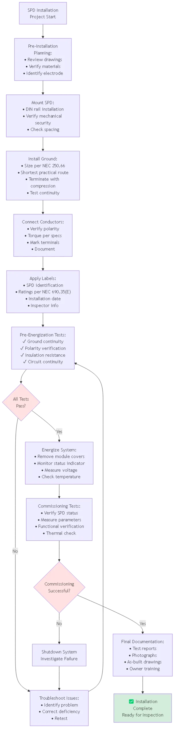
Complete comprehensive inspection before energizing surge protection installation preventing equipment damage and identifying installation errors correctable before powering system. Pre-energization verification takes 15-30 minutes per installation location but eliminates costly troubleshooting and repair work resulting from uncaught installation mistakes.
Visual inspection checklist:
✓ SPD mounting security: Verify device firmly attaches to DIN rail or mounting surface without movement when force applied
✓ Terminal connections: Confirm all conductors properly terminate with correct polarity and adequate torque
✓ Conductor routing: Check conductors follow neat paths without sharp bends, excessive length, or contact with sharp edges
✓ Ground conductor: Verify shortest practical route from SPD to grounding electrode without coils or loops
✓ Clearances: Measure minimum clearance from SPD energized parts to grounded enclosure meets NEC and manufacturer requirements
✓ Labeling: Confirm required labels applied and information complete per NEC 690.35(E)
✓ Status indicator: Note SPD indicator status before energization establishing baseline for comparison
Electrical testing procedure:
Use digital multimeter rated for DC voltage and resistance measurements verifying installation integrity before energizing SPD.
1. Ground continuity test: Measure resistance between SPD ground terminal and main grounding electrode. Target reading <1Ω confirms adequate ground path. Resistance >2Ω indicates high-resistance connection requiring investigation and correction.
2. Polarity verification: With modules covered or system de-energized, use ohmmeter measuring resistance between SPD positive terminal and known system positive conductor. Very low resistance (< 1Ω) confirms correct polarity. High resistance (> 1MΩ) indicates reverse polarity requiring correction before energizing.
3. Insulation resistance: Measure insulation resistance between positive conductor and ground, then negative conductor and ground. Target reading >1MΩ confirms adequate insulation integrity. Lower readings suggest insulation damage, moisture ingress, or incorrect wiring requiring correction.
4. Circuit continuity: Verify electrical continuity through complete DC circuit from modules through SPD to inverter. This test confirms all connections properly made and no open circuits exist preventing system operation.
After successful pre-energization testing, carefully energize system while monitoring for proper operation and absence of fault conditions. Commissioning represents critical installation phase where design, installation quality, and component performance prove out under actual operating conditions.
Commissioning procedure:
1. Remove module covers: If modules were covered during installation, carefully remove covering materials allowing modules to generate voltage. Monitor voltage rise using multimeter confirming proper polarity and expected voltage level.
2. Verify SPD status: Observe SPD status indicator confirming “healthy” or “normal” indication (typically green LED or mechanical flag). Immediate fault indication suggests installation error requiring shutdown and investigation.
3. Measure operating voltage: Record DC system voltage at SPD location comparing to design calculations. Voltage should match expected open-circuit voltage based on module count, solar irradiance, and temperature. Significant deviation indicates potential wiring error or module problem.
4. Monitor SPD temperature: After 15-30 minutes operation under full sun conditions, use infrared thermometer measuring SPD enclosure temperature. Device temperature should remain within 10°C of ambient temperature. Excessive heating indicates incorrect MCOV rating, poor terminal connections, or defective SPD requiring immediate investigation.
5. System functional test: Verify inverter operates normally producing expected power output based on solar conditions. Proper inverter operation confirms SPD installation hasn’t introduced circuit problems affecting system performance.
6. Document commissioning: Record all measured parameters, observations, and photograph final installation. Obtain electrical inspector approval if required by jurisdiction. Provide commissioning report to system owner including all test data and operational recommendations.
| Test Parameter | Target Value | Acceptable Range | Action if Outside Range |
|---|---|---|---|
| Ground Resistance | <1Ω | 0.1-2Ω | Investigate connections if >2Ω |
| Insulation Resistance | >1MΩ | 1-100MΩ+ | Troubleshoot if <500kΩ |
| Operating Voltage | Per design calc | ±5% of design | Verify circuit if outside ±10% |
| SPD Temperature | Ambient +5°C | Ambient to +15°C | Shutdown if >ambient +20°C |
🎯 Pro Tip: Create standardized commissioning checklist specific to your installation practices and local code requirements. Laminated checklist used during every installation ensures consistent quality and prevents skipped steps. Digital checklist using tablet or smartphone allows photo documentation attached directly to each verification item creating complete commissioning record proving quality workmanship.
NEC 690.35(A) requires surge protective devices “on the photovoltaic output circuit conductors” which permits several compliant installation locations. Acceptable locations include DC combiner box outputs, DC disconnect outputs, or inverter DC input terminals—any location along PV output circuit satisfies code. Choose location balancing protection effectiveness, accessibility for maintenance, and installation practicality.
Single-point installation at inverter DC input provides simplest code-compliant option for residential systems. Commercial installations often install SPDs at main DC combiner protecting all downstream equipment with single device. Utility-scale projects may use multi-point installation combining protection at array field combiners plus inverter inputs creating defense-in-depth. Document selected installation location on electrical drawings ensuring inspector can verify compliance during review.
Authority having jurisdiction may interpret NEC 690.35 requiring specific installation location based on local amendments or standard practice. Consult AHJ before finalizing installation location avoiding rejection during final inspection and costly reinstallation work.
NEC 690.35(D) requires ground conductor to be “as short and straight as practicable” without specifying exact maximum length. Industry best practice recommends maximum 300mm (12 inches) total length from SPD ground terminal to grounding electrode connection. Shorter lengths provide better protection—150mm (6 inches) represents excellent target for installations where enclosure layout permits.
Ground conductor length affects SPD performance through inductance. Each meter of conductor adds approximately 1.5μH inductance creating voltage drop during fast-rising surge currents. For 10kA surge with 1μs rise time (di/dt = 10kA/μs), 300mm conductor (450nH) creates V = L × di/dt = 450nH × 10kA/μs = 4500V additional voltage drop. This 4500V adds to SPD clamping voltage potentially exceeding protected equipment insulation rating.
When enclosure layout prevents achieving short ground conductor, consider alternative mounting locations bringing SPD closer to grounding point. In extreme cases, specify SPD with integrated ground stud allowing direct connection to enclosure back panel eliminating separate ground conductor. This direct-mount approach minimizes inductance optimizing protection effectiveness.
Electrical code requirements for who may install surge protection vary by jurisdiction. Most US states require licensed electrician for any work on electrical systems operating above 50V including photovoltaic DC circuits. Some jurisdictions permit homeowner to perform work on own property but still require electrical permit and inspection. Commercial installations universally require licensed electrician and documented training on PV systems.
Even where code permits homeowner installation, professional installation provides significant advantages. Licensed electricians understand code requirements, proper installation techniques, and testing procedures ensuring compliant installation passing inspection first attempt. Professional installation also satisfies equipment warranty requirements—many SPD manufacturers void warranty if device installed by unlicensed personnel.
DIY installation creates liability concerns if subsequent surge damage occurs. Insurance companies may deny claims arguing improper installation contributed to damage. Professional installation provides documentation trail proving code-compliant work protecting homeowner from liability questions. The modest cost difference between DIY and professional installation ($200-500 for most residential systems) represents worthwhile investment for peace of mind.
Installing two-pole DC SPD with reversed polarity (positive conductor to negative terminal, negative to positive terminal) typically does not create immediate safety hazard but may affect protection performance. Most modern DC SPDs use metal oxide varistors exhibiting bidirectional voltage clamping—device functions regardless of polarity orientation providing some protection even when connected backward.
However, reversed polarity prevents proper coordination with ground fault protection devices and arc fault circuit interrupters that monitor current balance between positive and negative conductors. Reversed SPD connections alter normal current flow patterns potentially causing nuisance trips of protective devices. Some advanced SPDs include status monitoring circuits detecting polarity-dependent system voltages—reversed connections prevent these monitoring features from operating correctly.
Correct installation errors immediately upon discovery. De-energize system (or cover modules), verify zero voltage, swap SPD conductor connections to correct terminals matching polarity markings. Document correction with photographs and note in project records. Inform electrical inspector of correction ensuring proper documentation in approved plans.
NEC 690.35(F) requires “readily accessible” SPD installation permitting inspection without dismounting equipment or using ladders/lifts. Establish regular inspection schedule checking SPD status indicators and physical condition. Quarterly visual inspection (every 3 months) represents best practice for critical installations. Annual inspection satisfies minimum acceptable frequency for most applications.
Quarterly inspection procedure takes 5-10 minutes checking status indicator shows “healthy” condition, verifying enclosure integrity without damage or signs of overheating, looking for loose conductor connections, and documenting inspection date. Some SPDs include trip counter or electronic log recording surge event frequency—review logged data identifying installations experiencing frequent surge activity requiring enhanced protection or electrical system investigation.
Annual comprehensive inspection supplements quarterly visual checks with electrical testing. Measure ground resistance verifying value remains below 2Ω. Use infrared camera scanning for hot spots indicating poor connections or degraded components. Document inspection findings with photographs comparing to previous inspection images identifying degradation trends. Replace SPDs showing significant degradation before complete failure eliminates protection.
Long ground conductor runs represent most common installation error dramatically degrading protection effectiveness. Electricians accustomed to power circuit installation may not recognize ground conductor length critically affects high-frequency surge performance. Install SPD as close as possible to grounding electrode or main grounding busbar achieving shortest practical ground path—never prioritize convenient SPD location over minimizing ground conductor length.
Inadequate terminal torque causes high-resistance connections creating heating and eventual failure. Use calibrated torque tools appropriate for specified torque range—do not estimate torque by feel. Under-torqued connections account for estimated 30% of SPD field failures based on manufacturer warranty analysis.
Incorrect MCOV selection from failing to account for temperature-compensated voltage extremes causes premature SPD failure. Module open-circuit voltage increases significantly at low temperatures potentially exceeding SPD MCOV rating if inadequate margin provided. Always calculate required MCOV from worst-case cold temperature Voc plus minimum 25% margin.
Missing or incomplete labels prevent inspector approval and create confusion during future maintenance. Apply all required labels per NEC 690.35(E) before requesting inspection avoiding rejection and re-inspection fees. Use permanent label maker or durable pre-printed labels—handwritten labels often fade making information unreadable within 1-2 years.
Utility-scale surge protection installations follow identical fundamental principles but scale implementation to match larger system size and higher equipment values. Multi-megawatt installations typically specify multi-point SPD placement creating defense-in-depth with protection at array field combiners, central recombiners, and individual inverter DC inputs. This distributed protection requires careful coordination analysis ensuring proper energy distribution between protection stages.
Utility-scale projects demand comprehensive documentation exceeding residential requirements. Commissioning documentation includes full surge testing reports measuring actual protection levels, thermal imaging surveys of all terminations, ground resistance testing at each protection location, and witnessed testing by owner’s representative or third-party commissioning agent. Documentation package becomes permanent facility record supporting ongoing maintenance and warranty claims.
Safety requirements escalate for utility-scale installations. Arc flash hazard assessment mandatory per NFPA 70E calculating incident energy at SPD locations and specifying personal protective equipment requirements. Installations often specify remote rack-out systems allowing SPD replacement without personnel exposure to energized parts. Safety procedures development and worker training become essential project elements beyond equipment installation.
Professional surge protection DC installation requires comprehensive understanding of NEC 690.35 requirements, proper mounting techniques, grounding system installation, and commissioning procedures. Code-compliant installations protect photovoltaic systems against lightning-induced surge damage while satisfying electrical inspection requirements and ensuring protection system performance throughout 25-year operational lifetime.
Key Takeaways:
1. NEC 690.35 mandates SPD installation on PV output circuits with specific location, connection, and labeling requirements
2. Minimize ground conductor length to maximum 300mm treating it as critical performance parameter affecting protection effectiveness
3. Use calibrated torque tools achieving manufacturer-specified terminal torque preventing high-resistance connections causing premature failure
4. Complete pre-energization testing verifying ground continuity, polarity, insulation resistance, and circuit integrity before powering system
5. Create comprehensive documentation with photographs, test reports, and as-built drawings proving code compliance and supporting future maintenance
Proper installation techniques directly determine whether surge protection system performs as designed or fails during first major surge event leaving expensive equipment unprotected. Investment in quality installation practices—using proper tools, following systematic procedures, and thorough testing—pays dividends through reliable protection system operation and electrical inspection approval without costly correction work.
Related Resources:
– DC SPD Wiring Diagram: Step-by-Step Installation
– DC Surge Protection System Design: Multi-Stage Coordination
– 1000V DC SPD Selection: Utility-Scale Requirements
Ready to install code-compliant surge protection for your photovoltaic projects? Contact our technical support team for installation assistance, pre-inspection review, and commissioning guidance ensuring first-time electrical inspection approval and reliable surge protection system performance.
Last Updated: November 2025
Author: SYNODE Technical Team
Reviewed by: Field Installation Services Department