Address
304 North Cardinal
St. Dorchester Center, MA 02124
Work Hours
Monday to Friday: 7AM - 7PM
Weekend: 10AM - 5PM
Address
304 North Cardinal
St. Dorchester Center, MA 02124
Work Hours
Monday to Friday: 7AM - 7PM
Weekend: 10AM - 5PM


Dc spd meaning:DC SPD—Surge Protection Device for direct current systems—represents critical safety equipment protecting solar photovoltaic installations from destructive voltage transients. Understanding what SPDs are, how they work, and the key technologies inside them helps system designers and installers select appropriate protection for reliable solar operations. This comprehensive guide explains DC SPD fundamentals from basic operating principles through advanced component technologies.
The term “SPD” appears throughout electrical codes and equipment specifications, yet many installers struggle to grasp what these devices actually do beyond the generic “lightning protection” description. Proper SPD selection requires understanding the underlying technologies—particularly the differences between metal oxide varistor (MOV) and gas discharge tube (GDT) protection elements that form the basis of most solar surge protectors.
SPD is the standardized abbreviation for Surge Protection Device—equipment designed to limit transient overvoltages and divert surge currents away from protected equipment. SPDs previously went by various names including surge suppressors, transient voltage surge suppressors (TVSS), and secondary surge arresters. The electrical industry standardized on “SPD” to eliminate confusion and provide consistent terminology across different standards and manufacturers.
The International Electrotechnical Commission (IEC) formally defines SPDs in IEC 61643 series standards covering different applications including low-voltage AC power systems, telecommunications circuits, and photovoltaic installations. IEC 61643-31 specifically addresses photovoltaic system SPDs, establishing performance requirements and testing methods for DC surge protection devices used in solar applications.
In the United States, Underwriters Laboratories Standard UL 1449 covers SPDs for AC and DC power circuits including solar photovoltaic systems. This standard establishes safety and performance requirements that SPDs must meet to receive UL listing. NEC Article 285 provides installation requirements for SPDs in general electrical systems, while Article 690.35 specifically addresses surge protection requirements for photovoltaic systems.
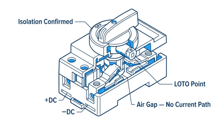
DC surge protection faces unique challenges compared to AC applications due to fundamental differences in current behavior. Alternating current naturally crosses zero voltage twice per electrical cycle—120 times per second on 60Hz systems. This zero crossing naturally extinguishes arcs in protective devices, making AC surge protection relatively straightforward with components that only need to interrupt current during brief zero-current periods.
Direct current maintains constant polarity without zero crossings, creating sustained arcs when protective devices conduct during surge events. These DC arcs don’t naturally extinguish and can continue indefinitely if the protective device can’t actively interrupt current flow. DC SPDs must incorporate enhanced arc extinction mechanisms that AC devices don’t require, making DC-rated SPDs more complex and typically more expensive than equivalent AC protection.
Solar photovoltaic systems operate at DC voltages commonly reaching 600V to 1500V—substantially higher than typical 120/240V AC residential systems. Higher voltages create stronger arcs requiring proportionally greater suppression capabilities. A 1000V DC SPD faces much more severe operating conditions than a 240V AC device, requiring specialized designs and materials to reliably protect equipment over many surge events.
💡 Key Insight: Never use AC-rated SPDs in DC solar applications—they lack the arc extinction capabilities required for DC service and will fail catastrophically. Always verify explicit DC voltage ratings on SPD labeling before installing in photovoltaic systems.
SPDs protect by clamping—limiting—voltage appearing across protected equipment during surge events. Under normal operating conditions, SPDs present extremely high impedance appearing essentially as open circuits. When voltage exceeds the SPD’s threshold level, the device rapidly transitions to low impedance, conducting surge current to ground while maintaining voltage across its terminals at the clamping voltage level.
This voltage clamping prevents excessive voltage from reaching protected equipment. If an inverter can withstand 2000V before insulation breakdown but a lightning surge reaches 10,000V, the SPD must clamp voltage below 2000V. A properly rated SPD might clamp at 1500V—comfortably below equipment limits while staying high enough above normal operating voltage to avoid false activation during normal conditions.
The relationship between normal operating voltage, SPD clamping voltage, and equipment insulation voltage determines protection effectiveness. Ideal SPDs clamp just above normal operating voltage while staying well below equipment withstand voltage. However, physics limits how tightly SPDs can clamp—lower clamping voltages require more sophisticated (expensive) technologies and reduce SPD energy handling capability.
SPD response time critically affects protection quality. Lightning surge voltages rise extremely fast—often reaching peak voltage in microseconds. If SPDs respond slowly, voltage can rise substantially above eventual clamping voltage before the SPD fully conducts. Fast-responding SPDs limit this voltage overshoot, providing better equipment protection than slower devices even when both eventually clamp at the same steady-state voltage.
When SPDs activate during surges, they divert surge current away from protected equipment through an alternate path to ground. The surge current flows from the incoming conductor through the SPD to the grounding electrode system rather than continuing through protected equipment. This current diversion reduces surge energy reaching equipment from potentially destructive levels to safe levels within equipment withstand capabilities.
Effective current diversion requires low-impedance ground connections. SPDs can only divert current if the path to ground offers lower impedance than the path through protected equipment. Long, coiled, or undersized ground conductors introduce impedance that reduces SPD effectiveness by forcing some surge current through equipment despite SPD operation. Proper SPD installation mandates shortest possible ground connections using adequately sized conductors.
| SPD Component | Normal State | During Surge | Function |
|---|---|---|---|
| Protected Equipment | Receives normal voltage | Protected from overvoltage | Load device |
| SPD Elements | High impedance (open) | Low impedance (conducting) | Voltage clamp |
| Ground Path | No current flow | Diverts surge current | Current sink |
The SPD must handle all diverted surge current without damage while simultaneously clamping voltage. This dual requirement—handling high current while maintaining low voltage—represents the fundamental engineering challenge in SPD design. Different protection technologies achieve this balance through different mechanisms, with MOVs and GDTs representing the most common approaches in solar applications.

Metal oxide varistors form the heart of most solar DC SPDs due to their excellent balance of performance, reliability, and cost. MOVs consist of sintered zinc oxide ceramic material containing numerous microscopic grain boundaries that create voltage-dependent resistance. Under normal voltage conditions, MOV grain boundaries present high resistance blocking current flow. When voltage exceeds the MOV’s threshold, the grain boundaries break down allowing current conduction.
The voltage-dependent resistance characteristic gives MOVs their name—”varistor” combines “variable resistor” indicating resistance that changes with applied voltage. MOV resistance decreases dramatically as voltage increases above threshold, creating the clamping action that limits voltage during surges. This behavior occurs naturally through the semiconductor properties of zinc oxide grain boundaries without requiring any external control circuits or triggering mechanisms.
MOV construction involves mixing zinc oxide powder with small amounts of bismuth, cobalt, manganese and other metal oxides, then compressing and sintering the mixture at high temperature. The sintering process fuses the material into a solid ceramic disk with the desired electrical characteristics. Metal electrodes on disk faces provide connection points, with the entire assembly often coated in epoxy or housed in ceramic cases for environmental protection and insulation.
MOV voltage rating depends on disk thickness and the zinc oxide formulation. Thicker disks withstand higher voltages since more grain boundaries exist in series. Energy handling capacity relates to disk diameter—larger diameters dissipate more heat and handle more surge energy before failure. Solar DC SPDs typically use MOV disks 25mm to 40mm diameter for adequate energy handling at 600V to 1500V ratings.
🎯 Pro Tip: MOV voltage ratings drift with temperature—clamping voltage decreases as temperature rises. This thermal coefficient means MOVs clamp tighter when hot, potentially beneficial for protection but also increasing stress on the MOV itself during repeated surge events in hot environments.
MOVs offer several significant advantages making them popular for solar applications. Their fast response time—typically activating within nanoseconds—provides excellent protection against fast-rising lightning transients. MOVs handle moderate to high energy levels adequate for most solar surge protection needs. The technology proves cost-effective, reliable, and well-understood through decades of widespread use in surge protection applications.
MOV clamping voltage remains relatively stable across a wide range of surge currents. Unlike some protection technologies where clamping voltage increases substantially with current, MOVs maintain reasonably consistent clamping throughout their rated current range. This predictable behavior simplifies protection coordination and allows confident equipment protection specification.
However, MOVs suffer from gradual degradation when exposed to repeated surge events or extended operation near their voltage rating. Each surge slightly damages the zinc oxide structure, incrementally reducing the MOV’s voltage threshold. After many surges, the MOV may begin conducting at normal operating voltage, drawing continuous current that generates heat and eventually causes catastrophic failure. This degradation makes MOV service life somewhat unpredictable depending on surge exposure history.
MOV follow current represents another limitation in DC applications. When MOVs clamp during surges, they momentarily conduct high currents. In AC systems, the normal zero-crossing of AC current naturally extinguishes this flow. In DC systems without zero crossings, MOVs may continue conducting after the surge passes if the system can supply sufficient current. Quality DC SPDs incorporate series disconnectors or current-limiting elements managing MOV follow current, but these additions increase cost and complexity.
Gas discharge tubes provide an alternative surge protection technology using ionization of sealed gas to conduct surge current. GDTs consist of two or three electrodes separated by small gaps inside ceramic or glass tubes filled with inert gas—typically argon or a mixture of noble gases. Under normal voltage, the gas remains non-conductive and GDTs present extremely high impedance approaching infinity.
When voltage across GDT electrodes exceeds the gas ionization threshold, the gas breaks down becoming conductive plasma. This ionized gas conducts surge current between electrodes with very low resistance—typically less than 1 ohm when fully ionized. The low resistance allows GDTs to handle extremely high currents while generating minimal voltage drop, making them excellent for high-energy surge protection applications.
After the surge current ceases, the ionized gas quickly recombines returning to its non-conductive state. This self-recovery characteristic means GDTs automatically return to protecting mode after surge events without requiring replacement unless damage occurs. The rapid deionization in AC systems occurs naturally at current zero crossings. In DC systems, the discharge must self-extinguish when surge current falls below the gas’s minimum holding current level.
GDT voltage ratings depend on electrode gap spacing and gas composition. Wider gaps and lower-pressure gas increase breakdown voltage, while narrower gaps and higher pressure reduce it. Solar DC SPDs typically use multi-gap GDTs with three electrodes creating two series discharge gaps, allowing higher voltage ratings from compact packages. These designs commonly achieve 600V to 1500V DC ratings suitable for photovoltaic applications.
GDTs excel at handling very high surge currents—substantially more than MOVs of similar size. Their low conduction voltage drop during surges means less energy dissipation in the protective device and correspondingly higher energy handling capability. GDTs also exhibit minimal degradation from surge exposure, providing consistent performance throughout long service lives even in high-exposure lightning environments.
The extremely high normal-state impedance of GDTs introduces essentially zero loading on protected circuits. No leakage current flows through non-conducting GDTs, unlike MOVs which exhibit small leakage currents that increase with aging. This zero-leakage characteristic proves valuable in some specialized applications where even microampere leakage currents create problems.
However, GDTs suffer several significant limitations affecting their solar SPD applications. Slower response time compared to MOVs—typically microseconds rather than nanoseconds—allows voltage to rise substantially before GDT ionization occurs. This voltage overshoot can exceed equipment withstand limits despite eventual GDT operation. Fast-rising lightning transients may damage equipment before slower GDTs fully activate.
GDT voltage characteristics prove less predictable than MOVs. The breakdown voltage varies with temperature, applied voltage rate-of-rise, and even previous surge history. Wide tolerance ranges mean GDTs from the same manufacturing batch may ionize at voltages varying by ±20% or more. This variability complicates precise protection coordination and makes tight voltage clamping difficult to achieve reliably.
Many premium solar DC SPDs use hybrid designs combining MOVs and GDTs to leverage the advantages of each technology while mitigating their respective limitations. Common hybrid configurations place MOVs and GDTs in series or parallel arrangements coordinating their operation through careful component selection and additional control elements.
Series hybrid designs place a GDT in series with an MOV. The MOV provides fast initial response clamping voltage quickly, while the GDT handles sustained high current after it ionizes. This arrangement protects against both fast-rising transients requiring immediate response and high-energy surges exceeding MOV capability. Series designs require careful coordination ensuring the GDT ionizes before MOV energy limits are exceeded.
Parallel hybrid designs connect MOVs and GDTs across the same line-to-ground path with current-limiting resistors or inductors managing interaction between elements. Fast MOV response handles initial transient voltage rise, then the GDT ionizes and carries majority surge current due to its lower conduction resistance. This configuration provides fast response with high current handling, though proper coordination requires sophisticated design preventing component conflicts.
⚠️ Important: Hybrid SPD designs require expert engineering balancing component characteristics. Improperly coordinated hybrid designs can perform worse than single-technology SPDs if components fight each other during surge events. Specify hybrid SPDs from reputable manufacturers who provide test data demonstrating proper coordination.
Silicon avalanche diode technology represents a third protection approach finding applications in sensitive electronics protection and specialized solar SPD designs. SADs use heavily-doped silicon PN junctions that undergo avalanche breakdown at precise voltages, providing extremely tight voltage clamping and ultra-fast response measured in picoseconds.
SADs offer several advantages including the tightest clamping voltage tolerances of any protection technology—typically ±5% compared to ±10-20% for MOVs and wider for GDTs. This precision allows protection systems to operate closer to equipment voltage limits maximizing efficiency. Ultra-fast response protects against even the fastest-rising transients without voltage overshoot. SADs also prove exceptionally reliable with no degradation from surge exposure over millions of operations.
However, individual SAD devices handle relatively low energy requiring series-parallel arrays for high-voltage, high-energy applications like solar systems. These arrays increase cost and complexity substantially. SADs work best in hybrid designs protecting sensitive circuits downstream from MOV or GDT primary protection stages. Final-stage SAD protection provides tight voltage clamping for delicate electronics after upstream protection reduces surge energy to levels SADs can handle.

Maximum continuous operating voltage represents the highest voltage an SPD can withstand continuously without degradation or false activation. MCOV must exceed the maximum voltage appearing across the SPD under all normal operating conditions including variations from temperature effects, grid voltage fluctuations, and system operational states. Operating SPDs continuously above their MCOV rating causes premature failure through thermal stress or component degradation.
For solar DC applications, MCOV must account for array maximum power point voltage which varies with irradiance and temperature. On sunny days, arrays operate near their rated MPP voltage, while overcast conditions may cause inverters to operate at higher voltages seeking maximum power. The SPD MCOV must exceed these operating voltages with adequate margin—typically 10-20% minimum to ensure reliable operation without false activation.
Temperature affects MCOV ratings differently for various SPD technologies. MOV voltage ratings decrease slightly at elevated temperatures, while GDT breakdown voltages generally increase with temperature. Quality SPD specifications provide MCOV ratings across the full operating temperature range rather than at single arbitrary test temperatures. Verify that SPD MCOV exceeds system voltage at the highest expected operating temperature, not just at standard 25°C.
Voltage protection rating—also called clamping voltage—indicates the maximum voltage appearing across the SPD and protected equipment during surge events. Lower VPR values provide better equipment protection by limiting voltage to safer levels. However, VPR must remain sufficiently above MCOV to prevent false SPD activation during normal operations including voltage transients from legitimate switching events.
SPD manufacturers typically specify VPR at specific test currents—commonly 10kA for residential devices and 20kA for commercial applications. Clamping voltage increases somewhat with surge current, so higher test currents yield higher VPR specifications. When comparing SPDs, ensure VPR comparisons use the same test current methodology—a device showing 1500V VPR at 10kA might exhibit 1700V at 20kA.
The relationship between equipment withstand voltage, SPD clamping voltage, and voltage rise from lead inductance determines overall protection effectiveness. If equipment withstands 2000V, SPD clamps at 1500V, but lead inductance adds 600V overshoot, the effective equipment exposure reaches 2100V—exceeding its withstand capability despite technically adequate SPD clamping. Proper SPD installation with minimal lead length proves as important as SPD VPR specifications.
Nominal discharge current (In) indicates the surge current level an SPD handles repeatedly without damage. SPDs undergo testing with In-level surge currents multiple times—typically 15-20 operations—verifying they survive without degradation or failure. In provides a realistic indication of SPD robustness for normal surge exposure expected during service life.
Maximum discharge current (Imax) represents the highest single surge current an SPD can survive without catastrophic failure. This rating applies to worst-case surge events like nearby lightning strikes that may only occur once in an SPD’s lifetime. Imax typically exceeds In by factors of 2-5 depending on SPD design and technology, reflecting the difference between repeated moderate surges and single extreme events.
For solar applications, select SPDs with In ratings appropriate for expected surge exposure frequency and Imax adequate for lightning zone considerations. Moderate lightning exposure areas might use SPDs rated 20kA In / 40kA Imax, while high-exposure regions benefit from 40kA In / 80-100kA Imax specifications. The higher ratings cost more but provide necessary protection margins in severe environments.
🎯 Pro Tip: Don’t confuse SPD current ratings with overcurrent protection device ratings. A 20kA SPD refers to surge current handling, not continuous or short-circuit current. SPD circuits still need fuses or breakers—typically 15-20A—protecting against sustained faults if SPDs fail short-circuit.
Proper SPD voltage rating selection requires understanding three critical voltage levels: system nominal voltage, maximum power point voltage, and open-circuit voltage. Nominal voltage (like 600V or 1000V) represents typical operating voltage but doesn’t capture the voltage range SPDs must accommodate. Maximum power point voltage varies with temperature and irradiance but represents the voltage where inverters normally operate.
Open-circuit voltage defines the upper voltage limit when arrays operate with no load current flow. This condition occurs during grid outages, early morning before inverters start, or whenever inverters disconnect from arrays. VOC varies significantly with temperature—cold weather increases VOC substantially above rated values. NEC 690.7 requires calculating maximum VOC accounting for lowest expected ambient temperature, often yielding voltages 20% above rated.
SPD maximum continuous operating voltage (MCOV) must exceed system maximum power point voltage, while voltage protection rating must stay below equipment insulation withstand voltage. A 1000V nominal system might have 850V MPP voltage and 1200V maximum VOC. Appropriate SPD specifications might be 1000V MCOV / 1500V VPR, positioning the SPD to handle normal operation without false activation while clamping below equipment limits during surges.
SPD requirements vary dramatically based on installation position within the PV system. Array combiners and main DC disconnects face highest surge energy exposure from direct or nearby lightning strikes, requiring Type 1 SPDs with high current ratings—commonly 40-100kA depending on lightning exposure. These locations benefit from GDT or hybrid technologies providing maximum energy handling.
Inverter DC input terminals require precise voltage clamping protecting sensitive semiconductors but face lower surge energy after upstream conductor impedance and primary SPDs attenuate threats. Type 2 SPDs with 15-20kA ratings typically suffice at inverter locations. MOV technology works well here, providing fast response and tight clamping voltage protecting delicate electronics. Multiple inverters each need individual SPDs rather than collective protection.
Equipment DC input terminals need individual protection even when upstream SPDs exist at combiners or disconnects. The conductor runs between protection stages introduce voltage rise during fast transients that can exceed equipment withstand limits despite upstream SPD operation. Terminal-level SPDs provide localized clamping immediately at equipment connections, preventing lead-inductance voltage rise from defeating protection.
IEC 61643-31 establishes specific requirements for SPDs in photovoltaic systems, addressing the unique challenges of DC surge protection at high voltages. This standard defines testing procedures, performance classifications, and marking requirements ensuring SPDs perform reliably in solar applications. SPDs certified to IEC 61643-31 have undergone rigorous testing simulating lightning and switching surge exposure PV systems experience.
The standard establishes SPD classifications (Type 1, 2, and 3) based on tested current waveforms and energy handling capabilities. Type 1 testing uses 10/350μs current waveforms representing direct lightning current, while Type 2 testing uses 8/20μs waveforms for induced surges. These different waveforms contain dramatically different energy content—10/350μs waveforms deliver far more energy than 8/20μs at the same peak current, making Type 1 testing much more stringent.
Temperature cycling tests verify SPDs function across -40°C to +85°C ranges typical of outdoor solar installations. Operational testing at temperature extremes ensures SPDs don’t falsely activate in cold weather (when system voltages rise) or fail prematurely in hot conditions. Humidity testing confirms SPDs maintain insulation integrity and don’t degrade from moisture exposure in condensing environments.
UL 1449 provides North American SPD testing and listing requirements covering both AC and DC applications. The fourth edition (UL 1449 Ed.4) includes enhanced requirements for DC SPDs used in photovoltaic systems, reflecting the rapid growth of solar installations. SPDs listed to UL 1449 have passed tests verifying electrical performance, fire safety, and reliable operation under specified conditions.
Voltage protection rating testing measures actual clamping voltage at standardized current levels using specific waveforms. These tests verify that SPDs limit voltage to their claimed VPR specifications. UL 1449 also requires temporary overvoltage (TOV) testing where SPDs must withstand sustained overvoltages that might occur from ground faults or system malfunctions without catching fire or creating shock hazards.
Short-circuit current rating (SCCR) testing verifies SPDs can withstand the maximum available fault current at their installation location without exploding or creating arc flash hazards. This safety testing proves critical since SPDs failing short-circuit can create extremely dangerous conditions with available currents reaching tens of thousands of amperes in solar installations. Only SPDs successfully passing SCCR testing receive UL listing.
Many installers believe that installing SPDs at every possible location provides maximum protection regardless of SPD ratings or coordination. However, improperly selected or placed SPDs can actually worsen protection by creating ground loops, introducing noise, or causing SPD coordination failures where devices fight each other during surge events.
Effective protection uses appropriate SPD types at strategic locations rather than maximum quantity. A well-designed system might have Type 1 SPDs at array combiners and main disconnect plus Type 2 SPDs at each inverter—totaling four to six SPDs for a typical residential installation. Installing additional SPDs at every junction box or disconnect doesn’t improve protection and adds unnecessary cost while potentially creating problems.
The quality and proper installation of fewer SPDs outweighs quantity of mediocre devices poorly placed. Two properly rated SPDs with correct grounding and minimal lead lengths provide superior protection to a dozen SPDs with inadequate ratings, long ground connections, or improper coordination. Focus on proper SPD specification and installation rather than simply maximizing SPD count.
SPDs form only one component of comprehensive lightning protection, not standalone solutions protecting against all lightning threats. SPDs protect against overvoltages appearing on electrical conductors but don’t prevent direct lightning attachment to equipment or structures. Complete lightning protection requires external lightning protection systems (air terminals, down conductors, grounding electrodes) working in conjunction with SPD protection.
Lightning striking arrays can destroy modules, racking, and structural components through mechanical forces, extreme heat, and shockwaves regardless of electrical protection. SPDs can’t prevent this damage—they only protect electrical equipment from surge currents and voltages propagating through conductors. Locations with extreme lightning exposure may need external LPS intercepting strikes before they reach PV equipment.
Proper grounding and bonding prove equally important to SPD protection. Even the best SPDs fail to protect equipment adequately when grounding connections introduce excessive impedance or multiple ground electrodes create circulating currents. Comprehensive protection integrates SPDs, external lightning protection, proper grounding, and equipment placement in coordinated systems addressing all threat vectors.
Some installers assume SPDs with higher voltage ratings provide better protection, selecting 1500V devices for 600V systems reasoning “more is better.” However, excessively high voltage ratings can actually reduce protection effectiveness. SPD clamping voltage roughly scales with voltage rating—1500V SPDs typically clamp around 2500-3000V while 600V devices clamp at 1200-1500V. Using overrated SPDs leaves equipment exposed to unnecessarily high clamping voltages.
Proper SPD rating selection matches system voltage requirements with appropriate safety margin. For a 600V nominal system with 720V maximum VOC, select SPDs rated 800-1000V DC providing adequate margin above system voltage while minimizing clamping voltage. The 1000V rating offers comfortable margin, while a 1500V rating provides no benefit and worse protection through higher clamping.
MCOV provides the correct selection criterion—not the SPD’s maximum rated voltage. Select SPDs where MCOV exceeds system maximum power point voltage by 10-20%, then verify VPR stays well below equipment withstand voltage. This approach ensures SPDs won’t falsely activate during normal operation while providing optimal clamping during surge events.

SPD stands for Surge Protection Device—equipment that limits transient overvoltages and diverts surge currents protecting solar photovoltaic equipment from lightning and switching transients. The term “SPD” standardized across international electrical codes and standards, replacing older terms like surge suppressor or TVSS (transient voltage surge suppressor). DC SPDs specifically designed for solar applications must carry DC voltage ratings appropriate for system voltage and undergo testing per IEC 61643-31 or UL 1449 standards addressing photovoltaic surge protection requirements.
Metal oxide varistors (MOVs) use voltage-dependent zinc oxide ceramic that conducts when voltage exceeds threshold, providing fast response (nanoseconds) and predictable clamping suitable for most solar applications. Gas discharge tubes (GDTs) use ionizing gas to conduct surge current, offering very high current handling and minimal degradation but slower response (microseconds). MOVs work well for final equipment protection requiring fast response, while GDTs excel at primary protection handling high-energy surges at array origins. Many premium SPDs use hybrid designs combining both technologies.
NEC 690.35(A) mandates DC SPDs when circuit conductors exceed 2 meters (6.6 feet) from PV array to equipment, covering virtually all solar installations except micro-inverter systems. Beyond code requirements, any system with exposed rooftop arrays, conductor runs through buildings, or valuable equipment justifies SPD protection. Lightning damage costs thousands in equipment replacement plus lost production—SPD protection costing hundreds proves worthwhile insurance. High lightning exposure regions especially benefit from comprehensive SPD protection at multiple system locations.
No—never use AC-only SPDs in DC solar applications. AC surge protection relies on natural current zero-crossings to extinguish arcs that DC systems lack. AC-rated SPDs will fail catastrophically in DC service, potentially causing fires or creating shock hazards. Always verify explicit DC voltage ratings on SPD labels before installing in photovoltaic systems. Quality DC SPDs carry IEC 61643-31 or UL 1449 listings specifically addressing DC surge protection requirements including enhanced arc extinction for sustained DC current.
Quality SPDs with status indication should be inspected quarterly in high-exposure locations or annually elsewhere, replacing any showing failure indications. SPDs without visual indicators benefit from proactive replacement every 5-7 years in high lightning exposure regions or 10+ years in moderate areas. Extreme exposure locations or systems experiencing multiple lightning strike events may require more frequent replacement. Replace SPDs immediately after nearby lightning strikes even without visible damage—the stress may have degraded components below specifications making them unable to protect against subsequent surges.
A 1000V nominal DC system requires calculating maximum open-circuit voltage with temperature correction per NEC 690.7—typically yielding 1150-1200V. Select SPDs where maximum continuous operating voltage (MCOV) exceeds your maximum power point voltage by 10-20%—commonly 1000-1100V MCOV for 1000V systems. The SPD overall voltage rating should be 1200-1500V DC providing margin above maximum VOC. Verify voltage protection rating (VPR) stays below equipment withstand voltage—typically 2000V for inverters. This balances preventing false activation during normal operation while providing adequate surge clamping.
Yes, MOVs exhibit gradual degradation from continuous voltage stress even without major surge events. Operating near maximum continuous operating voltage (MCOV) accelerates degradation as does elevated temperature. Each small surge or voltage transient incrementally damages the zinc oxide structure, slowly reducing voltage threshold. Quality SPDs include thermal disconnectors or fuses isolating failed MOVs before fire hazards develop. This degradation makes periodic inspection and proactive replacement important—SPDs lose effectiveness before showing obvious failure signs. Proper MCOV selection with adequate margin above normal operating voltage minimizes degradation rate extending service life.
Understanding DC SPD fundamentals provides foundation for proper surge protection system design and installation.
Learn more about SPD applications and installation in our comprehensive guides:
– DC SPD for Solar Systems – Complete SPD selection and coordination
– Solar Lightning Protection – Comprehensive protection system design
– DC Circuit Protection – Coordinating SPDs with overcurrent protection
– PV System Grounding – Proper grounding for SPD effectiveness
Ready to implement effective DC SPD protection for your solar installation? Our technical team at SYNODE provides expert guidance on surge protection device selection, MOV versus GDT technology decisions, and proper installation practices. We help ensure comprehensive protection meeting NEC 690.35 requirements while optimizing protection effectiveness and system economics.
Contact our application engineers for DC SPD specification assistance and lightning protection system design services.
Last Updated: October 2025
Author: SYNODE Technical Team
Reviewed by: Electrical Engineering Department