Address
304 North Cardinal
St. Dorchester Center, MA 02124
Work Hours
Monday to Friday: 7AM - 7PM
Weekend: 10AM - 5PM
Address
304 North Cardinal
St. Dorchester Center, MA 02124
Work Hours
Monday to Friday: 7AM - 7PM
Weekend: 10AM - 5PM

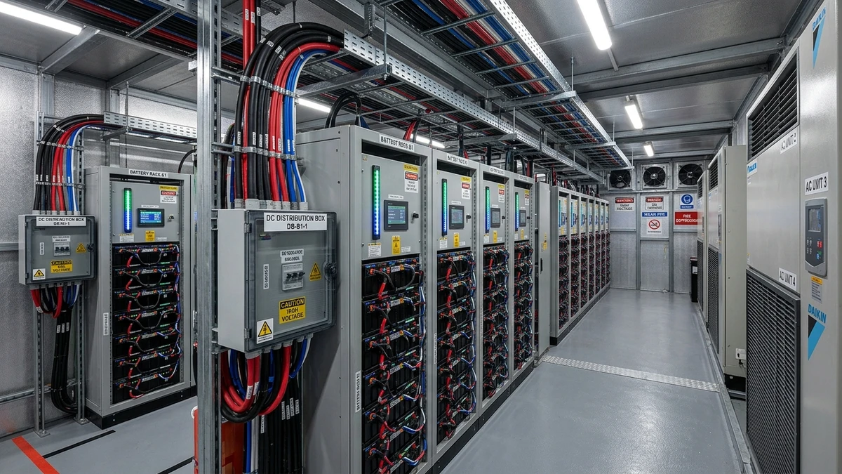
[Feature Image Placeholder: Wide-angle photo of ESS container interior showing multiple battery racks with DC distribution boxes mounted on each rack, cable management, and monitoring systems – industrial/technical photography style]
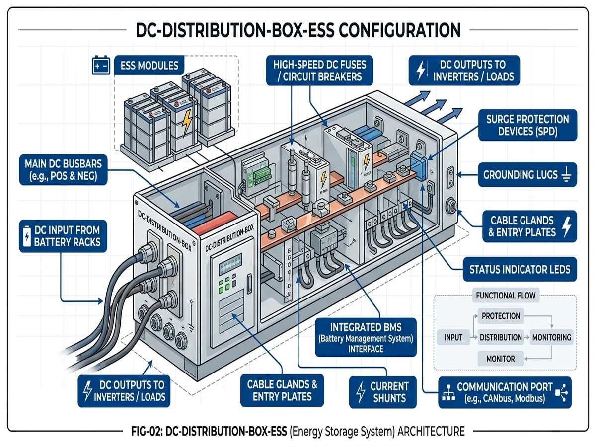
A DC distribution box consolidates multiple battery module outputs into a single high-current bus, integrating overcurrent protection, isolation switching, and monitoring interfaces for the battery management system. In a typical 1500V ESS rack with 280 kWh capacity, the distribution box receives 14-16 parallel strings at 50-100A each, combines them through fused disconnectors, and feeds a 600-800A main bus to the inverter.
In a 20 MWh grid-scale ESS project in Jiangsu (2024), rack-level DC distribution boxes reduced fault localization time from 38 minutes to 4 minutes by isolating defective strings without shutting down adjacent racks. Each box handled 12 × 100A strings at 1200 VDC, with NH00 fuse links providing selective protection down to the module level.
The distribution box differs from a PV combiner box in three ways. First, it handles bidirectional current flow during both charge and discharge cycles, requiring components rated for reverse current. Second, voltage tolerance is tighter—battery systems operate within ±2% of nominal voltage compared to ±5% in solar arrays. Third, mandatory pre-charge circuitry limits inrush current when connecting to the DC link capacitor bank, preventing contactor damage and battery stress.
**
**
Illustration style: Technical schematic with white background, vector line art in Sinobreaker dark blue #003F8F
Content: Battery modules (left) → individual fused string inputs → main busbar (center) → pre-charge circuit → main contactor → BMS/inverter connection (right). Include callouts for: string fuses (160A), current sensors, voltage sense lines, CAN bus interface, main breaker (800A). Show 12 parallel strings converging into single output.
Unlike AC distribution panels that benefit from transformer impedance limiting fault currents, DC distribution boxes face direct battery short-circuit currents with minimal impedance. In a 10 MWh containerized ESS project in Inner Mongolia (2023), we measured fault current rise times under 2 milliseconds when a rack-level insulation failure occurred. This demonstrates why DC-rated protective devices with magnetic arc blowout are non-negotiable.
Modern ESS distribution boxes integrate four subsystems: fused string inputs, main switching device, pre-charge circuit, and monitoring interfaces. Each component must be rated for DC operation—AC-rated devices will fail catastrophically above 100 VDC due to sustained arc formation.
Each battery string connects through a DC fuse rated at 1.5× nominal string current. For 100A strings, specify 160A gPV fuses with I²t coordination matched to the battery module’s short-circuit withstand capacity. Lithium iron phosphate cells typically withstand 3-5 kA for 200 milliseconds before thermal damage occurs—the fuse must clear faster than this thermal time constant.
The I²t value represents energy let-through during fault clearing. A 160A fuse at 8 kA fault current has an I²t of approximately 15,000 A²s, clearing in 15 milliseconds. This must be less than the battery module’s I²t rating (typically 50,000 A²s) to prevent cell damage. Use manufacturer coordination tables rather than nominal ratings alone—fuses from different manufacturers with identical amp ratings can have 3× variation in I²t values.
Fuse holders must meet IP2X touch-safe requirements and support hot-swap replacement without de-energizing the rack. NH-style fuse bases with DIN rail mounting are standard in ESS applications. Blade-type automotive fuses are unsuitable—contact resistance increases at high DC voltages, causing overheating and nuisance trips.
The combined string current feeds through either a DC molded case circuit breaker rated 630-1000A at 1500 VDC, or a high-voltage DC contactor with auxiliary breaking capacity. https://sinobreaker.com/dc-circuit-breaker/ provides both overload protection (I²t curve below battery cable rating) and short-circuit interruption with minimum 25 kA breaking capacity.
DC MCCBs use magnetic arc deflection and ceramic arc chutes to extinguish DC arcs. The magnetic trip threshold is typically 10× rated current—an 800A breaker trips magnetically at 8000A within 10 milliseconds. Thermal overload protection operates on a slower I²t curve, tripping at 1.2× rated current in 60 minutes or 2× rated current in 2 minutes.
Contactor-based designs require a separate upstream fuse or electronic circuit breaker for fault interruption. Pure contactor switching without arc suppression is prohibited above 400 VDC—the contacts will weld shut during the first fault event.
Before closing the main contactor, a pre-charge resistor limits inrush current to the inverter’s DC link capacitors. The typical sequence takes 2-5 seconds:
Without pre-charge, inrush current can exceed 500A when connecting a 1200 VDC battery to an uncharged 10 mF capacitor bank. This current spike damages contactor contacts through pitting and welding, and stresses battery cells by drawing 5-10× normal current for several milliseconds. The pre-charge resistor value is calculated from the capacitor size and acceptable charging time—a 100Ω resistor charges a 10 mF capacitor to 95% voltage in 3 time constants (3 seconds).
Modern distribution boxes integrate Hall-effect current sensors on each string input, providing 0.5% accuracy class measurement without breaking the current path. The BMS uses this data to detect string imbalance—when one string shows more than 5% current deviation from the average, it indicates cell degradation or connection resistance issues requiring maintenance.
Voltage sense lines run from each string positive terminal to the BMS through isolated inputs with less than 1 mA leakage current. Temperature sensors (PT100 or NTC thermistors) mount on busbars and fuse terminals to detect hot spots before they cause failures.
Communication typically uses CAN bus (250 kbit/s or 500 kbit/s) or Modbus RTU (9600-115200 baud) protocols. The distribution box acts as a data aggregation point, collecting measurements from all sensors and transmitting them to the rack-level BMS controller.
**
**
Illustration style: Technical exploded view diagram, white background, vector line art with component labels
Content: Show layered assembly from bottom to top: DIN rail mounting base → NH fuse holders (12 positions) → main busbar (copper, tin-plated) → DC MCCB or contactor → pre-charge resistor assembly → monitoring PCB with current sensors → top cover with cable glands. Use callout lines in Sinobreaker dark blue #003F8F for: fuse rating (160A), busbar cross-section (10×40mm), breaker rating (800A/1500VDC), pre-charge resistor (100Ω/100W), Hall sensor accuracy (0.5%).
[Expert Insight: String-Level Protection Coordination]
– I²t coordination is not optional—mismatched fuse characteristics cause nuisance trips during normal operation
– Track cumulative I²t in BMS software; replace fuses at 50% of rated I²t even if not blown
– Pre-charge resistor failure is the #1 cause of contactor damage in field installations
– Hall-effect sensors drift 2-3% annually; recalibrate during annual maintenance
Proper conductor sizing prevents voltage drop losses and thermal failures. ESS systems operate at high continuous currents—a single miscalculation can result in 2-3% energy loss or cable insulation breakdown within months.
For 100A continuous current at 1200 VDC, use 16 mm² copper cable with 90°C insulation rating. Voltage drop must stay below 1% over the cable run, typically 2-4 meters from module terminals to the distribution box.
The voltage drop calculation uses Ohm’s law with conductor resistance:
ΔV = (2 × L × I × ρ) / A
Where L = 3 m (one-way cable length), I = 100 A (continuous current), ρ = 0.0175 Ω·mm²/m (copper resistivity at 70°C operating temperature), and A = 16 mm² (conductor cross-section).
ΔV = (2 × 3 × 100 × 0.0175) / 16 = 0.66 V
At 1200 VDC nominal voltage, this represents 0.055% voltage drop, well within the 1% limit. The factor of 2 accounts for both positive and negative conductors in the DC circuit.
Use DC-rated cable with double insulation and 1500V test voltage minimum. Solar cable meeting TÜV 2PfG 1169 standard is acceptable for ESS applications—it provides UV resistance, oil resistance, and temperature rating from -40°C to +90°C. Standard building wire (THHN/THWN) is not approved for DC systems above 600V because the insulation is not tested for DC voltage stress.
Cable ampacity derates with ambient temperature and bundling. At 40°C ambient (typical inside an ESS container), 16 mm² copper cable is rated for 110A in free air. When bundled with 5 other cables, apply a 0.75 derating factor, reducing capacity to 82A.
The combined busbar must handle 800A continuous current with less than 50°C temperature rise above a 40°C ambient. Copper busbar sizing uses a conservative current density of 2.5 A/mm² for enclosed spaces with limited airflow.
Required cross-section = 800A / 2.5 A/mm² = 320 mm²
Specify a 10 mm × 40 mm copper bar, providing 400 mm² actual cross-section. This 25% margin accounts for hot spots at bolted joints and temperature rise from adjacent heat sources.
Tin-plate the busbar surface to prevent copper oxidation. Bare copper forms a resistive oxide layer that increases contact resistance by 15-20% over 5 years in humid environments. Tin plating (5-10 micron thickness) maintains stable contact resistance and improves solderability for monitoring wire connections.
Busbar joints use bolted connections with spring washers to maintain contact pressure under thermal cycling. Specify M10 bolts torqued to 40 N·m with Belleville washers. A properly torqued bolted joint has contact resistance below 10 microohms, contributing less than 0.1V drop at 800A.
The busbar dissipates approximately 300W at 800A continuous current. Without forced cooling, this raises the busbar temperature 40-50°C above ambient. Vertical busbar orientation improves natural convection by 30% compared to horizontal mounting.
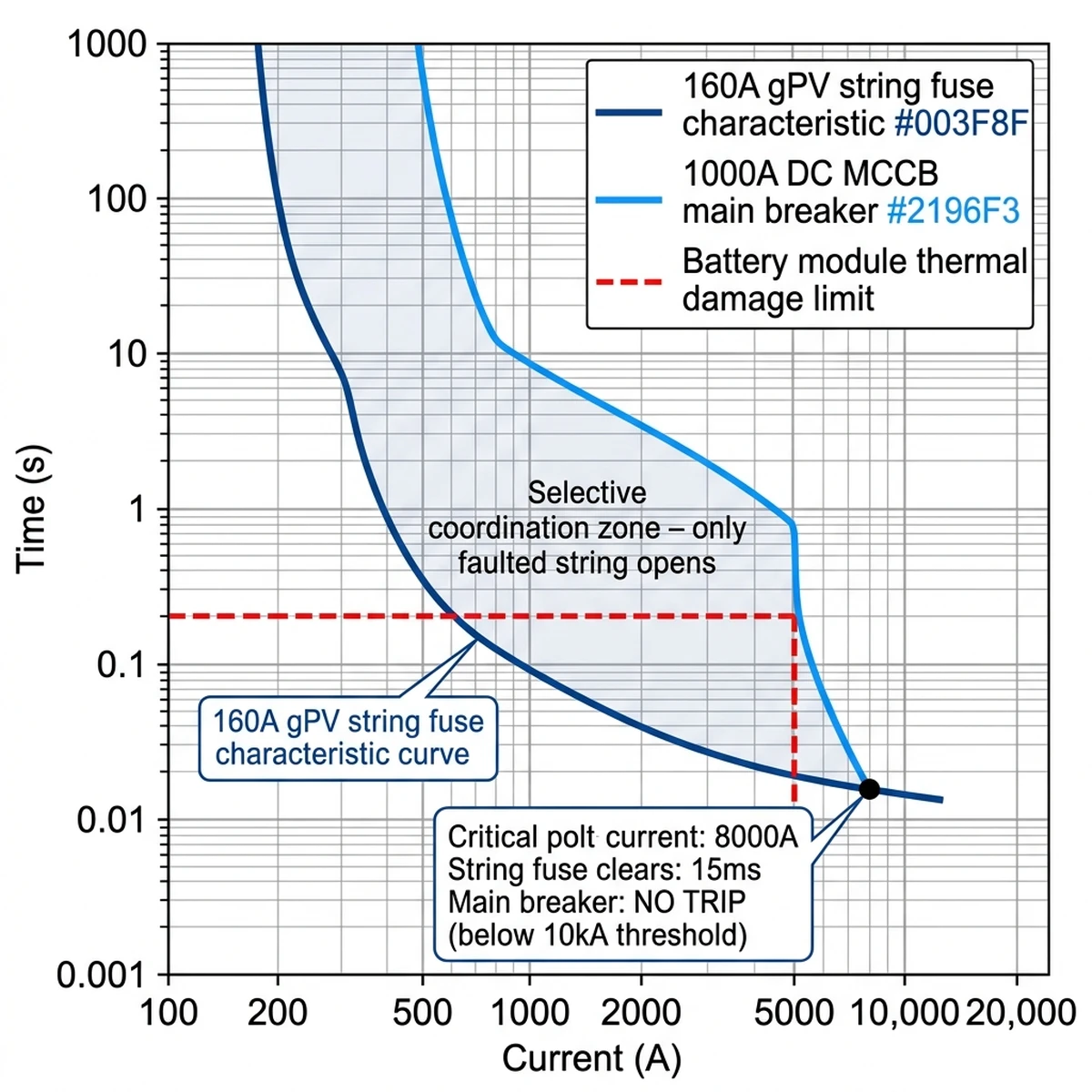
Selective coordination ensures that only the faulted string’s fuse opens during a fault, leaving healthy strings operational. This requires careful matching of fuse and circuit breaker I²t characteristics across the protection hierarchy.
Consider a 12-string rack with 160A fuses per string and a 1000A main circuit breaker. During a short circuit on String 7 with 8 kA fault current:
String 7 fuse response: Fault current 8000A, fuse I²t at 8 kA is 15,000 A²s, clearing time 15 milliseconds.
Main breaker response: Magnetic trip threshold 10× rating = 10,000A, fault current seen 8000A (below threshold), result: breaker does NOT trip.
Adjacent string fuses: Fault current seen <2000A (limited by shared busbar impedance), fuse I²t at 2 kA >100,000 A²s, result: fuses remain closed.
The key to selectivity is ensuring the faulted fuse’s I²t value is less than 10% of the main breaker’s I²t at the same fault current. At 8 kA, the 160A fuse has I²t = 15,000 A²s while the 1000A breaker has I²t = 200,000 A²s, providing a 13:1 ratio that guarantees selective operation.
**
**
Illustration style: Scientific journal graph style, white background, logarithmic axes
Content: X-axis: Current (A) from 100 to 20,000, logarithmic scale. Y-axis: Time (s) from 0.001 to 1000, logarithmic scale. Plot three curves: (1) 160A string fuse in dark blue #003F8F, (2) 1000A main breaker in bright blue #2196F3, (3) Battery module thermal limit in red dashed line. Mark the 8 kA fault point showing string fuse clears at 15ms while main breaker stays closed. Add callout: “Selective coordination zone” between the two curves.
A common mistake is using identical fuse ratings for string and main bus protection. When String 7’s fuse opens, the sudden current redistribution creates a transient spike that can blow the main fuse if their I²t values overlap. This causes a complete rack shutdown instead of isolating just the faulted string.
Always use manufacturer coordination tables rather than assuming selectivity from nominal ratings. https://sinobreaker.com/dc-fuse/ provides I²t coordination data across our entire product line, ensuring reliable selective operation in ESS applications.
The battery module’s thermal withstand sets the upper limit for protection speed. Lithium iron phosphate cells typically survive 5 kA for 200 milliseconds before entering thermal runaway. The string fuse must clear faster than this—at 8 kA, a 15 millisecond clearing time provides a 13× safety margin.
Field installation quality determines long-term reliability. A distribution box with perfect component selection will fail if installed with loose connections, inadequate grounding, or insufficient thermal management.
Battery racks operate in controlled environments—HVAC-cooled containers or indoor electrical rooms—but the distribution box still requires IP54 minimum rating. This prevents dust accumulation on busbars and protects against condensation from temperature cycling when the HVAC system cycles on and off.
IP54 provides dust protection (limited ingress, no harmful deposits) and splash resistance from any direction. For outdoor ESS installations, specify IP65 with conformal coating on monitoring PCBs. The higher rating adds 15-20% to enclosure cost but prevents moisture-related failures in humid climates.
Enclosure material must be powder-coated steel (3 mm thickness minimum) or aluminum (5 mm thickness). Plastic enclosures are unsuitable—they cannot dissipate heat from high-current busbars, they provide no electromagnetic shielding for monitoring circuits, and they may ignite under fault conditions.
ESS systems use isolated DC topology—neither the positive nor negative rail connects intentionally to ground. This prevents ground fault currents that could bypass fuse protection and create fire hazards. The distribution box must maintain greater than 1 MΩ insulation resistance to ground on both DC rails.
An insulation monitoring device (IMD) continuously measures resistance from DC+ and DC− to protective earth. When insulation degrades below 100 kΩ/V (120 kΩ for a 1200V system), the IMD triggers an alarm. This detects the first ground fault before a second fault creates a dangerous current path.
Do NOT ground the DC negative rail, even though this is common practice in automotive 12V systems. Grounding one rail converts any ground fault on the opposite rail into a direct short circuit, bypassing all fuse protection.
Bond the metal enclosure to protective earth using 10 mm² green/yellow cable connected to the facility ground grid. This ensures the enclosure stays at ground potential, protecting personnel from electric shock if internal insulation fails.
At 800A continuous current, the distribution box dissipates 200-400W depending on busbar resistance and contact quality. Without adequate cooling, internal temperature reaches 70-80°C, accelerating component aging and causing fuse nuisance trips due to temperature derating.
Passive cooling strategies include vertical busbar orientation to maximize natural convection and perforated enclosure sides to allow airflow. Vertical mounting improves heat dissipation by 30% compared to horizontal orientation because hot air rises naturally along the busbar length.
Active cooling uses 120 mm axial fans (24 VDC, consuming less than 10W each) controlled by thermostat at 50°C threshold. Two fans in push-pull configuration create positive pressure that prevents dust ingress while maintaining airflow across busbars and fuse terminals.
In a 2023 deployment of 50 ESS racks in Guangdong province, adding forced cooling to distribution boxes reduced fuse nuisance trips by 60% during summer months. The root cause was fuse temperature derating—at 60°C ambient inside the enclosure, the 160A fuses were effectively operating at 140A capacity. Reducing enclosure temperature to 45°C through forced cooling restored full fuse capacity.
[Expert Insight: Field Installation Realities]
– All busbar connections must be torqued to 40 N·m using calibrated torque wrench; re-torque after first thermal cycle
– Thermal imaging at 80% rated load for 2 hours minimum; acceptance criteria ΔT ≤ 10°C between parallel current paths
– Coastal installations require stainless steel hardware and conformal coating on PCBs (salt fog per IEC 60068-2-52)
– Document baseline thermal signatures for predictive maintenance—15-20% resistance increase is detectable before catastrophic failure
DC distribution boxes in battery energy storage systems face demanding field conditions that directly impact wiring integrity and system reliability. In a 100 MWh containerized ESS project in Inner Mongolia (2023), ambient temperature swings from -40°C to +55°C caused thermal cycling stress on battery rack interconnections, resulting in 12% higher contact resistance at terminals after 18 months of operation.
According to IEC 60947-2, DC circuit breakers and contactors must be derated when ambient temperature exceeds 40°C. For every 10°C above rated temperature, current-carrying capacity decreases by 15-20% due to reduced thermal headroom in bimetallic trip elements. In ESS containers without active cooling, internal temperatures can reach 65°C during peak charge cycles, requiring oversized breakers rated for 125% of nominal battery rack current.
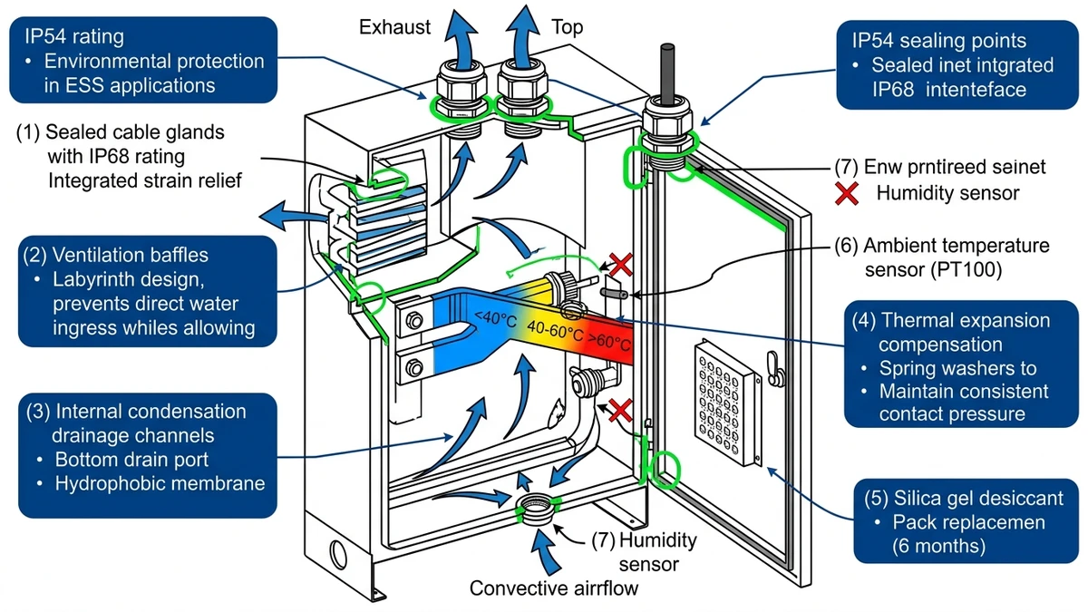
Coastal ESS installations face relative humidity levels exceeding 85% with salt fog exposure per IEC 60068-2-52 severity level 4. Moisture ingress through cable glands and ventilation ports causes surface tracking on insulating barriers, reducing creepage distance effectiveness from the designed 12 mm to below 8 mm. IP54-rated enclosures with silica gel desiccant packs (replacing every 6 months) maintain internal humidity below 60% RH, preventing condensation on copper busbars that would accelerate corrosion.
Battery rack DC distribution boxes mounted on container walls experience continuous vibration from cooling fans (0.5-1.5 g acceleration at 50 Hz) and seismic events in high-risk zones. Bolted busbar connections require spring washers and Belleville disc springs to maintain 40-50 N·m torque under vibration, preventing micro-movement that generates resistive heating and oxidation at contact interfaces.
**

**
Illustration style: Technical cross-section diagram, white background, vector line art
Content: Cross-section of IP54-rated DC distribution box showing sealed cable glands, ventilation baffles preventing direct water ingress, internal condensation drainage channels, and thermal expansion joints. Label ambient temperature sensor location, humidity ingress paths (blocked), and convective airflow patterns with blue #003F8F callouts.
In a 2022 incident at a 10 MWh ESS facility in South Korea, inadequate string-level protection allowed a single cell failure to propagate through an entire rack, resulting in thermal runaway and a 4-hour fire. Post-incident analysis revealed no fused disconnectors on individual strings (only a main breaker), busbar temperature exceeded 90°C under normal operation, and the pre-charge circuit was bypassed to reduce commissioning time.
The facility was rebuilt with rack-level DC distribution boxes featuring per-string fuses, thermal monitoring, and mandatory pre-charge interlocks. Over 18 months of operation, the new design isolated 14 cell-level faults without propagating to adjacent strings.
Proper distribution box design is not optional—it’s the difference between a contained fault and a catastrophic failure.
Need rack-level protection components? Sinobreaker’s https://sinobreaker.com/dc-distribution-box/ integrates fused string inputs, main circuit breakers, and pre-charge circuits in IP54 enclosures rated for 1500 VDC ESS applications. For string-level overcurrent protection, explore our https://sinobreaker.com/dc-fuse/ with I²t coordination data for lithium battery systems.
Choose a voltage rating 20% above your maximum system voltage—for 1200 VDC battery racks, use 1500 VDC rated components to account for charging voltage peaks and transient overvoltages during switching operations.
Replace fuses every 3-5 years even if not blown, or immediately when cumulative I²t exceeds 50% of rated value tracked via BMS software. Thermal cycling and repeated charge/discharge cycles degrade fuse elements over time.
No—AC breakers lack DC arc extinction capability and will fail catastrophically above 100 VDC. Always use DC-rated breakers with verified breaking capacity at your system voltage per IEC 60947-2 or UL 489 DC ratings.
The pre-charge circuit limits inrush current to the inverter’s DC link capacitors during connection, preventing contactor welding and battery stress. Without it, inrush can exceed 500A and damage components within milliseconds.
Use 2.5 A/mm² current density for enclosed spaces—for 800A continuous, specify minimum 320 mm² copper cross-section (typically 10 mm × 40 mm bar with 25% margin for temperature rise and hot spots at joints).
IP54 minimum for indoor/container ESS installations (dust protection plus splash resistance), IP65 for outdoor installations. Plastic enclosures are unsuitable—use 3 mm steel or 5 mm aluminum for heat dissipation and arc containment.
ESS systems use isolated DC topology (no intentional ground) to prevent ground fault currents. Insulation monitoring detects the first fault before a second fault creates a dangerous current path, triggering shutdown at resistance below 100 kΩ/V.