Dirección
304 North Cardinal
Dorchester Center, MA 02124
Horas de trabajo
De lunes a viernes: de 7.00 a 19.00 horas
Fin de semana: 10.00 A 17.00 HORAS
Dirección
304 North Cardinal
Dorchester Center, MA 02124
Horas de trabajo
De lunes a viernes: de 7.00 a 19.00 horas
Fin de semana: 10.00 A 17.00 HORAS


Comprender los procedimientos adecuados del diagrama de cableado de los SPD de CC garantiza una protección eficaz contra sobretensiones, al tiempo que se mantiene el cumplimiento de los códigos y la seguridad del sistema. Esta completa guía de instalación proporciona diagramas de cableado detallados, métodos de conexión a tierra y procedimientos paso a paso para instalar dispositivos de protección contra sobretensiones en sistemas solares fotovoltaicos. Tanto si realiza el cableado de los SPD a nivel de cadena, cajas combinadoras o entradas de inversor, seguir estos métodos probados garantiza un rendimiento fiable de la protección.
El cableado incorrecto de los SPD representa uno de los defectos de instalación más comunes que se detectan durante las inspecciones eléctricas. Los cables de tierra cortos, el dimensionamiento incorrecto de los conductores y las malas prácticas de terminación reducen drásticamente la eficacia de los SPD o crean infracciones del código. Esta guía elimina las conjeturas sobre el cableado al proporcionar diagramas claros y procedimientos verificados para el cumplimiento del NEC.
Antes de comenzar la instalación del SPD, revise minuciosamente los planos eléctricos del sistema para identificar el tendido de los conductores de CC, los niveles de tensión y la infraestructura de puesta a tierra existente. Compruebe que los modelos de SPD especificados coinciden con la tensión de CC real del sistema (600 V, 1.000 V o 1.500 V nominal) y que los valores nominales de corriente continua superan la corriente de cortocircuito de la cadena en los márgenes de seguridad requeridos. Confirme que los tamaños de la caja del combinador o del inversor se adaptan a los SPD seleccionados sin sobrecargarlos.
Identifique las trayectorias existentes del conductor de puesta a tierra del equipo (EGC) y las conexiones de enlace con las que se integrará la puesta a tierra del SPD. Localizar el punto de conexión del electrodo de puesta a tierra más cercano donde terminarán los cables de tierra del SPD. Medir las distancias desde las ubicaciones planificadas del SPD hasta los puntos de conexión a tierra para determinar las longitudes de conductor necesarias y evitar una longitud excesiva del cable de tierra que degrade el rendimiento del SPD.
Revise los requisitos de la autoridad local competente (AHJ) para la instalación de SPD más allá de los mínimos NEC. Algunas jurisdicciones exigen ubicaciones específicas para los SPD, requieren dispositivos de protección adicionales o especifican métodos de cableado concretos. Obtener una aclaración de la AHJ antes de la instalación evita costosas repeticiones cuando los inspectores identifican requisitos específicos de la jurisdicción.
Herramientas de instalación:
- Pelacables aptos para el tamaño de los conductores que se van a terminar
- Destornillador dinamométrico o llave calibrada según las especificaciones del terminal SPD
- Multímetro capaz de medir una tensión continua de 1500 V como mínimo
- Impresora de etiquetas para la identificación permanente de conductores y SPD
- Cinta adhesiva para pasar conductores por conductos
- Herramienta de prensado para conectores de compresión (si se utiliza)
Materiales y herrajes:
- Verificación de la tensión nominal y la capacidad de corriente de choque de los SPD
- Conductores dimensionados según la tabla 690.35 para conexiones SPD
- Conductores de puesta a tierra de equipos que cumplan los requisitos del artículo 250
- Medio de desconexión si no está integrado en el SPD (obligatorio según 690.35)
- Etiquetas de advertencia según 690.31(E) e instrucciones del fabricante del SPD
- Material de gestión de cables (bridas, clips para conductos, bloques de terminales)
Información clave: El montaje previo de todas las herramientas y materiales antes de comenzar evita retrasos en la instalación y mantiene una secuencia de trabajo adecuada. La omisión de elementos críticos a mitad de la instalación obliga a dejar el trabajo parcialmente terminado, lo que genera riesgos para la seguridad e infracciones de las normas.
Los SPD de CC se conectan en paralelo con el equipo protegido entre los conductores del circuito de CC y tierra. Esta conexión en paralelo permite que los SPD permanezcan inactivos durante el funcionamiento normal, mientras que se activan durante los eventos de sobretensión para desviar la energía transitoria de forma segura a tierra. Una conexión en paralelo adecuada requiere que los SPD se conecten lo más cerca posible de las entradas de los equipos protegidos, minimizando la longitud del conductor que la energía de sobretensión debe atravesar para llegar al SPD.
Los SPD a nivel de ramal suelen montarse dentro de cajas combinadoras donde los conductores de ramal individuales terminan en barras colectoras comunes. Esta ubicación proporciona un acceso ideal a los conductores positivos y negativos de cada cadena protegida. Los SPD se instalan entre los conductores de la cadena y la barra colectora de puesta a tierra de la caja combinadora con una longitud de cable mínima que maximiza la eficacia de la protección.
Los SPD de combinador a inversor se instalan en las salidas del combinador o en las entradas de CC del inversor, dependiendo de la configuración del sistema y de la evaluación de la amenaza. Las instalaciones en las salidas del combinador protegen todo el cableado y los equipos aguas abajo de las sobretensiones que aparecen en el conjunto. Las instalaciones en la entrada del inversor proporcionan una protección final para los componentes electrónicos de potencia sensibles, pero dejan el cableado del combinador al inversor potencialmente expuesto a los transitorios inducidos.
| SPD Localización | Puntos de conexión | Configuración típica | Longitud del cable de tierra |
|---|---|---|---|
| Nivel de cadena | Cadena (+) a Cadena (-) a EGC | Individual por cadena | ≤300mm (12″) |
| Salida del combinador | Combinado (+) a Combinado (-) a EGC | Individual para todas las cuerdas | ≤300mm (12″) |
| Entrada del inversor | Entrada de CC (+) a entrada de CC (-) al chasis | Uno por inversor | ≤300mm (12″) |
NEC 690.35(A) exige que los conductores de los SPD no sean inferiores a 14 AWG de cobre o 12 AWG de aluminio. Este tamaño mínimo garantiza una resistencia mecánica y una capacidad de transporte de corriente adecuadas para la desviación de sobretensiones sin crear una impedancia adicional que limite la eficacia del SPD. Muchas instalaciones utilizan conductores 10 AWG que proporcionan un margen adicional y un mejor rendimiento que los mínimos establecidos por el código.
La longitud del conductor del SPD afecta de forma crítica al rendimiento de la protección: los conductores más largos crean una mayor inductancia que limita la rapidez con la que la energía de la sobretensión llega al SPD para desviarse a tierra. Las normas IEC recomiendan que la longitud máxima combinada del conductor (conexión de línea + conexión a tierra) no supere los 500 mm (20 pulgadas), considerándose óptima una longitud de 300 mm (12 pulgadas). Las conexiones más cortas siempre ofrecen un mejor rendimiento.
El dimensionamiento del conductor de tierra sigue los requisitos del artículo 250 del NEC basados en el mayor dispositivo de sobreintensidad que proteja el circuito. En el caso de los sistemas fotovoltaicos, esto suele hacer referencia a los valores nominales de los fusibles de cadena o disyuntores. El tamaño del conductor de puesta a tierra del equipo (EGC) debe ser igual o superior al de los conductores de fase para un manejo óptimo de la corriente de sobretensión, aunque el código permite un tamaño menor según la Tabla 250.122.
⚠️ Importante: No utilice nunca conductores trenzados de menos de 10 AWG para las conexiones de los SPD, ya que los conductores de trenzado fino experimentan un “efecto piel” a las frecuencias de sobretensión (hasta 1MHz), forzando la corriente a las superficies del conductor y aumentando drásticamente la resistencia efectiva. Los conductores rígidos o los conductores flexibles de trenzado grueso funcionan mejor a frecuencias de sobretensión.

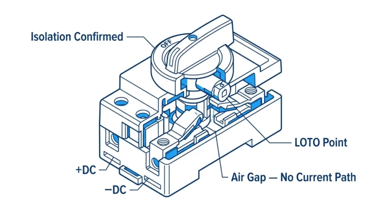
Antes de comenzar cualquier trabajo de cableado del SPD, verifique la desenergización completa del sistema utilizando los procedimientos adecuados de bloqueo/etiquetado (LOTO). Abra todas las desconexiones de CC entre las matrices FV y los inversores, eliminando todas las fuentes de energía posibles. Incluso con las desconexiones abiertas, las matrices generan tensión cada vez que la luz incide sobre los módulos, lo que supone un riesgo de descarga.
Utilice un multímetro calibrado para verificar la tensión cero entre todos los pares de conductores donde se instalará el SPD. Pruebe positivo a negativo, positivo a tierra y negativo a tierra para confirmar la desenergización completa. Es posible que los conjuntos sigan generando tensión, pero no debería aparecer en el lugar de la instalación con los seccionadores aguas arriba correctamente abiertos.
Cubra los módulos de la matriz con lonas opacas o instálelos durante las horas nocturnas si se requieren condiciones de tensión cero absoluta. La mayoría de los fabricantes exigen una instalación sin tensión, pero algunos diseños de SPD permiten la instalación con tensión por parte de personal cualificado.
Posicione la ubicación de montaje del SPD dentro del armario minimizando las distancias a los puntos de conexión en barras colectoras o bloques de terminales. La mayoría de los SPD se montan en un carril DIN estándar de 35 mm, lo que facilita su colocación y extracción. Asegúrese de que la ubicación de montaje permite el acceso a los terminales para las conexiones de los conductores y la visibilidad del indicador de estado sin necesidad de retirar la cubierta del armario.
La mayoría de los fabricantes especifican una separación mínima con los equipos adyacentes. Los SPD generan calor durante el funcionamiento normal y mucho más durante las sobretensiones, lo que requiere un flujo de aire para la refrigeración. Una separación inadecuada provoca el fallo prematuro del SPD o la degradación de su rendimiento.
Fije firmemente el SPD al raíl o superficie de montaje utilizando los herrajes suministrados. Un montaje flojo puede provocar daños por vibraciones y conexiones eléctricas deficientes. Verifique la seguridad del montaje intentando mover el SPD: los dispositivos montados correctamente no deben moverse bajo una presión moderada de la mano.
NEC 690.35(C) requiere medios de desconexión para los SPD con una tensión nominal superior a la tensión máxima de funcionamiento continuo (MCOV) del dispositivo de protección contra sobretensiones. Esta desconexión permite la sustitución segura del SPD sin desenergizar todo el sistema. Algunos modelos de SPD incluyen desconexiones integrales (a menudo portafusibles montados en carril DIN) que eliminan los requisitos de desconexión por separado.
Cuando se requiera un seccionador separado, instale el seccionador inmediatamente adyacente al SPD minimizando la longitud del conductor sin protección entre el seccionador y el SPD. Utilice un seccionador apto para tensión CC y corriente continua según los requisitos del sistema. Etiquete el seccionador identificando claramente su función y relación con el SPD.
Los desconectadores con fusibles proporcionan tanto la función de desconexión como la protección contra sobrecorriente para el SPD y los conductores asociados. Seleccione los valores nominales de los fusibles según las recomendaciones del fabricante del SPD, normalmente de 10 A a 32 A dependiendo del modelo de SPD y de la exposición a sobretensiones prevista. Nunca utilice disyuntores como desconectadores de SPD a menos que el fabricante lo apruebe específicamente para esta aplicación.
Empiece las conexiones de los conductores en los terminales de línea del SPD (positivo y negativo). Pele el aislamiento del conductor a la longitud especificada por el fabricante del terminal, normalmente 10-12 mm para terminales de tornillo, 8-10 mm para terminales de resorte. Evite que el conductor quede excesivamente expuesto, ya que podría provocar descargas eléctricas o contactos involuntarios con superficies conectadas a tierra.
Inserte completamente el conductor pelado en el terminal, asegurándose de que no quede ningún conductor desnudo fuera del cuerpo del terminal. Apriete los terminales de tornillo al par especificado por el fabricante del SPD, normalmente de 0,9 a 1,4 N⋅m (8 a 12 lb-in) para terminales M4, mayor para terminales más grandes. Utilice un dinamómetro calibrado para evitar tanto el apriete insuficiente (contacto deficiente) como el apriete excesivo (daños en el conductor).
Para terminales con resorte, inserte el conductor hasta que llegue al tope del terminal y luego verifique la conexión tirando del conductor con una fuerza moderada. Las conexiones correctamente asentadas resisten fuerzas de extracción superiores a 50 N (11 lbf). Si el conductor se suelta, inspeccione el terminal y el conductor en busca de daños, corrija cualquier problema y vuelva a instalarlo.
Consejo profesional: Tome fotos de todas las conexiones de los conductores antes de cerrar los armarios: estas fotos de referencia resultan muy valiosas durante la resolución de problemas y las inspecciones. Las fotos también documentan los procedimientos de instalación adecuados para que otros técnicos que no estén familiarizados con la instalación puedan consultarlas en el futuro.
La conexión del conductor de puesta a tierra del equipo (EGC) al terminal de tierra del SPD representa la conexión más crítica que afecta al rendimiento de la protección contra sobretensiones. Dirija el EGC desde el terminal de tierra del SPD hasta la barra colectora de puesta a tierra del armario o la conexión del electrodo de puesta a tierra utilizando el camino más corto posible. Evite bucles, bobinas o curvas innecesarias que aumenten la inductancia del conductor y degraden la eficacia del SPD.
Pele el aislamiento del EGC según los requisitos del terminal e insértelo completamente en el terminal de tierra del SPD. Apriete con el par de apriete especificado para garantizar un contacto eléctrico excelente. Las conexiones a tierra deficientes provocan un aumento de tensión en los terminales del SPD durante eventos de sobretensión, lo que puede dañar los equipos protegidos a pesar de la presencia del SPD.
Si el terminal de tierra del SPD y el bus de tierra de la caja no están a una distancia de línea directa, utilice curvas de radio grande (radio mínimo de 150 mm/6″) en lugar de curvas cerradas de 90 grados. La corriente de sobretensión que fluye a través de las curvas cerradas crea campos magnéticos localizados que inducen tensiones opuestas al flujo de corriente, aumentando efectivamente la impedancia del conductor.
Completar el cableado del SPD terminando los conductores de línea en las barras colectoras del sistema o en los bloques de terminales. El conductor positivo va a la barra positiva y el negativo a la barra negativa, manteniendo la polaridad correcta. Utilice terminales o posiciones de terminales independientes para los conductores del SPD en lugar de duplicar los conductores en terminales que ya contengan conductores de circuito.
Siga los mismos procedimientos de pelado, inserción y par de apriete utilizados para las conexiones de terminales SPD. Compruebe que los valores nominales de los terminales superan la corriente prevista, incluidas las contribuciones de corriente continua y de sobretensión. Algunas jurisdicciones exigen terminales específicos para las conexiones de los SPD para facilitar la sustitución futura de los SPD sin alterar las conexiones de otros circuitos.
Etiquete todos los conductores del SPD en ambos extremos con una identificación permanente que indique “Conexión SPD” y haga referencia a la unidad SPD específica si existen varios SPD en el armario. El etiquetado facilita el mantenimiento futuro y evita la desconexión accidental durante trabajos no relacionados.

La eficacia de los SPD depende en gran medida de una conexión a tierra adecuada que conecte la corriente de sobretensión a tierra con una impedancia mínima. Comprender la distinción entre el conductor de puesta a tierra del equipo (EGC) y el conductor del electrodo de puesta a tierra (GEC) garantiza que las conexiones a tierra del SPD cumplan tanto los requisitos del código como los criterios de rendimiento óptimo.
El conductor de puesta a tierra del equipo (EGC) según el artículo 250 de NEC proporciona una vía de retorno de la corriente de fallo de tierra desde el equipo hasta el conductor de puesta a tierra del sistema o neutro. Para aplicaciones SPD, el EGC conecta el terminal de tierra del SPD a la barra colectora de puesta a tierra del armario, creando un enlace eléctrico entre el SPD y el chasis del equipo. El dimensionamiento del EGC sigue la tabla 250.122 de NEC en función de la capacidad de protección contra sobrecorriente del circuito.
El conductor del electrodo de puesta a tierra (GEC) conecta la barra colectora de puesta a tierra al sistema de electrodos de puesta a tierra (varillas de tierra, electrodos revestidos de hormigón, acero del edificio, etc.) proporcionando una verdadera conexión a tierra. El GEC representa la vía final para que la corriente de sobretensión desviada por los SPD se disipe en la tierra. El dimensionamiento del GEC sigue la tabla 250.66 de NEC en función del tamaño del conductor de servicio, normalmente mayor que el EGC.
El concepto crítico: Los SPD deben conectarse tanto al EGC (para la unión con el equipo) como, en última instancia, a través del GEC a la toma de tierra (para la disipación de la corriente de sobretensión). Muchas instalaciones conectan incorrectamente los SPD sólo al chasis del equipo sin verificar la conexión al sistema de electrodos de puesta a tierra, lo que reduce significativamente la eficacia del SPD.
La inductancia del conductor de tierra representa el principal factor que limita el rendimiento de la desviación de sobretensiones del SPD. Cada conductor presenta una inductancia (normalmente 300-500nH por metro para un cable típico de edificio) que se opone a los cambios rápidos de corriente. Durante los eventos de sobretensión de subida rápida (tiempos de subida de submicrosegundos), incluso los cables de tierra cortos desarrollan una caída de tensión significativa a través de la inductancia del cable que puede superar los valores nominales de tensión del equipo protegido.
Calcule la caída de tensión aproximada a través de la inductancia del cable de tierra utilizando V = L(di/dt) donde L es la inductancia del cable y di/dt es la velocidad de cambio de la corriente de sobretensión. Para un cable de tierra de 1 metro (400nH) que conduce una sobretensión de 10kA con un tiempo de subida de 1μs: V = 400nH × (10.000A/1μs) = 4.000V. Esta tensión de 4 kV se añade a la tensión de bloqueo del SPD, lo que puede dañar el equipo a pesar de la presencia del SPD.
Minimice la inductancia del cable de tierra mediante múltiples técnicas de eficacia probada:
La longitud más corta posible: Cada centímetro ahorrado reduce proporcionalmente la inductancia. Dirija los conductores de tierra directamente a la barra colectora de tierra sin rodeos innecesarios.
Mayor tamaño práctico del conductor: Los conductores más grandes presentan menor inductancia por unidad de longitud. El uso de 6 AWG en lugar de 14 AWG reduce la inductancia aproximadamente 30%.
Evitar bucles y espirales: Cualquier bucle en el conductor crea un campo magnético que aumenta drásticamente la inductancia. Mantenga los conductores de tierra rectos con curvas de gran radio sólo cuando sea necesario.
Caminos de tierra paralelos: Varios conductores de tierra en paralelo reducen la inductancia combinada. Siempre que sea posible, utilice dos conductores de tierra en lugar de uno para las conexiones SPD críticas.
| Longitud del cable de tierra | Inductancia aproximada | Caída de tensión @ 10kA/μs | Calificación del rendimiento |
|---|---|---|---|
| 150 mm (6″) | 60nH | 600V | Excelente |
| 300 mm (12″) | 120nH | 1,200V | Bien |
| 500 mm (20″) | 200nH | 2,000V | Aceptable |
| 1000mm (40″) | 400nH | 4,000V | Pobre-Requerimiento Requerido |
⚠️ Importante: Muchos inspectores eléctricos miden la longitud del cable de tierra durante las inspecciones. Los cables que superan los 300 mm (12 pulgadas) suelen dar lugar a avisos de corrección que exigen una revisión. Antes de comenzar la instalación, planifique las ubicaciones de montaje de los SPD de modo que las longitudes de los cables de tierra cumplan con el código.
Los sistemas con varias instalaciones de SPD requieren una atención especial a la conexión a tierra para evitar que circulen corrientes de tierra y garantizar que todos los SPD compartan una referencia de tierra común. Cada SPD debe conectarse a la barra colectora de tierra del equipo local que, a su vez, se conecta al sistema de electrodos de tierra del edificio a través de una única conexión GEC por zona del edificio.
Evite crear múltiples caminos de tierra paralelos entre diferentes secciones del sistema que creen bucles de tierra que permitan la circulación de corrientes parásitas durante el funcionamiento normal. Los bucles de tierra también crean tensiones diferenciales entre puntos de tierra supuestamente equipotenciales que pueden provocar la activación de SPD molestos o una desviación inadecuada de las sobretensiones.
En grandes instalaciones fotovoltaicas que abarquen varias zonas de tejados o edificios, establezca una conexión a tierra de punto único en la entrada de servicio principal o en el punto de conexión a tierra designado. Todas las barras colectoras de tierra del equipo en cajas combinadoras, inversores y otros recintos se conectan entre sí y, en última instancia, a este único punto de conexión a tierra, lo que evita múltiples conexiones a tierra que crean bucles de tierra.
Artículo 690 de NEC.35 especifica los requisitos obligatorios de los dispositivos de protección contra sobretensiones para los sistemas fotovoltaicos situados en lugares expuestos a rayos. Aunque la norma 690.35 no obliga a instalar SPD en todas las instalaciones, las mejores prácticas recomiendan la protección con SPD independientemente de los requisitos del código, dada la alta vulnerabilidad a los rayos de los sistemas fotovoltaicos elevados y el costoso potencial de daños en los equipos.
La sección 690.35(A) requiere “un dispositivo de protección contra sobretensiones listado” observando el uso de la palabra “un” en lugar del plural “dispositivos”. Sin embargo, una protección eficaz suele requerir varios SPD en diferentes ubicaciones del sistema para crear una protección de defensa en profundidad. Las instalaciones de un solo SPD rara vez proporcionan una protección adecuada, excepto en los sistemas residenciales más pequeños con recorridos mínimos de conductores.
Los SPD deben estar “listados” según 690.35(A), lo que requiere la certificación de terceros por parte de un laboratorio de pruebas reconocido a nivel nacional (NRTL), como UL, ETL o CSA. Los dispositivos homologados llevan una marca de certificación en la placa de características o documentación que demuestre el cumplimiento de las normas aplicables. El uso de SPD no incluidos en la lista infringe el código y los requisitos del seguro.
La sección 690.35(B) especifica las ubicaciones de conexión del SPD: “en la fuente de CC o en los circuitos de salida de CC”. Este lenguaje permite la flexibilidad de instalar los SPD en la ubicación del conjunto (fuente de CC), en las entradas del inversor (circuitos de salida de CC) o en ambas ubicaciones para mejorar la protección. La instalación en ambas ubicaciones proporciona una protección óptima, pero a un coste mayor.
La sección requiere además que los SPD estén “conectados a los conductores del circuito desde los conductores sin conexión a tierra hasta la tierra”. Este enunciado exige que los SPD se conecten entre los conductores de CC sin conexión a tierra (positivos y negativos) y la tierra del equipo, no sólo entre los conductores positivos y negativos. Una conexión adecuada requiere tres SPD terminales o dos SPD separados que cubran las trayectorias positivo-tierra y negativo-tierra.
El apartado 690.35(C) exige medios de desconexión para los SPD a menos que estén integrados en el conjunto del SPD. Los medios de desconexión deben ser fácilmente accesibles para permitir la sustitución del SPD sin desenergizar todo el sistema FV. Este requisito reconoce que los SPD son elementos de mantenimiento sujetos a sustitución periódica tras la exposición a sobretensiones o el envejecimiento. Las instalaciones que incumplan este requisito obligarán a desconectar todo el sistema para proceder a la sustitución rutinaria de los SPD.
Aunque 690.35 no especifica el tamaño mínimo del conductor, las normas generales de cableado de los artículos 310 y 250 de NEC establecen los requisitos de tamaño. La mayoría de los diseñadores especifican un mínimo de 10 AWG para las conexiones de los SPD, lo que proporciona una capacidad de corriente y una resistencia mecánica adecuadas a la vez que satisface las expectativas de los inspectores.
La sección 690.35(D) aborda la protección contra sobrecorriente para conductores de SPD que requieren protección contra sobrecorriente según el Artículo 240, a menos que los conductores cumplan las reglas de derivación u otras excepciones. Muchos diseñadores instalan fusibles o disyuntores para proteger los circuitos derivados de los SPD contra condiciones de sobrecorriente. Los valores nominales de los fusibles suelen ser de 10 A a 32 A, dependiendo de la intensidad nominal continua del SPD y de la exposición prevista a sobretensiones.
Algunos modelos de SPD incluyen protección de sobreintensidad integrada, lo que elimina la necesidad de un dispositivo de protección independiente. La protección integrada simplifica la instalación y reduce el número de piezas, pero requiere la sustitución completa del SPD si el dispositivo de sobreintensidad funciona, en lugar de la simple sustitución del fusible.

Problema: La instalación de SPD con conductores de tierra de más de 300 mm (12 pulgadas) reduce drásticamente la eficacia de la protección contra sobretensiones. Los conductores de tierra largos presentan una inductancia elevada que crea una caída de tensión durante los eventos de sobretensión que se suma a la tensión de apriete del SPD, lo que puede provocar daños en el equipo. Esto representa el defecto de instalación de SPD más común encontrado durante las inspecciones eléctricas.
Escenarios comunes:
- Montaje de los SPD lejos de la barra colectora de puesta a tierra de la caja que requiere un tendido ampliado del conductor de tierra
- Enrutamiento de los conductores de tierra a través de canales de cables o bandejas de cables que añaden longitud innecesaria.
- Utilización de cables multiconductores agrupados para conexiones de SPD en las que el conductor de tierra tiene un exceso de holgura.
Corrección: Reubique la posición de montaje del SPD minimizando la distancia a la barra colectora de puesta a tierra o redirija el conductor de tierra utilizando la ruta más directa posible. Muchas instalaciones requieren modificaciones de la caja (taladrado de orificios de montaje, reubicación del carril DIN) para conseguir la longitud adecuada del conductor de tierra. Considere la posibilidad de añadir una barra colectora de tierra auxiliar cerca del SPD si la ubicación de la barra colectora de tierra existente impide una instalación conforme al código.
Problema: Las conexiones sueltas de los conductores en los terminales de los SPD o en las barras colectoras crean puntos de contacto de alta resistencia que se calientan excesivamente durante las sobretensiones y el funcionamiento continuo. El par de apriete inadecuado suele producirse cuando los instaladores utilizan herramientas no calibradas o adivinan el nivel de apriete adecuado. Las conexiones flojas fallan en la inspección eléctrica y suponen un riesgo de incendio durante el funcionamiento.
Escenarios comunes:
- Uso de llaves ajustables o alicates en lugar de torquímetros calibrados
- Apriete excesivo de un terminal e insuficiente de otros debido a una aplicación de fuerza incoherente.
- No verificar el par de apriete de los terminales tras la instalación inicial durante la inspección final de calidad.
Corrección: Utilice siempre un destornillador o llave dinamométrica debidamente calibrados y ajustados al valor de par de apriete especificado por el fabricante del SPD. Las especificaciones típicas de par de apriete de los terminales oscilan entre 0,9 y 1,4 N⋅m (8 y 12 lb-in) para terminales M4 estándar. Anote los valores de par alcanzados en la lista de comprobación de la instalación y verifique todas las conexiones antes de cerrar la caja.
⚠️ Importante: Algunos modelos de SPD utilizan terminales con resorte que sólo requieren fuerza de inserción sin ajuste de par de apriete. Verifique el método de instalación con las instrucciones del fabricante: intentar apretar los terminales de resorte daña el mecanismo del terminal y crea conexiones deficientes.
Problema: NEC 690.35(C) exige medios de desconexión accesibles para los SPD que permitan una sustitución segura. Las instalaciones que omiten las desconexiones o utilizan ubicaciones de desconexión inaccesibles infringen el código y crean riesgos de seguridad durante la sustitución del SPD, lo que obliga a los técnicos a trabajar sobre conductores energizados. Los desconectadores que faltan no pasan la inspección eléctrica y requieren costosas reparaciones.
Escenarios comunes:
- Suponiendo que las tapas integrales de los terminales SPD cumplan el requisito de desconexión (no es así)
- Instalación de la desconexión en el interior de la caja del inversor accesible sólo para los técnicos de servicio del inversor.
- Utilizar disyuntores como desconectadores sin verificar la aprobación del fabricante para esta aplicación.
Corrección: Instale un desconectador con fusible fácilmente accesible inmediatamente adyacente al SPD cuando no esté integrado en el conjunto del SPD. Utilice un desconectador adecuado para la tensión continua del sistema con un fusible de acuerdo con las recomendaciones del fabricante del SPD. Etiquete el desconectador claramente con la advertencia “Desconectador del SPD - No retirar bajo carga”.
Problema: Conectar el terminal positivo del SPD a la barra colectora negativa y el terminal negativo a la barra colectora positiva crea una protección incorrecta o daños potenciales en los SPD que utilizan elementos de protección sensibles a la polaridad. Aunque muchos diseños de SPD toleran la polaridad inversa sin fallo inmediato, el rendimiento de la protección se degrada significativamente. Algunos tipos de SPD (especialmente los que utilizan elementos semiconductores) fallan inmediatamente cuando se conectan en sentido inverso.
Escenarios comunes:
- Lectura errónea de las etiquetas de los conductores en cajas abarrotadas con múltiples colores de cables.
- Suponiendo que los dos terminales de línea del SPD son idénticos sin comprobar las marcas de polaridad
- Utilización de barras colectoras no marcadas en cajas de combinadores sin verificar cuáles son positivas y cuáles negativas.
Corrección: Verifique la polaridad del conductor tanto en el extremo del SPD como en el extremo de la barra colectora antes de realizar las conexiones finales. Utilice un multímetro para confirmar que los conductores positivos muestran el voltaje esperado en relación con los negativos cuando el sistema está energizado. Siga un código de colores coherente (rojo positivo, negro negativo) en toda la instalación. Etiquete claramente todos los terminales del SPD y las barras colectoras con marcas de polaridad visibles durante el mantenimiento.
Antes de energizar circuitos SPD recién instalados, realice una inspección exhaustiva verificando todos los requisitos de instalación. La inspección visual detecta los errores más comunes y evita daños en los equipos o infracciones de la normativa durante la primera puesta en servicio. Una lista de comprobación sistemática evita que se pasen por alto detalles críticos durante la puesta en marcha apresurada del sistema.
Verifique que el modelo de SPD instalado sea el correcto y que coincida con la tensión nominal de CC del sistema y las especificaciones de corriente de sobretensión. Confirme que la tensión nominal del SPD es igual o superior a la tensión de funcionamiento de CC máxima del sistema con el margen de seguridad adecuado. Compruebe que el valor nominal de la corriente de sobretensión del SPD (Iimp para el Tipo 1, In para el Tipo 2) cumple los requisitos del sistema según la evaluación de amenazas y las recomendaciones del fabricante.
Inspeccione todas las conexiones de conductores en los terminales del SPD y en las barras colectoras del sistema, verificando la profundidad de inserción adecuada, la aplicación del par de apriete y la ausencia de conductores expuestos fuera de los terminales. Asegúrese de que los conductores no muestren signos de daños en el aislamiento, muescas o marcas de compresión que indiquen una manipulación inadecuada. Verifique que las marcas o etiquetas de los cables identifiquen la función y el destino del conductor.
Mida la longitud del conductor de tierra desde el terminal de tierra del SPD hasta la barra colectora de tierra confirmando una longitud máxima ≤300mm (12 pulgadas). Compruebe que el conductor de tierra sigue la ruta más directa sin bucles, bobinas o curvas cerradas innecesarias. Compruebe que el tamaño del conductor de tierra cumple el requisito mínimo de 10 AWG (si es mayor, mejor).
Utilizando un multímetro ajustado en el modo de resistencia (Ω) con los cables de prueba del SPD desconectados, mida la resistencia entre cada terminal de línea del SPD y el terminal de tierra. Las lecturas deben mostrar una resistencia alta (megaohmios), lo que indica que el SPD está en estado de espera (no conductor). Las lecturas de baja resistencia (menos de 1kΩ) sugieren daños en el SPD que requieren su sustitución antes de la energización.
Mida la resistencia entre los terminales de línea del SPD y la barra colectora de puesta a tierra verificando que el conductor de tierra proporciona una ruta de baja resistencia a tierra. Las lecturas típicas deben mostrar menos de 0,5Ω para conductores de tierra 10 AWG correctamente instalados de menos de 300 mm de longitud. Una resistencia mayor indica conexiones deficientes que requieren corrección.
Pruebe la continuidad de la ruta del conductor de puesta a tierra del equipo desde el terminal de tierra del SPD a través de la barra colectora de puesta a tierra del recinto hasta el conductor del electrodo de puesta a tierra. Esta prueba de continuidad de extremo a extremo verifica la trayectoria completa de la conexión a tierra sin aperturas ni conexiones de alta resistencia. Las lecturas superiores a 1Ω sugieren problemas en el sistema de puesta a tierra que requieren investigación y corrección.
Una vez finalizada la inspección visual y las pruebas eléctricas, conecte el sistema siguiendo los procedimientos del fabricante. La mayoría de los SPD disponen de indicadores visuales de estado (normalmente un LED verde o un indicador mecánico) que confirman su correcto funcionamiento. Verifique que el indicador de estado muestre un estado “saludable” u “operativo” inmediatamente después de la energización.
Mida la tensión en los terminales del SPD con un multímetro ajustado en el modo de tensión continua para la tensión del sistema. La lectura de la tensión debe ser igual a la tensión de funcionamiento del sistema, lo que confirma que el SPD en la conexión en paralelo ve la tensión del circuito completo. Una tensión significativamente inferior a la esperada sugiere un error de conexión en serie o un fallo del conductor paralelo.
Supervise los indicadores de estado del SPD durante las primeras 24 horas de funcionamiento y observe cualquier cambio que sugiera la activación o el fallo del SPD. Muchos SPD incluyen contactos de alarma que permiten la supervisión remota del estado del SPD a través de los sistemas de gestión de edificios. Conecte los contactos de alarma al sistema de monitorización según los diagramas de cableado del fabricante para permitir alertas automáticas de fallos del SPD.
Establezca un programa de inspección periódica de los SPD comprobando los indicadores de estado y la condición física trimestralmente como mínimo. La inspección visual detecta los fallos de los SPD antes de que comprometan la protección del sistema, lo que permite sustituirlos a tiempo. Programe las inspecciones durante otras visitas de mantenimiento rutinarias para minimizar los costes de acceso al emplazamiento.
Inspeccione los indicadores de estado del SPD verificando el estado verde “sano” en todos los dispositivos. Los indicadores de estado defectuosos (rojo, amarillo u oscuro) requieren la sustitución inmediata del SPD. Documentar el estado de todos los SPD en el registro de mantenimiento con la fecha de inspección y el nombre del inspector para crear un registro histórico del estado del SPD.
Examine la carcasa y los terminales del SPD en busca de signos de sobrecalentamiento (decoloración, fusión, olor a quemado) que indiquen un flujo de corriente excesivo o conexiones deficientes. Compruebe el aislamiento del conductor cerca de los terminales para ver si hay daños por calor o fragilidad que sugieran estrés térmico. Cualquier signo de sobrecalentamiento requiere una investigación y corrección inmediatas.
Sustituya los SPD inmediatamente cuando los indicadores de estado muestren una condición de fallo, independientemente del tiempo transcurrido desde su instalación. Los SPD averiados ya no proporcionan protección contra sobretensiones, lo que deja el equipo vulnerable a daños. Muchos fallos de los SPD se producen después de eventos de sobretensión importantes: inspeccione todos los SPD después de tormentas eléctricas que pasen a menos de 5 km de la instalación.
Sustituya los SPD que alcancen la vida útil especificada por el fabricante incluso cuando los indicadores de estado muestren un estado saludable. La vida útil típica de los SPD oscila entre 3 y 10 años, dependiendo de la exposición a sobretensiones y de las condiciones ambientales. Documente las fechas de instalación para permitir una sustitución proactiva antes de que se produzcan fallos al final de la vida útil.
Considere la posibilidad de sustituir los SPD cuando los indicadores de estado muestren con frecuencia activaciones (indicadores amarillos o intermitentes temporales) que sugieran que el SPD se está acercando a los límites de su capacidad. Las activaciones frecuentes indican una elevada actividad de rayos local que supera la evaluación de amenaza original. La actualización a tipos de SPD de mayor capacidad (Tipo 1 en lugar de Tipo 2, valores nominales de corriente de sobretensión más altos) proporciona una mejor protección en estas situaciones.
Tras la sustitución del SPD, repita los procedimientos de puesta en servicio verificando la correcta instalación del dispositivo de sustitución. Compruebe los indicadores de estado, mida las tensiones y verifique el funcionamiento de los contactos de alarma. Documente la fecha de sustitución, el nuevo modelo y número de serie del SPD y cualquier cambio en la configuración de protección del sistema.
Investigue la causa del fallo del SPD para identificar posibles problemas del sistema. Los SPD que fallan poco después de la instalación sugieren errores de cableado, conexión a tierra inadecuada o selección de SPD de baja tensión. El fallo simultáneo de varios SPD indica un evento de sobretensión grave o un fallo del sistema de tierra. Aborde las causas principales para evitar fallos repetitivos.
NEC 690.35 especifica un mínimo de conductores de cobre 14 AWG para las conexiones de los SPD, pero la mayoría de las instalaciones profesionales utilizan 10 AWG, lo que proporciona un mejor manejo de la corriente de sobretensión y una menor inductancia. El tamaño del conductor afecta directamente al rendimiento del SPD: los conductores más grandes (6 AWG o 4 AWG) reducen aún más la inductancia y mejoran la eficacia de la protección, especialmente en instalaciones de alto riesgo.
El tamaño de los conductores de tierra debe ser igual o superior al de los conductores de línea, siendo 10 AWG el mínimo práctico. Algunos diseñadores especifican conductores de tierra de un tamaño mayor que los conductores de línea, reconociendo la importancia crítica de una trayectoria de tierra de baja inductancia. La longitud del conductor es más importante que el tamaño; incluso los conductores grandes pierden eficacia cuando son excesivamente largos.
Calcule el tamaño del conductor teniendo en cuenta tanto la corriente continua nominal como la capacidad de sobrecorriente. Los conductores de línea SPD ven una corriente continua mínima (corriente de fuga típicamente <1mA) pero deben soportar corrientes de sobretensión que pueden superar los 100kA brevemente. Mientras que los conductores sobreviven a estas corrientes extremas debido a su breve duración, los tamaños más grandes proporcionan una mejor distribución de la corriente de sobretensión reduciendo el calentamiento localizado.
Las mejores prácticas del sector recomiendan que la longitud combinada de la línea y el cable de tierra no supere los 500 mm (20 pulgadas) y que el cable de tierra no supere los 300 mm (12 pulgadas). Los cables más cortos siempre ofrecen un mejor rendimiento: las instalaciones con cables de tierra de 150 mm (6 pulgadas) ofrecen una protección óptima. La caída de tensión a través de la inductancia del cable de tierra se añade directamente a la tensión de bloqueo del SPD, lo que puede dañar el equipo si los cables tienen una longitud excesiva.
Cada 100 mm (4 pulgadas) de longitud de cable añade aproximadamente 40 nH de inductancia. Durante una sobretensión de 10 kA con un tiempo de subida de 1μs, esto crea una caída de tensión de 400 V por cada 100 mm de longitud de cable. Para un equipo de 1000 V con un nivel de aislamiento de 1400 V, mantener la tensión añadida por debajo de 400 V requiere cables de tierra de menos de 100 mm, un objetivo difícil pero alcanzable con una planificación cuidadosa.
Cuando las limitaciones físicas impidan alcanzar la longitud óptima del cable de tierra, utilice el tamaño de conductor más grande posible y evite bucles o bobinas en el trazado del conductor. Considere la posibilidad de añadir barras colectoras de tierra suplementarias más cerca de las ubicaciones de los SPD o de reubicar los SPD en posiciones que permitan conexiones de tierra más cortas. Invertir tiempo en optimizar la longitud del cable de tierra durante la instalación proporciona beneficios de protección que duran toda la vida útil del sistema.
La mayoría de los fabricantes de SPD prohíben la instalación en sistemas energizados y exigen la desenergización completa antes de empezar a trabajar. Los sistemas solares fotovoltaicos presentan desafíos únicos, ya que los paneles generan tensión siempre que están iluminados, lo que dificulta la desenergización real. Para una instalación más segura, cubra los paneles con lonas opacas o programe la instalación durante las horas nocturnas para conseguir condiciones de tensión cero.
Algunos diseños especializados de SPD permiten la instalación “en caliente” por parte de electricistas cualificados que utilicen equipos de protección individual (EPI) adecuados. Estas instalaciones requieren ropa clasificada para arco eléctrico, herramientas aisladas y procedimientos de trabajo seguros detallados. Nunca intente instalar un SPD energizado sin la aprobación explícita del fabricante, la formación adecuada y un EPI completo para arco eléctrico clasificado para la corriente y tensión de fallo del sistema.
Cuando las matrices deban permanecer descubiertas durante la instalación, abra todos los seccionadores de CC aguas arriba que aíslen la zona de trabajo de la tensión de la matriz. Verifique que no haya tensión en el lugar de trabajo utilizando un multímetro de la capacidad adecuada antes de comenzar las conexiones de los conductores. Incluso con aislamiento, manténgase alerta al arco eléctrico durante toda la instalación, ya que la tensión del conjunto puede aparecer en el lugar de trabajo a través de fallos a tierra inesperados o fallos del dispositivo de aislamiento.
El comportamiento de los SPD con polaridad invertida depende de los tipos de elementos de protección internos utilizados. Los SPD basados en MOV (el tipo más común) son dispositivos no polarizados que toleran la conexión inversa sin daños inmediatos: los MOV conducen bidireccionalmente independientemente de la polaridad. Sin embargo, incluso los SPD basados en MOV pueden incluir otros componentes (circuitos indicadores, contactos de alarma) que son sensibles a la polaridad y funcionan mal cuando se invierten.
Los SPD basados en semiconductores que utilizan diodos de avalancha de silicio son muy sensibles a la polaridad y fallan inmediatamente cuando se conectan en sentido inverso. Estos dispositivos conducen la corriente de sobretensión en una sola dirección: la conexión inversa permite que aparezca toda la tensión de sobretensión en el equipo protegido sin que se active el SPD. Algunos diseños de SPD de semiconductor incluyen protección contra polaridad inversa, pero la mayoría no lo hacen, por lo que la polaridad correcta es crítica.
Los SPD híbridos que combinan múltiples tecnologías de protección (GDT + MOV + diodo) muestran una tolerancia a la polaridad inversa mixta en función de la arquitectura. Compruebe siempre la polaridad correcta antes de conectar los SPD recién instalados. Los fabricantes marcan la polaridad en la carcasa del SPD utilizando símbolos + y -, códigos de colores o etiquetas de terminales. Siga exactamente estas marcas durante la instalación para evitar fallos de protección o daños en el SPD.
La estrategia óptima de colocación del SPD depende del tamaño de la instalación, la exposición del conjunto y la evaluación de la amenaza. Los sistemas residenciales pequeños (de 2 a 4 cadenas) suelen utilizar un único SPD a la salida del combinador para proteger todo el conjunto con una eficacia adecuada y un coste mínimo. Los sistemas comerciales más grandes (más de 6 cadenas) se benefician de los SPD a nivel de cadena que proporcionan protección independiente para cada cadena más un SPD adicional a la salida del combinador, creando una protección en dos fases.
Los SPD a nivel de ramal proporcionan una protección superior al interceptar las sobretensiones inmediatamente en el punto de entrada en el sistema eléctrico antes de que la energía se acople a otros ramales. Esta protección independiente de los strings impide que un solo rayo dañe otros strings o equipos aguas abajo. El coste adicional de varios SPD se justifica en instalaciones de alta exposición o en sistemas que protegen inversores caros.
Las instalaciones repartidas por varias secciones de tejado o edificios requieren sin duda SPD en cada ubicación. Los largos tramos de conductores de CC entre matrices separadas actúan como antenas que recogen la energía de sobretensión inducida incluso sin impactos directos. La protección SPD local en cada ubicación de la matriz intercepta esta energía antes de que se propague a través del cableado entre edificios, dañando potencialmente los equipos en ubicaciones distantes.
Las especificaciones de par de apriete de los terminales de los SPD varían según el fabricante y el tamaño del terminal, pero los valores típicos oscilan entre 0,9 y 1,4 N⋅m (8 y 12 lb-in) para los terminales de tornillo M4 estándar utilizados en la mayoría de los SPD de tamaño medio. Los SPD más grandes con terminales M5 o M6 pueden especificar 1,5 a 2,5 N⋅m (13 a 22 lb-in). Compruebe siempre las especificaciones del fabricante en las instrucciones de instalación, ya que los valores genéricos pueden provocar un apriete insuficiente (contacto deficiente) o excesivo (daños en el conductor o el terminal).
Utilice un destornillador dinamométrico calibrado o una llave ajustada al valor especificado en lugar de adivinar el apriete por tacto. La percepción humana del par de apriete varía mucho: los estudios demuestran que los técnicos que utilizan el “tacto” alcanzan un par de apriete real que oscila entre 40% y 200% del valor objetivo. Esta inconsistencia crea conexiones poco fiables que afectan tanto a la seguridad como al rendimiento. Las herramientas calibradas cuestan menos de $100, pero eliminan esta variabilidad y ofrecen resultados uniformes.
Algunos diseños de SPD utilizan terminales a presión con resorte que eliminan los requisitos de par de apriete: basta con insertar el conductor pelado hasta que haga clic o alcance el tope físico. Estos terminales aplican automáticamente la fuerza de contacto correcta. Verifique la correcta inserción tirando del conductor con una fuerza moderada; los conductores correctamente asentados resisten la extracción. No intente nunca apretar los terminales de resorte con herramientas, ya que se dañaría el mecanismo del terminal.
La mayoría de los SPD modernos incluyen indicadores visuales de estado (luces LED o banderas mecánicas) que muestran el estado del dispositivo. El indicador verde suele indicar un funcionamiento correcto, mientras que el indicador rojo u oscuro indica un fallo que requiere una sustitución inmediata. Inspeccione los indicadores de estado trimestralmente durante el mantenimiento rutinario y observe cualquier cambio en el estado que sugiera que el SPD se acerca al final de su vida útil.
Algunos SPD fallan repentinamente después de sobretensiones importantes, mientras que otros se degradan gradualmente a lo largo de los años. Los fallos repentinos suelen producirse cuando las sobretensiones superan la capacidad nominal del SPD y destruyen los elementos internos de protección. Los fallos graduales se deben a la exposición acumulativa a numerosas sobretensiones más pequeñas que acaban agotando la capacidad del SPD. Ambos modos de fallo activan indicadores de estado cuando funcionan correctamente.
Muchos SPD comerciales incluyen contactos de alarma remotos que permiten la integración de la supervisión automatizada con los sistemas de gestión de edificios. Conecte estos contactos de alarma según los diagramas de cableado del fabricante para permitir notificaciones automáticas cuando se produzcan fallos en el SPD. La supervisión remota resulta especialmente valiosa en lugares remotos en los que las inspecciones manuales trimestrales son poco prácticas, ya que permite la notificación inmediata de fallos y la programación inmediata de sustituciones.
El cableado correcto de los SPD de CC representa un factor crítico que determina la eficacia de la protección en los sistemas solares fotovoltaicos. Si se siguen los procedimientos detallados, los métodos de conexión a tierra y los diagramas de cableado que se presentan en esta guía, se garantiza que las instalaciones cumplan los requisitos de la norma NEC 690.35 y, al mismo tiempo, ofrezcan el máximo rendimiento de protección contra sobretensiones. Los cables de tierra cortos, el dimensionamiento correcto de los conductores, el par de apriete adecuado de las terminaciones y las pruebas sistemáticas crean una protección fiable que dura toda la vida útil del sistema.
Principales conclusiones:
1. Minimizar la longitud del cable de tierra a ≤300mm utilizando el camino directo más corto desde el SPD a la barra colectora de tierra.
2. Utilice conductores de 10 AWG como mínimo para las conexiones de los SPD; los tamaños más grandes proporcionan un mejor rendimiento.
3. Aplique el par de apriete de los terminales especificado por el fabricante utilizando herramientas calibradas que garanticen conexiones fiables.
4. Verificar que la tensión nominal del SPD es igual o superior a la tensión continua máxima del sistema con el margen de seguridad adecuado.
5. Instalar medios de desconexión accesibles según NEC 690.35(C) que permitan la sustitución segura del SPD sin apagar el sistema.
Invertir el tiempo y la atención adecuados durante la instalación del SPD proporciona beneficios de protección durante toda la vida operativa del sistema. Las instalaciones deficientes comprometen la eficacia de la protección y dejan equipos costosos vulnerables a daños por sobretensión. Los procedimientos y diagramas de esta guía eliminan las incertidumbres de la instalación y proporcionan instalaciones conformes con la normativa que cumplen los requisitos de rendimiento del fabricante.
Recursos relacionados:
- DC SPD para sistemas solares: Protección Tipo 1 vs Tipo 2
- Procedimientos de instalación de disyuntores de CC
- Normas de cableado y conexión a tierra de la caja combinadora fotovoltaica
¿Está listo para especificar instalaciones de DC SPD conformes para sus proyectos? Póngase en contacto con nuestro equipo técnico para obtener diagramas de cableado específicos del proyecto, asistencia en el diseño del sistema de puesta a tierra y verificación del procedimiento de instalación. Le ayudamos a garantizar una instalación correcta del SPD que cumpla los requisitos NEC y ofrezca el máximo rendimiento de protección contra sobretensiones para sistemas fotovoltaicos solares.
Última actualización: Diciembre de 2025
Autor: Equipo técnico de SYNODE
Revisado por: Departamento de Ingeniería Eléctrica